Non-Addressable RGB LED Strip Hookup Guide
 bboyho
 Introduction
Add color to your projects with the non-addressable LED strips! These are perfect if you want to add uniform lighting for your props, car, fish tank, or perhaps under cabinet lighting in your home.
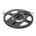
LED RGB Strip - Bare (5m)
COM-12022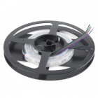
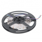
LED RGB Strip - Sealed (1m)
COM-12023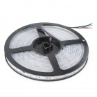
LED RGB Strip - Sealed (5m)
COM-12024Required Materials
To follow along with this tutorial, you will need the following materials. The partial wishlist on the left is for a basic connection with an Arduino. It does not include the potentiometer and buttons. The full wishlist on the right is for the full circuit for additional functionality. You may not need everything though depending on what you have. Add it to your cart, read through the guide, and adjust the cart as necessary.
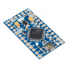
Microcontroller
To make the most out of your LED strip, you will need a microcontroller. The easiest would be to use the RedBoard Qwiic but you can use any Arduino microcontroller as long as it has a minimum of three PWM pins.


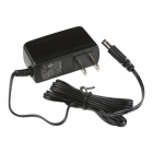
Power Supply
To power your LEDs, you will need a 12V power supply. The amount of current needed depends on the length and density of the LED strip. Below are a few options if you are powering the LEDs from a wall outlet in an installation. You could also use a 9V power supply. It may not be as bright but your LED strip will not be as hot.
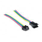
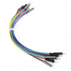
Wires and Connectors
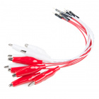
The stranded wires from the non-addressable do not have a connector. For prototyping you could use alligator clips with male headers. However, it would be easier to use a polarized connector like the ones from the 4-wire pigtail connector to easily connect and disconnect from your controller.

Transistors
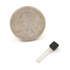
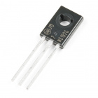
If you are using a microcontroller to control the strip, you will need transistors to control each channel. For small lengths, you could use NPN transistors. For longer lengths, you could use n-channel mosfets. Just make sure to get the associated resistors depending on your transistor.
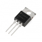
N-Channel MOSFET 60V 30A
COM-10213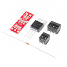
SparkFun MOSFET Power Control Kit
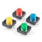
COM-12959Input
For options to adjust the color and brightness of your LED strip, you could use the following with a microcontroller.

Tools
You will need a soldering iron, solder, and general soldering accessories. You may also need some wire strippers if you are cutting and reusing parts of the strip.


Wire Strippers - 22-30AWG
TOL-14762Suggested Reading
If you aren’t familiar with the following concepts, we recommend checking out these tutorials before continuing. If you are looking to customize the control by programming a microcontroller, we recommend looking at the SparkFun Inventor's Kit for Arduino.
Pulse Width Modulation
Light-Emitting Diodes (LEDs)
LED Light Bar Hookup
Transistors
SparkFun Inventor's Kit Experiment Guide - v4.1
Hardware Overview
The non-addressable RGB LED strips are also referred to as analog LED strips. Each channel has three LEDs wired in series with a current limiting resistor. Each segment contains three common anode RGB LED ICs that are connected in parallel. These are used more on strips. While these operate at 12V, they can also light up with 9V.

Hardware Hookup
We'll be using a common anode RGB LED strip. There are a few methods of lighting the LED strip:
- straight power
- 555 Timer
- pre-programmed controller box
- microcontroller/single board computer
Below are three of these methods. For the scope of this tutorial, we will be using the third circuit diagram.
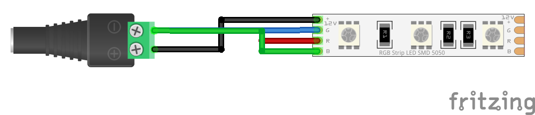
Hookup 1: Straight Power!
The simplest method of using non-addressable LEDs to illuminate your project is to add power to your LED strip. You will just need to make a connection between the female barrel jack adapter and the non-addressable LED strip. Simply insert the black wire connecting the "12V" pin to the "+" of the barrel jack adapter's screw terminal for power. Then insert the wire or your choice into the "-" screw terminal. In the following hookup, all channels were connected to ground to mix the color of white.
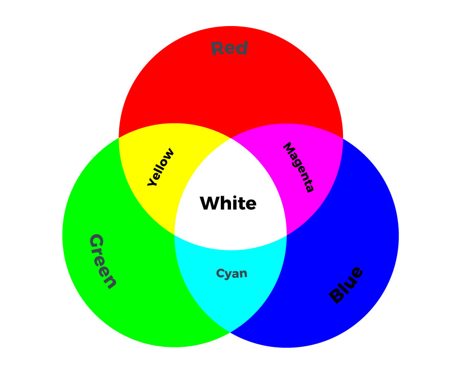
Depending on your project and color that you are illuminating, you will need to ground each respective channel. Here are some basic colors that you could mix by grounding different pins. The tradeoff is that you are limited to seven colors and will need to adjust the connection every time you need to change the color. For projects that do not require that many colors, this would be the best setup.
Hookup 2: Preprogrammed Controller Box
For those that are interested in a preprogrammed controller to easily control the non-addressable LED strip with a controller, you could use the Mi-Light remote and controller box. You will simply need to connect power through the barrel jack and tighten the screws for each channel. The controller box includes an additional "white" channel for LED strips with that have an the color.
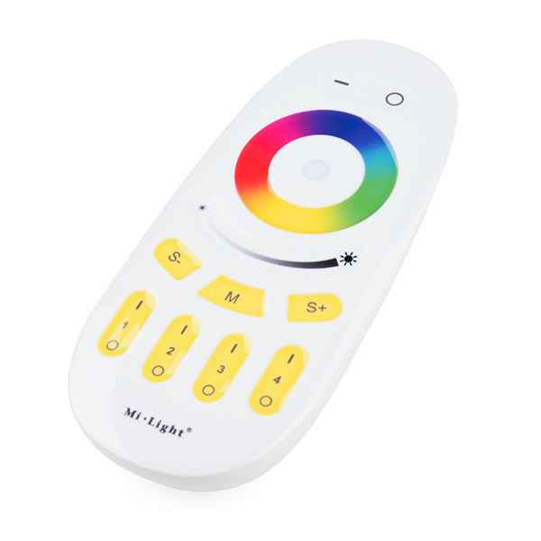
Mi-Light 4-Zone LED Remote Controller
COM-14711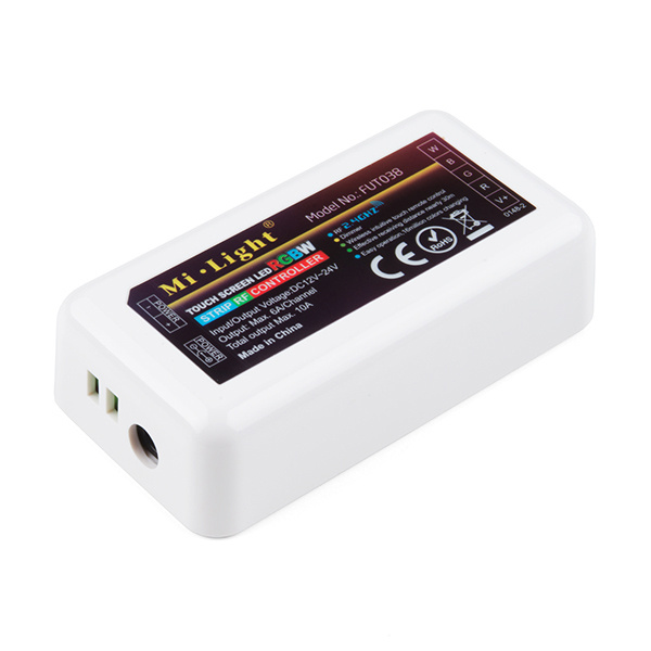
Mi-Light RGBW LED Controller Box
COM-14710For more information, check out the video below!
Hookup 3: Microcontroller
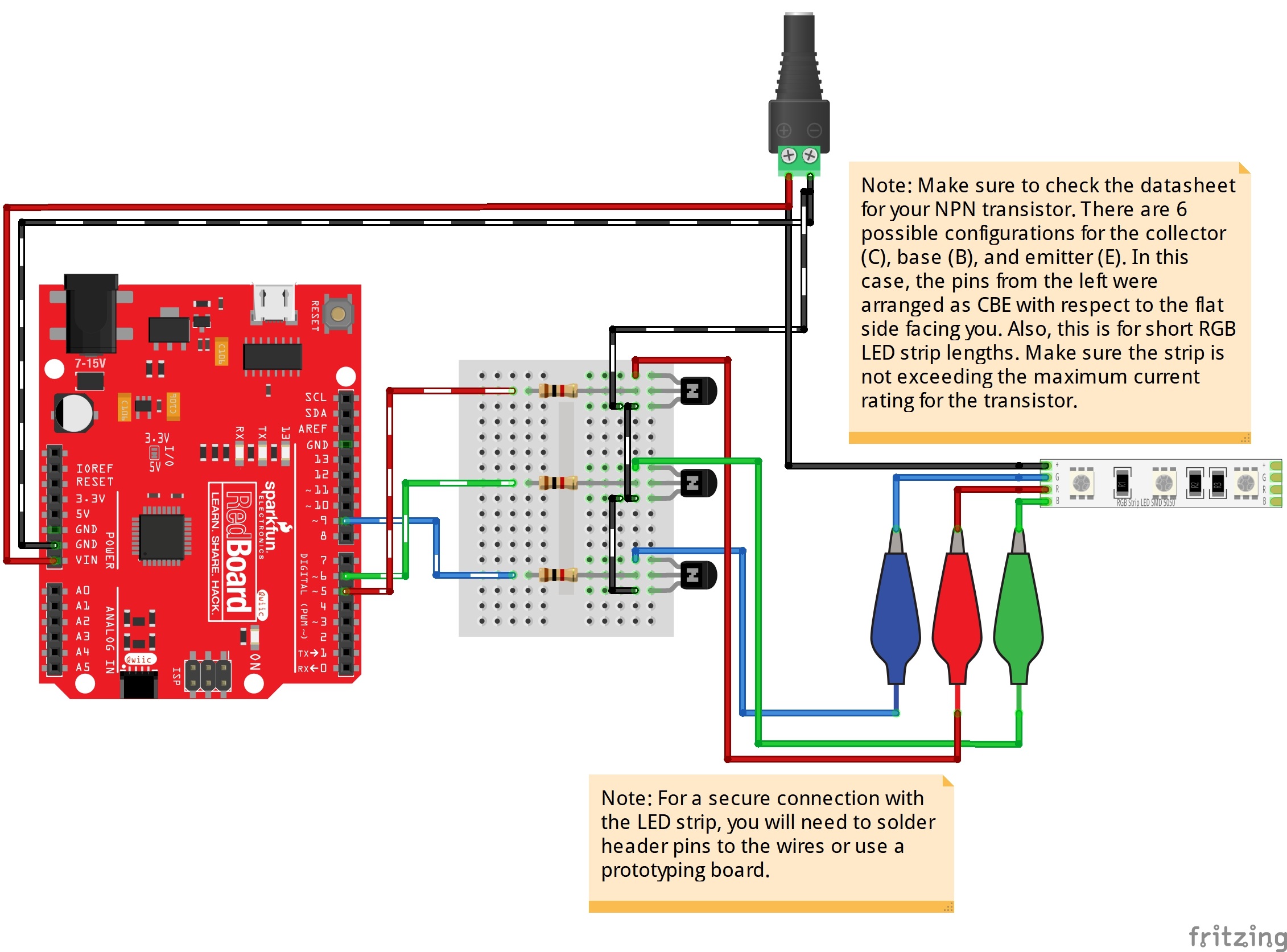
For those that want a little bit more flexibility and control over the LEDs, you can use a microcontroller. We'll be using a RedBoard Qwiic with the ATmega328P. You can use different microcontollers (i.e. AVR, ARM, micro:bit, ESP8266, ESP32, etc.) or single board computer (i.e. Raspberry Pi) as long as it can output a PWM signal. You just need a transistor since the logic level is lower than the voltage of the LED strip and the pins are not able to source enough current. The code (i.e. MakeCode, Python, etc.) depends on the microcontroller or single board computer. For the scope of the tutorial, we will be using the Arduino language to control the LEDs.
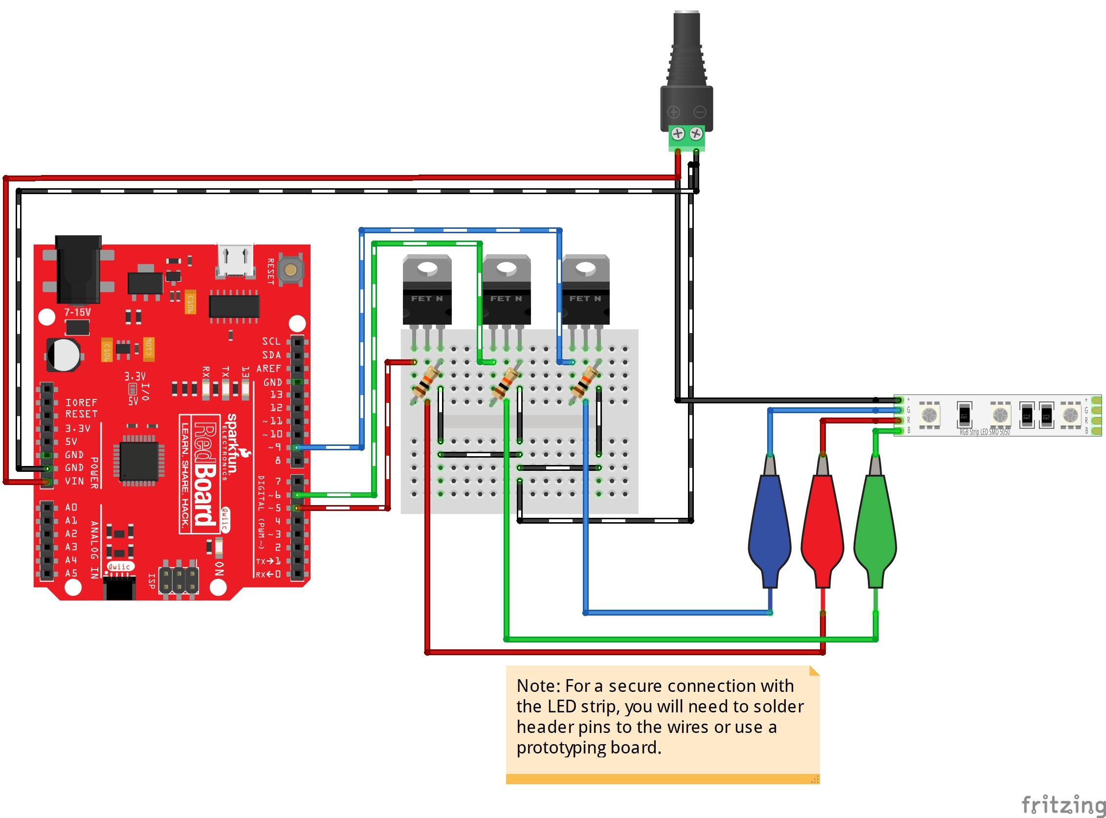
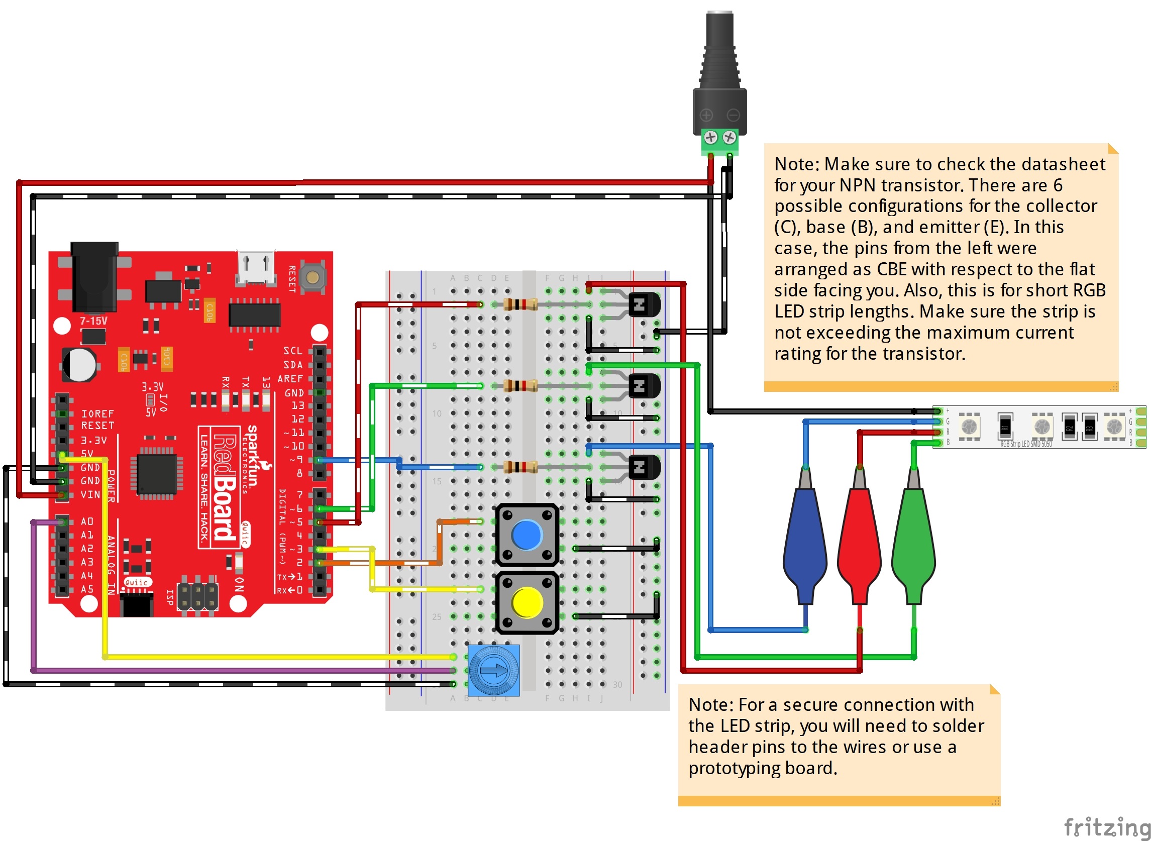
Typically for common anode RGB LED strips, you could use NPN BJTs or N-channel MOSFETs as a switch. N-channel mosfets usually can handle more power and they are more power efficient. Therefore, we'll be adding the load on the high side. Each color channel requires a transistor to switch. The hookup diagram for a basic connection is shown on the left. For additional functionality, you could add buttons and a potentiometer to control the LEDs. For testing purposes, we'll use a breadboard, jumper wires, and alligator clips to connect. You'll eventually want to solder the LED strip to header pins, a prototyping board, or splice a 4-pin pigtail connector for a secure connection when using it in an installation.
 |
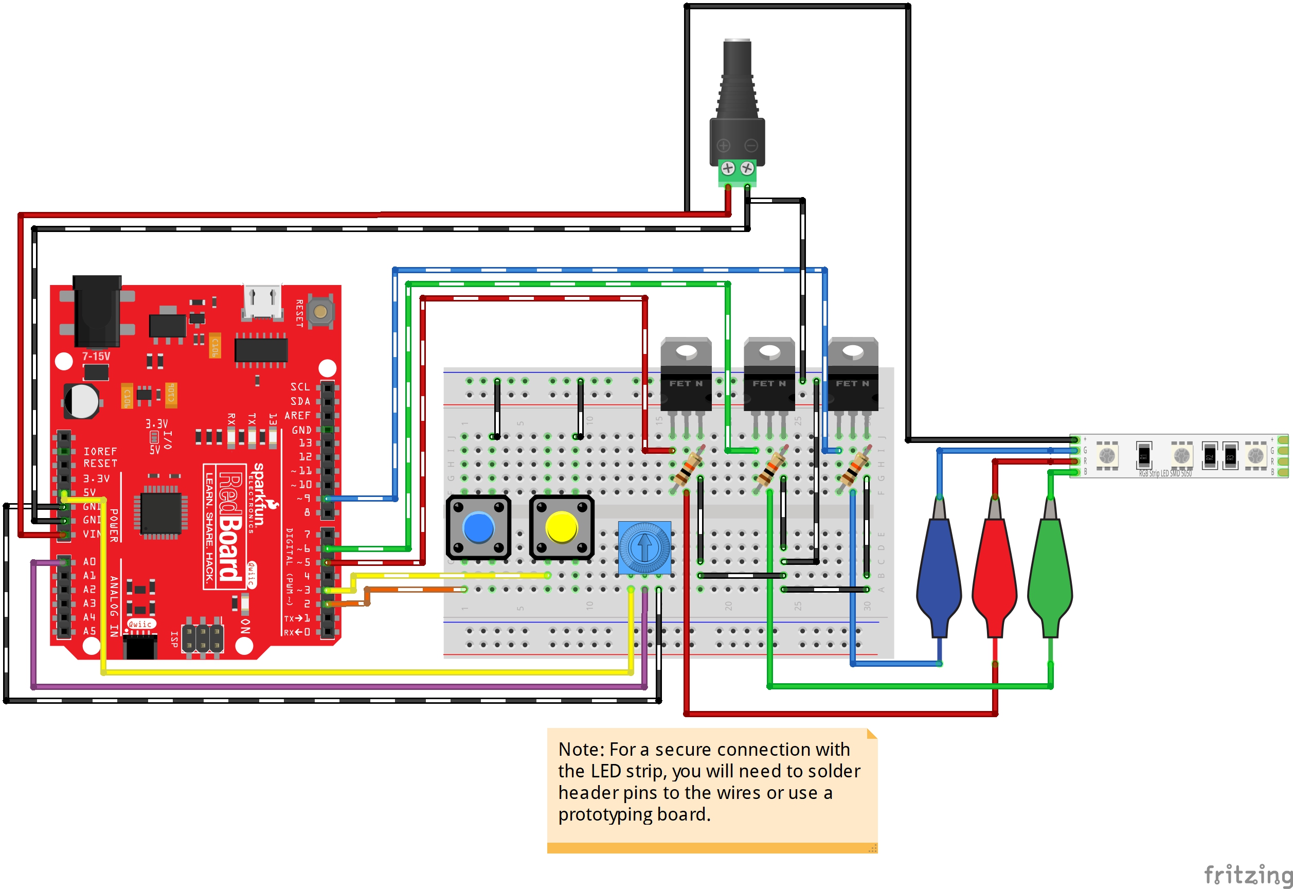 |
| Basic Arduino Hookup w/ N Channel MOSFETS | Buttons and Potentiometers Added for Additional Functionality |
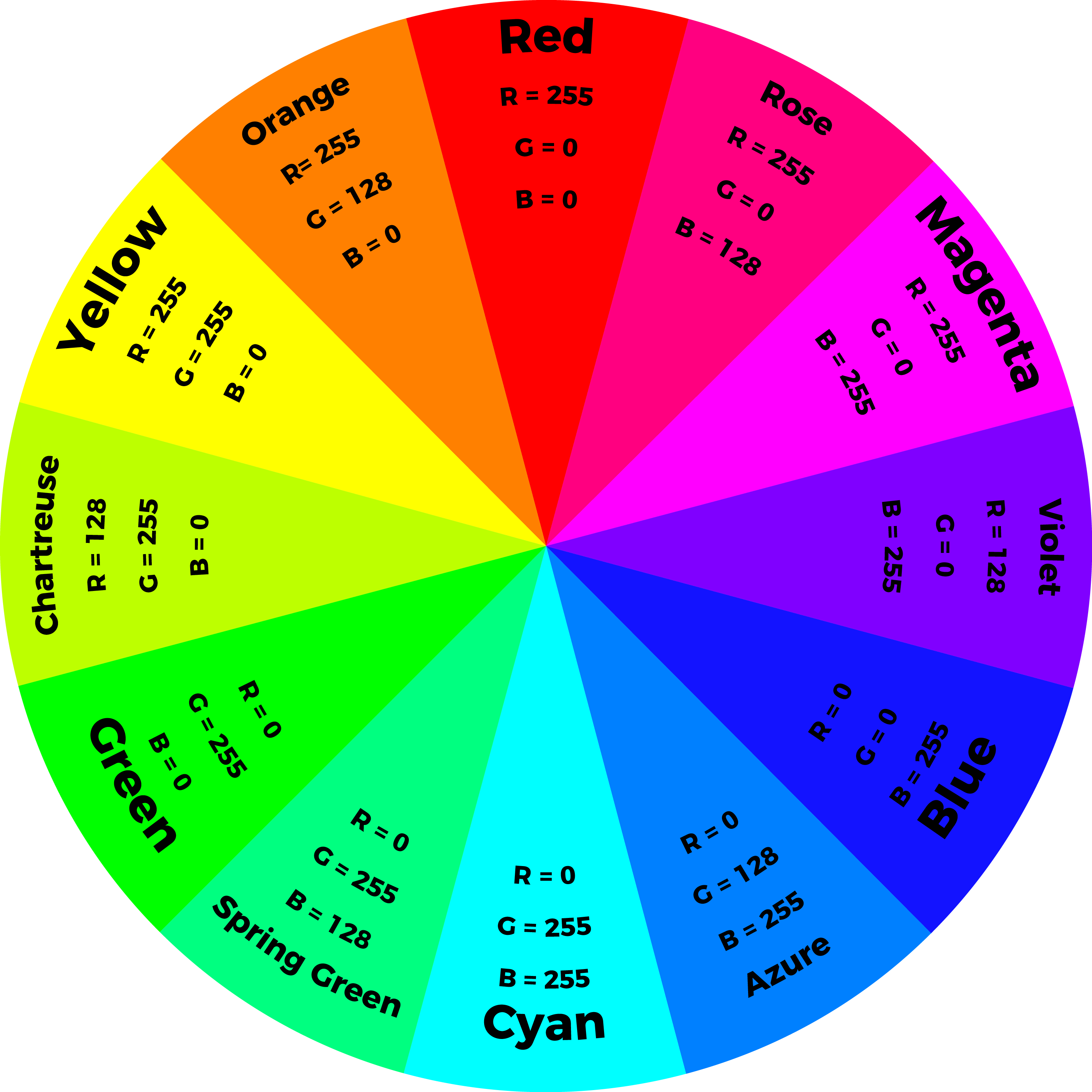
By using a PWM output from a microcontroller and transistor to adjust the brightness of each color channel individually, the RGB LED can display almost any color you choose! For simplicity, we'll limit the colors to twelve colors and white on an Arduino. The following values in the diagram will create the primary, secondary, and tertiary colors.
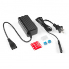
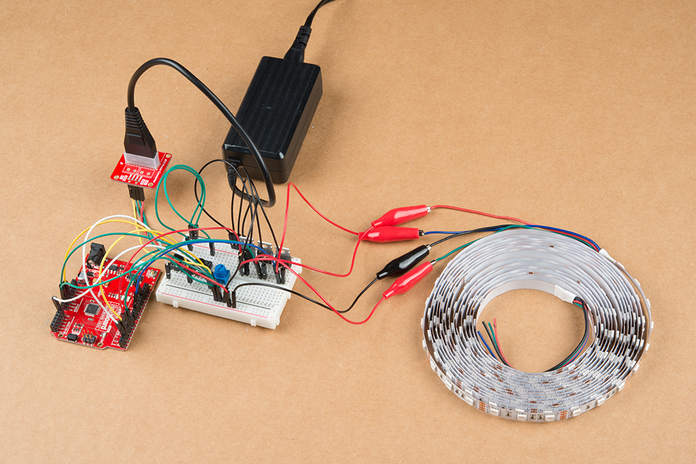
When using long strands, it is recommended to have a separate power supply for the Arduino and LEDs. Your setup should look similar to the image below on a breadboard if you are using a 12V/5V, 2A power supply and a 5M LED strip. The setup is the same except VIN is disconnected on the 12V. The Arduino is using its own 5V power. When programming the Arduino, it is recommended to disconnect the 5V pin so that you do not have conflicting power sources.
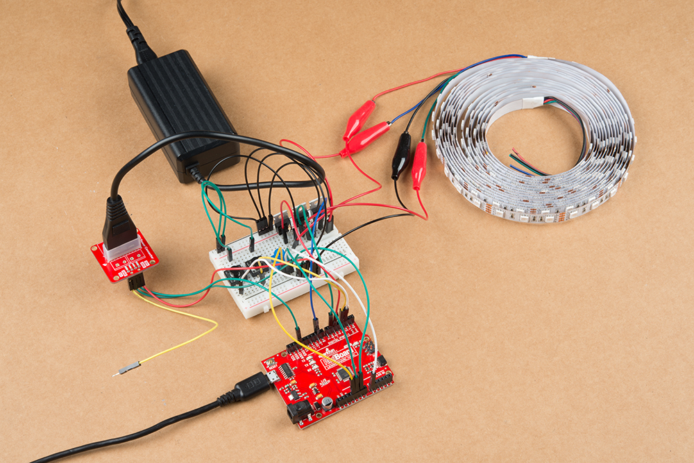
After you are done programming, you can remove the USB cable and connect the 12V/5V power supply's 5V pin to the circuit.
Arduino Example Code
Note: This example assumes you are using the latest version of the Arduino IDE on your desktop. If this is your first time using Arduino, please review our tutorial on installing the Arduino IDE.
To follow along, check out the GitHub repository. There are five examples in the repo. Two of which are simple examples to turn on a certain color based on the type of LED that you are using. We'll go over the other three examples.
The three examples from this GitHub Repo that we will go over are listed below. Click on one of the links below to jump to the example!
 |
 |
 |
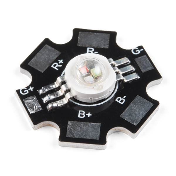 |
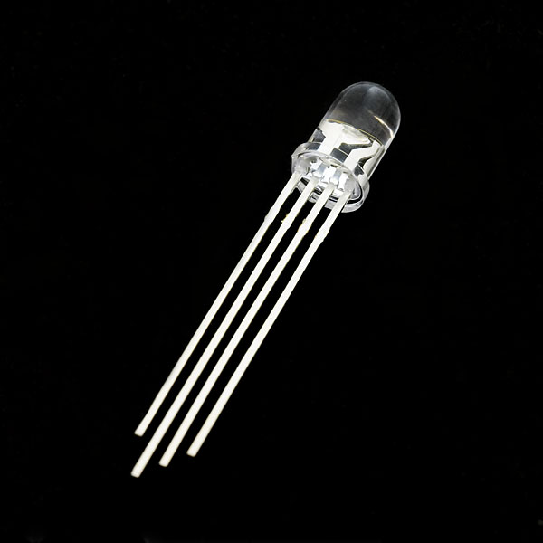
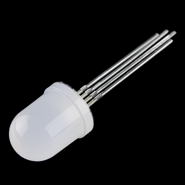
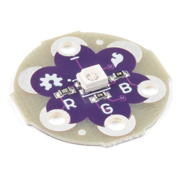
| Clear Common Anode RGB LED- 5mm | Diffused Common Cathode RGB LED- 10mm | SMD Common Cathode RGB LED on a Sewable PCB | High Power RGB LED on a PCB |
Example 1: Custom Color Cycling
This code will cycle through 12 colors and white. This is useful to test to see if you wired the colors correctly or want to show a color. There are options to adjust the brightness, type of LED, and rate at which the colors cycle.
If you have not already, unzip the GitHub repo and open the example code called Example1_RGB-CycleLED.ino. The path of the example code will probably look similar to: ... \ Non-Addresssable_RGB_LED_Strip_Code \ Firmware \ Arduino \ Example1_RGB-CycleLED. You can also copy the code below and paste it into the Arduino IDE. Select the board (in this case the Arduino/Genuino Uno) and COM port that the board enumerated to. Then hit the upload button to upload to your Arduino.
language:c
/******************************************************************************
  Example1_RGB-CycleLED.ino

  Non-Addressable RGB LED Custom Color Cycle
  WRITTEN BY: Ho Yun "Bobby" Chan @ SparkFun Electronics
  DATE: November 4, 2019
  GITHUB REPO: https://github.com/sparkfun/Non-Addresssable_RGB_LED_Strip_Code
  DEVELOPMENT ENVIRONMENT SPECIFICS:
    Firmware developed using Arduino IDE v1.8.9

  ============================== DESCRIPTION ==============================
  Expand your color options using analogWrite() and a non-addressable RGB LED.
  This code will cycle through 12 colors and white. There are options to adjust
  the brightness, type of LED, and rate at which the colors cycle.

  This example code works with an individual common anode and common cathode
  RGB LED. If you have a transistor or constant current LED driver, you can
  also use it to control an RGB LED strip or a higher power RGB LED.
  We'll assume that you are using a common anode LEDs in the strip. For more
  information checkout our tutorial: https://learn.sparkfun.com/tutorials/731

  Notes: There are twelve rainbow colors (primary, secondary, tertiary).
  Unlike digitalWrite(), which can be only HIGH (on) or LOW (off),
  analogWrite() lets you smoothly change the brightness from 0 (off) to 255 (fully on).
  When analogWrite() is used with the RGB LED, you can create millions of colors!
  For simplicity, we'll use 12 rainbow colors and white.  We will be blinking
  between each color.

  In the analogWrite() functions:
    0 is off
    128 is halfway on (used for the tertiary colors)
    255 is full brightness.

  ========== TUTORIAL ==========
  Non-Addressable RGB LED Strip Hookup Guide
  https://learn.sparkfun.com/tutorials/731

  Transistors | Applictions I: Switches
  https://learn.sparkfun.com/tutorials/transistors/all#applications-i-switches

  ==================== PRODUCTS THAT USE THIS CODE ====================
    LED RGB Strip (1M Bare) - https://www.sparkfun.com/products/12021
    LED RGB Strip (1M Sealed) - https://www.sparkfun.com/products/12023
    LED RGB Strip (5B Bare) - https://www.sparkfun.com/products/12022
    LED RGB Strip (5M Sealed) - https://www.sparkfun.com/products/12024
    Triple Output High Power RGB LED - https://www.sparkfun.com/products/15200

    PicoBuck LED Driver - https://www.sparkfun.com/products/13705
    N-Channel MOSFET Power Control Kit - https://www.sparkfun.com/products/12959

  ==================== HARDWARE CONNECTIONS ====================
  The hardware connection depends on your hardware and setup. Below is one possible
  arrangement.

  RGB Common Anode LED Strip => BJT/MOSFET => Arduino PWM Pin
      R pin => transistor => 5
      G pin => transistor => 6
      B pin => transistor => 9
      - pin                  -

  LICENSE: This code is released under the MIT License (http://opensource.org/licenses/MIT)

  ******************************************************************************/

//Debug mode, comment one of these lines out using a syntax
//for a single line comment ("//"):
//#define DEBUG 0     //0 = LEDs only
#define DEBUG 1     //1 = LEDs w/ serial output

// Define our LED pins to a PWM Pin
#define redPin 5
#define greenPin 6
#define bluePin 9

// Create integer variables for our LED color value
int redValue = 0;
int greenValue = 0;
int blueValue = 0;

//Create brightness variable
//Ranging from 0.0-1.0:
//  0.0 is off
//  0.5 is 50%
//  1.0 is fully on
float brightnessLED = 0.1;

//Create variables for type of LED and if it is used with a transistor
boolean commonAnode = false;
boolean commonCathode = true; //i.e.) When pin is HIGH, LED will also go HIGH without a transistor/PicoBuck

// Note:
//  Common Anode is `commonAnode`
//  Common Cathode LED is `commonCathode`
//  Common Anode RGB LED Strip with transistor is `!commonAnode`
//  RGB High Power LED with PicoBuck is also  `!commonAnode`
boolean rgbType = !commonAnode;

int blinkRate = 1000; //in milliseconds


void setup() {

  // Make all of our LED pins outputs:
  pinMode(redPin, OUTPUT);
  pinMode(greenPin, OUTPUT);
  pinMode(bluePin, OUTPUT);

  allOFF(); //initialize LEDs with it turned off
  rgbCalc();//calculate for RGB type
  rgbShow(); //make sure to show it happening

#if DEBUG
  Serial.begin(9600); //initialize Serial Monitor
  //while (!Serial); // Comment out to wait for serial port to connect to Serial Monitor. Option for native USB.
  Serial.println("Custom Color Cycling w/ an RGB LED. This example will cycle through 13 colors.");
  Serial.println(" ");
  Serial.println("Note: Make sure to adjust the code for a common cathode or common anode.");
  Serial.println(" ");
#endif

}//end setup()


void loop()
{
  //used to visually check when Arduino is initialized
#if DEBUG
  Serial.print("RED");
  Serial.print(" | Brightness % = ");
  Serial.println(brightnessLED * 100);
#endif
  redON();
  rgbCalc();
  rgbShow();
  delay(blinkRate);

#if DEBUG
  Serial.print("ORANGE");
  Serial.print(" | Brightness % = ");
  Serial.println(brightnessLED * 100);
#endif
  orangeON();
  rgbCalc();
  rgbShow();
  delay(blinkRate);

#if DEBUG
  Serial.print("YELLOW");
  Serial.print(" | Brightness % = ");
  Serial.println(brightnessLED * 100);
#endif
  yellowON();
  rgbCalc();
  rgbShow();
  delay(blinkRate);

#if DEBUG
  Serial.print("CHARTRUESE");
  Serial.print(" | Brightness % = ");
  Serial.println(brightnessLED * 100);
#endif
  chartrueseON();
  rgbCalc();
  rgbShow();
  delay(blinkRate);

#if DEBUG
  Serial.print("GREEN");
  Serial.print(" | Brightness % = ");
  Serial.println(brightnessLED * 100);
#endif
  greenON();
  rgbCalc();
  rgbShow();
  delay(blinkRate);

#if DEBUG
  Serial.print("SPRING GREEN");
  Serial.print(" | Brightness % = ");
  Serial.println(brightnessLED * 100);
#endif
  springGreenON();
  rgbCalc();
  rgbShow();
  delay(blinkRate);

#if DEBUG
  Serial.print("CYAN");
  Serial.print(" | Brightness % = ");
  Serial.println(brightnessLED * 100);
#endif
  cyanON();
  rgbCalc();
  rgbShow();
  delay(blinkRate);

#if DEBUG
  Serial.print("AZURE");
  Serial.print(" | Brightness % = ");
  Serial.println(brightnessLED * 100);
#endif
  azureON();
  rgbCalc();
  rgbShow();
  delay(blinkRate);

#if DEBUG
  Serial.print("BLUE");
  Serial.print(" | Brightness % = ");
  Serial.println(brightnessLED * 100);
#endif
  blueON();
  rgbCalc();
  rgbShow();
  delay(blinkRate);

#if DEBUG
  Serial.print("VIOLET");
  Serial.print(" | Brightness % = ");
  Serial.println(brightnessLED * 100);
#endif
  violetON();
  rgbCalc();
  rgbShow();
  delay(blinkRate);

#if DEBUG
  Serial.print("MAGENTA");
  Serial.print(" | Brightness % = ");
  Serial.println(brightnessLED * 100);
#endif
  magentaON();
  rgbCalc();
  rgbShow();
  delay(blinkRate);

#if DEBUG
  Serial.print("ROSE");
  Serial.print(" | Brightness % = ");
  Serial.println(brightnessLED * 100);
#endif
  roseON();
  rgbCalc();
  rgbShow();
  delay(blinkRate);

#if DEBUG
  Serial.print("WHITE");
  Serial.print(" | Brightness % = ");
  Serial.println(brightnessLED * 100);
#endif
  whiteON();
  rgbCalc();
  rgbShow();
  delay(blinkRate);

#if DEBUG
  Serial.print("OFF");
  Serial.print(" | Brightness % = ");
  Serial.println(brightnessLED * 100);
#endif
  allOFF();
  rgbCalc();
  rgbShow();
  delay(blinkRate);

}//end loop


// ==================== CUSTOM FUNCTIONS DEFINED BELOW ====================
void allOFF() {
  // Black (all LEDs off)
  // RGB LEDs:
  redValue = 0;
  greenValue =  0;
  blueValue = 0;
}

void redON() {
  // Red
  redValue = 255;
  greenValue =  0;
  blueValue = 0;
}

void orangeON() {
  // Orange
  redValue = 255;
  greenValue = 128;
  blueValue = 0;
}

void yellowON() {
  // Yellow
  redValue = 255;
  greenValue = 255;
  blueValue = 0;
}

void chartrueseON() {
  // Chartruese
  redValue = 128;
  greenValue = 255;
  blueValue = 0;
}

void greenON() {
  // Green
  redValue = 0;
  greenValue = 255;
  blueValue = 0;
}

void springGreenON() {
  // Spring Green
  redValue = 0;
  greenValue = 255;
  blueValue = 128;
}

void cyanON() {
  // Cyan
  redValue = 0;
  greenValue = 255;
  blueValue = 255;
}

void azureON() {
  // Azure
  redValue = 0;
  greenValue = 128;
  blueValue = 255;
}

void blueON() {
  // Blue
  redValue = 0;
  greenValue = 0;
  blueValue = 255;
}

void violetON() {
  // Violet
  redValue = 128;
  greenValue = 0;
  blueValue = 255;
}

void magentaON() {
  // Magenta
  redValue = 255;
  greenValue = 0;
  blueValue = 255;
}

void roseON() {
  // Rose
  redValue = 255;
  greenValue = 0;
  blueValue = 128;
}

void whiteON() {
  // White (all LEDs on)
  redValue = 255;
  greenValue = 255;
  blueValue = 255;
}


void rgbCalc() {
  //use this to correctly light up LED depending on the setup
  if (rgbType == commonAnode) {
    /* If using a common anode LED, a pin
       should turn ON the LED when the pin is LOW.*/
    redValue = 255 - redValue;
    greenValue = 255 - greenValue;
    blueValue = 255 - blueValue;

  }
  else {
    /* If using a common cathode LED, an analog pin
       should turn on the LED when the pin is HIGH. The
       logic is flipped when using a Common Anode RGB LED
       strip, NPN BJT/N-Channel MOSFET, and microcontroller

       Leave RGB values as is, we're good!*/
  }

  redValue = int(redValue * brightnessLED);
  greenValue = int(greenValue * brightnessLED);
  blueValue = int(blueValue * brightnessLED);
}

void rgbShow() {
  //once value is calculated, show the LED color
  analogWrite(redPin, redValue);
  analogWrite(greenPin, greenValue);
  analogWrite(bluePin, blueValue);
}
Once the code has been uploaded, the RGB LED will cycle through each of the 12 colors, white, and then turn off. Each color has its own function. When the function is called, the custom color will have a certain analog value for red, green, and blue. Before displaying the color, the values are calculated depending on the type of LED being used (either a common cathode or common anode). By default, we are assuming that the strip uses common anode LEDs but we are using a transistor to control them so rgbType is set to !commonAnode. The color is further calculated based on the intensity of the LED. After calculating the LED color lights up whenever the function rgbShow() is called.
Open the Arduino Serial Monitor set to 9600 baud to see the output as the color changes. Try adjusting the brightness or blink rate. If you are not seeing the correct color associated with the output, make sure to check your connections and ensure that the correct type of RGB LED is selected.

Example 2: Fading
This code will fade through 12 colors and white. There are options to adjust the brightness, type of LED, and rate at which the colors fade.
If you have not already, unzip the GitHub repo and open the example code called Example2_RGB-FadeLED.ino. The path of the example code will probably look similar to: ...Non-Addresssable_RGB_LED_Strip_Code\Firmware\Arduino\Example2_RGB-FadeLED.ino. You can also copy the code below and paste it into the Arduino IDE. Select the board (in this case the Arduino/Genuino Uno) and COM port that the board enumerated to. Then hit the upload button to upload to your Arduino.
language:c
/******************************************************************************
  Example2_RGB-FadeLED.ino

  Non-Addressable RGB LED Custom Color Fade
  WRITTEN BY: Ho Yun "Bobby" Chan @ SparkFun Electronics
  DATE: November 4, 2019
  GITHUB REPO: https://github.com/sparkfun/Non-Addresssable_RGB_LED_Strip_Code
  DEVELOPMENT ENVIRONMENT SPECIFICS:
    Firmware developed using Arduino IDE v1.8.9

  ============================== DESCRIPTION ==============================
  Expand your color options using analogWrite() and a non-addressable RGB LED.
  This code will fade through 12 colors and white. There are options to adjust
  the brightness, type of LED, and rate at which the colors fade.

  This example code works with an individual common anode and common cathode
  RGB LED. If you have a transistor or constant current LED driver, you can
  also use it to control an RGB LED strip or a higher power RGB LED.
  We'll assume that you are using a common anode LEDs in the strip. For more
  information checkout our tutorial: https://learn.sparkfun.com/tutorials/731

  Notes: There are twelve rainbow colors (primary, secondary, tertiary).
  Unlike digitalWrite(), which can be only HIGH (on) or LOW (off),
  analogWrite() lets you smoothly change the brightness from 0 (off) to 255 (fully on).
  When analogWrite() is used with the RGB LED, you can create millions of colors!
  For simplicity, we'll use 12 rainbow colors and white.  We will be fading
  between each color.

  In the analogWrite() functions:
    0 is off
    128 is halfway on (used for the tertiary colors)
    255 is full brightness.

  ========== TUTORIAL ==========
  Non-Addressable RGB LED Strip Hookup Guide
  https://learn.sparkfun.com/tutorials/731

  Transistors | Applictions I: Switches
  https://learn.sparkfun.com/tutorials/transistors/all#applications-i-switches

  ==================== PRODUCTS THAT USE THIS CODE ====================
    LED RGB Strip (1M Bare) - https://www.sparkfun.com/products/12021
    LED RGB Strip (1M Sealed) - https://www.sparkfun.com/products/12023
    LED RGB Strip (5B Bare) - https://www.sparkfun.com/products/12022
    LED RGB Strip (5M Sealed) - https://www.sparkfun.com/products/12024
    Triple Output High Power RGB LED - https://www.sparkfun.com/products/15200

    PicoBuck LED Driver - https://www.sparkfun.com/products/13705
    N-Channel MOSFET Power Control Kit - https://www.sparkfun.com/products/12959

  ==================== HARDWARE CONNECTIONS ====================
  The hardware connection depends on your hardware and setup. Below is one possible
  arrangement.

  RGB Common Anode LED Strip => BJT/MOSFET => Arduino PWM Pin
      R pin => transistor => 5
      G pin => transistor => 6
      B pin => transistor => 9
      - pin                  -

  LICENSE: This code is released under the MIT License (http://opensource.org/licenses/MIT)

  ******************************************************************************/

//Debug mode, comment one of these lines out using a syntax
//for a single line comment ("//"):
//#define DEBUG 0     //0 = LEDs only
#define DEBUG 1     //1 = LEDs w/ serial output

// Define our LED pins to a PWM Pin
#define redPin 5
#define greenPin 6
#define bluePin 9

// Create integer variables for our LED color value
int redValue = 0;
int greenValue = 0;
int blueValue = 0;

//Create brightness variable
//Ranging from 0.0-1.0:
//  0.0 is off
//  0.5 is 50%
//  1.0 is fully on
float brightnessLED = 0.1;

//Create variables for type of LED and if it is used with a transistor
boolean commonAnode = false;
boolean commonCathode = true;//i.e.) When pin is HIGH, LED will also go HIGH without a transistor/PicoBuck

// Note:
//  Common Anode is `commonAnode`
//  Common Cathode LED is `commonCathode`
//  Common Anode RGB LED Strip with transistor is `!commonAnode`
//  RGB High Power LED with PicoBuck is also  `!commonAnode`
boolean rgbType = !commonAnode;

int colorMode = 1; //color mode to control LED color

//Variables for fading LED
int prevFadeVal = 0;
int currentFadeVal = 0;
boolean increasing = true;
int fadeVal = 5; //value to step when increasing/decreasing, recommended to be 1 or 5, larger numbers will have problems lighting up
int fadeMAX = 255; //maximum fade value
int fadeMIN = 0;   //minimum fade value
int fadeDelay = 30;//delay between each step


void setup() {

  // Make all of our LED pins outputs
  pinMode(redPin, OUTPUT);
  pinMode(greenPin, OUTPUT);
  pinMode(bluePin, OUTPUT);

  allOFF(); //make sure to initialize LEDs with it turned off
  rgbCalc();//calculate for RGB type
  rgbShow(); //make sure to show it happening

#if DEBUG
  Serial.begin(9600); //initialize Serial Monitor
  //while (!Serial); // Comment out to wait for serial port to connect to Serial Monitor. Option for native USB.
  Serial.println("Custom Color Fading w/ an RGB LED.");
  Serial.println(" ");
  Serial.println("Note: Make sure to adjust the code for a common cathode or common anode.");
  Serial.println(" ");
#endif

}//end setup()

void loop()
{


  switch (colorMode) {
    case 1://FADE RED
      redValue = currentFadeVal;
      greenValue = 0;
      blueValue = 0;

      rgbCalc();
      break;
    //========== END FADE RED ==========

    case 2://FADE ORANGE
      redValue = currentFadeVal;
      greenValue = currentFadeVal * 0.498; // 128/255 = ~0.498039
      blueValue = 0;

      rgbCalc();

      if (redValue > 0 && greenValue == 0) {
        //tertiary component is 1/2, so when it calculates to decimal with fade value,
        //it will be basically be off, make sure to turn off other color so that
        //it does not just show the other color
        redValue = 0;
      }

      // takes x amount of steps if you do not set it to zero for certain brightness (i.e. takes 8 more steps to turn off for 0.1)
      //Serial.print("Red Value =");
      //Serial.println( int((currentFadeVal) * brightnessLED));

      //Serial.print("Green Value =");
      //Serial.println( int((currentFadeVal * 0.498) * brightnessLED));
      break;
    //========== END FADE ORANGE ==========

    case 3://FADE YELLOW
      redValue = currentFadeVal;
      greenValue = currentFadeVal;
      blueValue = 0;

      rgbCalc();
      break;
    //========== END FADE YELLOW ==========

    case 4://FADE CHARTRUESE
      redValue = currentFadeVal * 0.498; // 128/255 = ~0.498039
      greenValue = currentFadeVal;
      blueValue = 0;

      rgbCalc();

      if (greenValue > 0 && redValue == 0) {
        //tertiary component is 1/2, so when it calculates to decimal with fade value,
        //it will be basically be off, make sure to turn off other color so that
        //it does not just show the other color
        greenValue = 0;
      }
      break;
    //========== END FADE CHARTRUESE ==========

    case 5://FADE GREEN
      redValue = 0;
      greenValue = currentFadeVal;
      blueValue = 0;

      rgbCalc();
      break;
    //========== END FADE GREEN ==========

    case 6://FADE SPRING GREEN
      redValue = 0;
      greenValue = currentFadeVal;
      blueValue = currentFadeVal * 0.498; // 128/255 = ~0.498039

      rgbCalc();

      if (greenValue > 0 && blueValue == 0) {
        //tertiary component is 1/2, so when it calculates to decimal with fade value,
        //it will be basically be off, make sure to turn off other color so that
        //it does not just show the other color
        greenValue = 0;
      }
      break;
    //========== END FADE SPRING GREEN ==========

    case 7://FADE CYAN
      redValue = 0;
      greenValue = currentFadeVal;
      blueValue = currentFadeVal;

      rgbCalc();
      break;
    //========== END FADE CYAN ==========

    case 8://FADE AZURE
      redValue = 0;
      greenValue = currentFadeVal * 0.498; // 128/255 = ~0.498039
      blueValue = currentFadeVal;

      rgbCalc();

      if (blueValue > 0 && greenValue == 0) {
        //tertiary component is 1/2, so when it calculates to decimal with fade value,
        //it will be basically be off, make sure to turn off other color so that
        //it does not just show the other color
        blueValue = 0;
      }
      break;
    //========== END FADE AZURE ==========

    case 9://FADE BLUE
      redValue = 0;
      greenValue = 0;
      blueValue = currentFadeVal;

      rgbCalc();
      break;
    //========== END FADE BLUE ==========

    case 10://FADE VIOLET
      redValue = currentFadeVal * 0.498;
      greenValue = 0;
      blueValue = currentFadeVal;

      rgbCalc();

      if (blueValue > 0 && redValue == 0) {
        //tertiary component is 1/2, so when it calculates to decimal with fade value,
        //it will be basically be off, make sure to turn off other color so that
        //it does not just show the other color
        blueValue = 0;
      }
      break;
    //========== END FADE VIOLET ==========

    case 11://FADE MAGENTA
      redValue = currentFadeVal;
      greenValue = 0;
      blueValue = currentFadeVal;

      rgbCalc();
      break;
    //========== END FADE MAGENTA ==========

    case 12://FADE ROSE
      redValue = currentFadeVal;
      greenValue = 0;
      blueValue = currentFadeVal * 0.498;

      rgbCalc();

      if (redValue > 0 && blueValue == 0) {
        //tertiary component is 1/2, so when it calculates to decimal with fade value,
        //it will be basically be off, make sure to turn off other color so that
        //it does not just show the other color
        redValue = 0;
      }
      break;
    //========== END FADE ROSE ==========

    case 13://FADE WHITE
      redValue = currentFadeVal;
      greenValue = currentFadeVal;
      blueValue = currentFadeVal;

      rgbCalc();
      break;
    //========== END FADE WHITE ==========

    default:
      allOFF();
      rgbCalc();
      break;
  }


#if DEBUG
  Serial.print("Color Fading = ");
  if (colorMode == 1) {
    Serial.print("RED");
  }
  else if (colorMode == 2) {
    Serial.print("ORANGE");
  }
  else if (colorMode == 3) {
    Serial.print("YELLOW");
  }
  else if (colorMode == 4) {
    Serial.print("CHARTRUESE");
  }
  else if (colorMode == 5) {
    Serial.print("GREEN");
  }
  else if (colorMode == 6) {
    Serial.print("SPRING GREEN");
  }
  else if (colorMode == 7) {
    Serial.print("CYAN");
  }
  else if (colorMode == 8) {
    Serial.print("AZURE");
  }
  else if (colorMode == 9) {
    Serial.print("BLUE");
  }
  else if (colorMode == 10) {
    Serial.print("VIOLET");
  }
  else if (colorMode == 11) {
    Serial.print("MAGENTA");
  }
  else if (colorMode == 12) {
    Serial.print("ROSE");
  }
  else if (colorMode == 13) {
    Serial.print("WHITE");
  }
  else {
    Serial.print("OFF");
  }
  Serial.print(" | Brightness % = ");
  Serial.print(brightnessLED * 100);
  Serial.print("%");

  Serial.print(" | Fade Val Before Calc= ");
  Serial.println(currentFadeVal);
#endif

  rgbShow();
  delay(fadeDelay);


  if (increasing == true) {
    //increasing
    currentFadeVal += fadeVal;
  }
  else {
    //decreasing
    currentFadeVal -= fadeVal;
  }

  if (currentFadeVal > fadeMAX) {
    increasing = false;
    prevFadeVal -= fadeVal;//undo addition

    currentFadeVal = prevFadeVal;
  }
  else if (currentFadeVal < fadeMIN) {
    increasing = true;
    prevFadeVal += fadeVal;//undo subtraction

    currentFadeVal = prevFadeVal;

    colorMode += 1;//next color
    if (colorMode > 13) {
      colorMode = 0;
    }
  }

  prevFadeVal = currentFadeVal;

}//END LOOP


// ==================== CUSTOM FUNCTIONS DEFINED BELOW ====================
void allOFF() {
  // Black (all LEDs off)
  // RGB LEDs:
  redValue = 0;
  greenValue =  0;
  blueValue = 0;

  rgbCalc();
}

void redON() {
  // Red
  redValue = 255;
  greenValue =  0;
  blueValue = 0;

  rgbCalc();
}

void orangeON() {
  // Orange
  redValue = 255;
  greenValue = 128;
  blueValue = 0;

  rgbCalc();
}

void yellowON() {
  // Yellow
  redValue = 255;
  greenValue = 255;
  blueValue = 0;

  rgbCalc();
}

void chartrueseON() {
  // Chartruese
  redValue = 128;
  greenValue = 255;
  blueValue = 0;

  rgbCalc();
}

void greenON() {
  // Green
  redValue = 0;
  greenValue = 255;
  blueValue = 0;

  rgbCalc();
}

void springGreenON() {
  // Spring Green
  redValue = 0;
  greenValue = 255;
  blueValue = 128;

  rgbCalc();
}

void cyanON() {
  // Cyan
  redValue = 0;
  greenValue = 255;
  blueValue = 255;

  rgbCalc();
}

void azureON() {
  // Azure
  redValue = 0;
  greenValue = 128;
  blueValue = 255;

  rgbCalc();
}

void blueON() {
  // Blue
  redValue = 0;
  greenValue = 0;
  blueValue = 255;

  rgbCalc();
}

void violetON() {
  // Violet
  redValue = 128;
  greenValue = 0;
  blueValue = 255;

  rgbCalc();
}

void magentaON() {
  // Magenta
  redValue = 255;
  greenValue = 0;
  blueValue = 255;

  rgbCalc();
}

void roseON() {
  // Rose
  redValue = 255;
  greenValue = 0;
  blueValue = 128;

  rgbCalc();
}

void whiteON() {
  // White (all LEDs on)
  redValue = 255;
  greenValue = 255;
  blueValue = 255;

  rgbCalc();
}


void rgbCalc() {
  //use this to correctly light up LED depending on the setup
  if (rgbType == commonAnode) {
    /* If using a common anode LED, a pin
       should turn ON the LED when the pin is LOW.*/
    redValue = 255 - redValue;
    greenValue = 255 - greenValue;
    blueValue = 255 - blueValue;

  }
  else {
    /* If using a common cathode LED, an analog pin
       should turn on the LED when the pin is HIGH. The
       logic is flipped when using a Common Anode RGB LED
       strip, NPN BJT/N-Channel MOSFET, and microcontroller

       Leave RGB values as is, we're good!*/
  }

  redValue = int(redValue * brightnessLED);
  greenValue = int(greenValue * brightnessLED);
  blueValue = int(blueValue * brightnessLED);
}

void rgbShow() {
  //once value is calculated, show the LED color
  analogWrite(redPin, redValue);
  analogWrite(greenPin, greenValue);
  analogWrite(bluePin, blueValue);
}
Once the code has been uploaded, you should see the colors fading in and out. Open the serial monitor at 9600 to see what color is fading and its respective fade value. Due to the calculations and serial output, the fading can appear to be slow. You may want to adjust the baud rate to a higher value like 115200, adjust the fade delay, or turn off the debugging by defining DEBUG as 0. Additionally, the LEDs may turn off if the fade value and brightness is too small. This is due to the minimum voltage required to turn on the LEDs. You should see something similar to the GIF below. The GIF repeats a small sample of the colors fading. You will see all of the colors cycling in your setup.

Example 3: Full Demo
// in front of this line of code.
//brightnessLED = analogRead(knobPin) / 1023.0; //potentiometer for Brightnessloop().
This code will turn on a color, blink, fade, or cycle through 12 colors depending on the button input. The color cycle used in this demo will fade between each of the 12 colors. There are options to adjust the brightness, type of LED, and rate at which the colors cycle. The RedBoard will only change the color and pattern after pressing the button again.
If you have not already, unzip the GitHub repo and open the example code called Example3_RGB-FullDemoLED.ino. The path of the example code will probably look similar to: ...Non-Addresssable_RGB_LED_Strip_Code\Firmware\Arduino\Example3_RGB-FullDemoLED. You can also copy the code below and paste it into the Arduino IDE. Select the board (in this case the Arduino/Genuino Uno) and COM port that the board enumerated to. Then hit the upload button to upload to your Arduino.
language:c
/******************************************************************************
  Example3_RGB-FullDemoLED.ino

  Non-Addressable RGB LED Full Demo
  WRITTEN BY: Ho Yun "Bobby" Chan @ SparkFun Electronics
  DATE: November 4, 2019
  GITHUB REPO: https://github.com/sparkfun/Non-Addresssable_RGB_LED_Strip_Code
  DEVELOPMENT ENVIRONMENT SPECIFICS:
    Firmware developed using Arduino IDE v1.8.9

  ============================== DESCRIPTION ==============================
  Expand your color options using analogWrite() and a non-addressable RGB LED.
  This code will either turn on a color, blink, fade, or cycle through 12
  colors and white depending on the button input. There are options to adjust
  the brightness, type of LED, and rate at which the colors blink/fade/cycle.

  This example code works with an individual common anode and common cathode
  RGB LED. If you have a transistor or constant current LED driver, you can
  also use it to control an RGB LED strip or a higher power RGB LED.
  We'll assume that you are using a common anode LEDs in the strip. For more
  information checkout our tutorial: https://learn.sparkfun.com/tutorials/731

  Notes: There are twelve rainbow colors (primary, secondary, tertiary).
  Unlike digitalWrite(), which can be only HIGH (on) or LOW (off),
  analogWrite() lets you smoothly change the brightness from 0 (off) to 255 (fully on).
  When analogWrite() is used with the RGB LED, you can create millions of colors!
  For simplicity, we'll use 12 rainbow colors and white.

  In the analogWrite() functions:
    0 is off
    128 is halfway on (used for the tertiary colors)
    255 is full brightness.

  ========== TUTORIAL ==========
  Non-Addressable RGB LED Strip Hookup Guide
  https://learn.sparkfun.com/tutorials/731

  Transistors | Applictions I: Switches
  https://learn.sparkfun.com/tutorials/transistors/all#applications-i-switches

  ==================== PRODUCTS THAT USE THIS CODE ====================
    LED RGB Strip (1M Bare) - https://www.sparkfun.com/products/12021
    LED RGB Strip (1M Sealed) - https://www.sparkfun.com/products/12023
    LED RGB Strip (5B Bare) - https://www.sparkfun.com/products/12022
    LED RGB Strip (5M Sealed) - https://www.sparkfun.com/products/12024
    Triple Output High Power RGB LED - https://www.sparkfun.com/products/15200

    PicoBuck LED Driver - https://www.sparkfun.com/products/13705
    N-Channel MOSFET Power Control Kit - https://www.sparkfun.com/products/12959

  ==================== HARDWARE CONNECTIONS ====================
  The hardware connection depends on your hardware and setup. Below is one possible
  arrangement.

  RGB Common Anode LED Strip => BJT/MOSFET => Arduino PWM Pin
      R pin => transistor => 5
      G pin => transistor => 6
      B pin => transistor => 9
      - pin                  -

  LICENSE: This code is released under the MIT License (http://opensource.org/licenses/MIT)

  ******************************************************************************/

//Debug mode, comment one of these lines out using a syntax
//for a single line comment ("//"):
//#define DEBUG 0     //0 = LEDs only
#define DEBUG 1     //1 = LEDs w/ serial output

// Define our LED pins to a PWM Pin
#define redPin 5
#define greenPin 6
#define bluePin 9

// Create integer variables for our LED color value
int redValue = 0;
int greenValue = 0;
int blueValue = 0;

// Define our Potentiometer to a Analog Pin for Brightness
// This is needed if you use a Potentiometer
#define knobPin A0

//Create brightness variable
//Ranging from 0.0-1.0:
//  0.0 is off
//  0.5 is 50%
//  1.0 is fully on
float brightnessLED = 0.1;

//Create variables for type of LED and if it is used with a transistor
boolean commonAnode = false;
boolean commonCathode = true;//i.e.) When pin is HIGH, LED will also go HIGH without a transistor/PicoBuck

// Note:
//  Common Anode LED is `commonAnode`
//  Common Cathode LED is `commonCathode`
//  Common Anode RGB LED Strip with transistor is `!commonAnode`
//  RGB High Power LED with PicoBuck is also  `!commonAnode`
boolean rgbType = !commonAnode;

//Variables to keep track of color and pattern
int colorMode = 0; //color mode to control LED color
int pattern = 0; //pattern to turn off, stay on, fade, blink

//Variables for fading LED
int prevFadeVal = 0;
int currentFadeVal = 0;
boolean increasing = true;
int fadeVal = 5; //value to step when increasing/decreasing, recommended to be 1 or 5, larger numbers will have problems lighting up
int fadeMAX = 255; //maximum fade value
int fadeMIN = 0;   //minimum fade value
int fadeDelay = 30;//delay between each step

//Variables for blinking LED
int blinkVal = 0;
boolean blinkON = false;
int counter = 0; //use as a "delay"
int blinkRate = 750; //in milliseconds

//Variables to transition between RGB in a rainbow
int rainbowRedVal = 0;
int rainbowGreenVal = 0;
int rainbowBlueVal = 0;
int rainbowTransitionVal = 0;
int rainbowDelay = 5; //in milliseconds to transition between colors

//Note: You'll want to not make `rainbowDelay` too long as this will
//      cause delays with button presses

//Button variables for color
const int button1Pin = 2;
boolean button1State = false;
boolean prevbutton1State = false;
boolean currentbutton1State = false;

//Button variables for pattern
const int button2Pin = 3;
boolean button2State = false;
boolean prevbutton2State = false;
boolean currentbutton2State = false;


void setup() {

  // Make all of our LED pins outputs:
  pinMode(redPin, OUTPUT);
  pinMode(greenPin, OUTPUT);
  pinMode(bluePin, OUTPUT);

  if (rgbType == commonAnode) {
    //set values 255 to turn off OFF if common anode
    rainbowRedVal = 255;
    rainbowGreenVal = 255;
    rainbowBlueVal = 255;
  }

  sequenceTest();//visually initialization
  allOFF(); //make sure to initialize LEDs with it turned off
  rgbCalc();//calculate for RGB type
  rgbShow(); //make sure to show it happening

  pinMode(button1Pin, INPUT_PULLUP); //use internal pullup resistor with button
  pinMode(button2Pin, INPUT_PULLUP); //use internal pullup resistor with button

#if DEBUG
  Serial.begin(9600); //initialize Serial Monitor
  //while (!Serial); // Comment out to wait for serial port to connect to Serial Monitor. Option for native USB.
  Serial.println("Custom Color Mixing Demo w/ an RGB LED. Toggling the buttons will adjust the color and pattern.");
  Serial.println(" ");
  Serial.println("Note: Make sure to adjust the code for a common cathode or common anode.");
  Serial.println("Default is set to no color and off!");
  Serial.println(" ");
#endif

}//end setup()


void loop()
{
  button1State = digitalRead(button1Pin);// button for Color Mode
  button2State = digitalRead(button2Pin);// button for Pattern

  //==================== CHECK POTENTIOMETER FOR BRIGHTNESS ====================
  //Uncomment the line below if you are using a potentiometer or photoresistor (i.e. light sensor)
  //brightnessLED = analogRead(knobPin) / 1023.0; //potentiometer for Brightness

  /* Note: If you do not have a potentiometer or analog sensor attached,
    the LEDs will flicker when the LED pulls a certain amount of power
    due to the pin floating. Make sure to also GND the sensor close to your
    Arduino to reduce the noise.

    The LEDs can flicker at low values when using the fade mode. Make sure
    to adjust the potentiometer to a certain brightness or fade values
    for smooth fading.*/

  /*
    #if DEBUG
    Serial.print(" Brightness Value % = ");
    Serial.println(brightnessLED * 100);
    #endif
  */
  //==================== END CHECK POTENTIOMETER FOR BRIGHTNESS ====================

  //==================== CHECK BUTTON FOR COLOR MODE ====================
  //if button is pressed, it will be pulled low
  if (button1State == LOW) {
    currentbutton1State = true; // button has been pressed once

    if (prevbutton1State != currentbutton1State) { //check to see if button is still being pressed
      colorMode = colorMode + 1; //change color MODE after button has been pressed
#if DEBUG
      Serial.print("Color Mode = ");
      if (colorMode == 1) {
        Serial.println("RED");
      }
      else if (colorMode == 2) {
        Serial.println("ORANGE");
      }
      else if (colorMode == 3) {
        Serial.println("YELLOW");
      }
      else if (colorMode == 4) {
        Serial.println("CHARTRUESE");
      }
      else if (colorMode == 5) {
        Serial.println("GREEN");
      }
      else if (colorMode == 6) {
        Serial.println("SPRING GREEN");
      }
      else if (colorMode == 7) {
        Serial.println("CYAN");
      }
      else if (colorMode == 8) {
        Serial.println("AZURE");
      }
      else if (colorMode == 9) {
        Serial.println("BLUE");
      }
      else if (colorMode == 10) {
        Serial.println("VIOLET");
      }
      else if (colorMode == 11) {
        Serial.println("MAGENTA");
      }
      else if (colorMode == 12) {
        Serial.println("ROSE");
      }
      else if (colorMode == 13) {
        Serial.println("WHITE");
      }
      else {
        Serial.println("OFF");
      }
#endif

      //Cycle through colors when pressing buttons
      if (colorMode < 0 || colorMode > 13) {
        //reset ledMode
        colorMode = 0;
        allOFF();
        rgbCalc();
        rgbShow();
      }
    }
    else { //do nothing because finger is still on button
    }
    prevbutton1State = currentbutton1State;//update button1 state
  }


  //button has not been pressed, it will be high
  else {
    currentbutton1State = false;
    prevbutton1State = currentbutton1State;//update button1 state
  }

  //==================== END CHECK BUTTON FOR COLOR MODE ====================

  //==================== CHECK BUTTON FOR PATTERN ====================
  if (button2State == LOW) {
    currentbutton2State = true; //button has been pressed once

    if (prevbutton2State != currentbutton2State) { //check to see if button is still being pressed
      pattern = pattern + 1; //change LED pattern after button has been pressed

#if DEBUG
      Serial.print("Pattern = ");
      if (pattern == 1) {
        Serial.println("ON");//print what pattern
      }
      else if (pattern == 2) {
        Serial.println("FADE");//print what pattern
      }
      else if (pattern == 3) {
        Serial.println("BLINK");//print what pattern
      }
      else if (pattern == 4) {
        Serial.println("RAINBOW");//print what pattern
      }
      else {
        Serial.println("OFF");//print what pattern
      }
#endif


      if (pattern < 0 || pattern > 4) {
        //reset pattern
        pattern = 0;
      }
    }


    else { //do nothing because finger is still on button
    }
    prevbutton2State = currentbutton2State; //update button2 state
  }

  //button has not been pressed, it will be high
  else {
    currentbutton2State = false;
    prevbutton2State = currentbutton2State; //update button2 state
  }
  switch (pattern) {
    case 1:
      patternON();
      break;
    case 2:
      patternFade();
      break;
    case 3:
      patternBlink();
      break;
    case 4:
      patternRainbow();
      break;
    default:
      allOFF();
      rgbCalc();
      rgbShow();
      break;
  }
  //==================== END CHECK BUTTON FOR PATTERN ====================


}//end loop


// ==================== CUSTOM FUNCTIONS DEFINED BELOW ====================
void allOFF() {
  // Black (all LEDs off)
  // RGB LEDs:
  redValue = 0;
  greenValue =  0;
  blueValue = 0;
}

void redON() {
  // Red
  redValue = 255;
  greenValue =  0;
  blueValue = 0;
}

void orangeON() {
  // Orange
  redValue = 255;
  greenValue = 128;
  blueValue = 0;
}

void yellowON() {
  // Yellow
  redValue = 255;
  greenValue = 255;
  blueValue = 0;
}

void chartrueseON() {
  // Chartruese
  redValue = 128;
  greenValue = 255;
  blueValue = 0;
}

void greenON() {
  // Green
  redValue = 0;
  greenValue = 255;
  blueValue = 0;
}

void springGreenON() {
  // Spring Green
  redValue = 0;
  greenValue = 255;
  blueValue = 128;
}

void cyanON() {
  // Cyan
  redValue = 0;
  greenValue = 255;
  blueValue = 255;
}

void azureON() {
  // Azure
  redValue = 0;
  greenValue = 128;
  blueValue = 255;
}

void blueON() {
  // Blue
  redValue = 0;
  greenValue = 0;
  blueValue = 255;
}

void violetON() {
  // Violet
  redValue = 128;
  greenValue = 0;
  blueValue = 255;
}

void magentaON() {
  // Magenta
  redValue = 255;
  greenValue = 0;
  blueValue = 255;
}

void roseON() {
  // Rose
  redValue = 255;
  greenValue = 0;
  blueValue = 128;
}

void whiteON() {
  // White (all LEDs on)
  redValue = 255;
  greenValue = 255;
  blueValue = 255;
}


//-------------------- sequenceTest() FUNCTION --------------------

void sequenceTest() {
  //used to visually check when Arduino is initialized
  redON();
  rgbCalc();
  rgbShow();
  delay(50);

  orangeON();
  rgbCalc();
  rgbShow();
  delay(50);

  yellowON();
  rgbCalc();
  rgbShow();
  delay(50);

  chartrueseON();
  rgbCalc();
  rgbShow();
  delay(50);

  greenON();
  rgbCalc();
  rgbShow();
  delay(50);

  springGreenON();
  rgbCalc();
  rgbShow();
  delay(50);

  cyanON();
  rgbCalc();
  rgbShow();
  delay(50);

  azureON();
  rgbCalc();
  rgbShow();
  delay(50);

  blueON();
  rgbCalc();
  rgbShow();
  delay(50);

  violetON();
  rgbCalc();
  rgbShow();
  delay(50);

  magentaON();
  rgbCalc();
  rgbShow();
  delay(50);

  roseON();
  rgbCalc();
  rgbShow();
  delay(50);

  whiteON();
  rgbCalc();
  rgbShow();
  delay(50);

  allOFF();
  rgbCalc();
  rgbShow();
  delay(50);
}//-------------------- END sequenceTest() FUNCTION --------------------

void rgbCalc() {
  //use this to correctly light up LED depending on the setup
  if (rgbType == commonAnode) {
    /* If using a common anode LED, a pin
       should turn ON the LED when the pin is LOW.*/
    redValue = 255 - redValue;
    greenValue = 255 - greenValue;
    blueValue = 255 - blueValue;

  }
  else {
    /* If using a common cathode LED, an analog pin
       should turn on the LED when the pin is HIGH. The
       logic is flipped when using a Common Anode RGB LED
       strip, NPN BJT/N-Channel MOSFET, and microcontroller

       Leave RGB values as is, we're good!*/
  }

  redValue = int(redValue * brightnessLED);
  greenValue = int(greenValue * brightnessLED);
  blueValue = int(blueValue * brightnessLED);
}

void rgbShow() {
  //once value is calculated, show the LED color
  analogWrite(redPin, redValue);
  analogWrite(greenPin, greenValue);
  analogWrite(bluePin, blueValue);
}

//-------------------- patternON() FUNCTION --------------------

void patternON() {
  // button is pressed, change LED color/sequence
  switch (colorMode)
  {
    case 1:
      redON();
      rgbCalc();
      break;
    case 2:
      orangeON();
      rgbCalc();
      break;
    case 3:
      yellowON();
      rgbCalc();
      break;
    case 4:
      chartrueseON();
      rgbCalc();
      break;
    case 5:
      greenON();
      rgbCalc();
      break;
    case 6:
      springGreenON();
      rgbCalc();
      break;
    case 7:
      cyanON();
      rgbCalc();
      break;
    case 8:
      azureON();
      rgbCalc();
      break;
    case 9:
      blueON();
      rgbCalc();
      break;
    case 10:
      violetON();
      rgbCalc();
      break;
    case 11:
      magentaON();
      rgbCalc();
      break;
    case 12:
      roseON();
      rgbCalc();
      break;
    case 13:
      whiteON();
      rgbCalc();
      break;
    default:
      allOFF();
      rgbCalc();
      break;
  }//end switch

  rgbShow();
}//-------------------- end patternON() FUNCTION --------------------


//-------------------- patternFade() FUNCTION --------------------
void patternFade() {

  switch (colorMode) {
    case 1://FADE RED
      redValue = currentFadeVal;
      greenValue = 0;
      blueValue = 0;

      rgbCalc();
      break;
    //========== END FADE RED ==========

    case 2://FADE ORANGE
      redValue = currentFadeVal;
      greenValue = currentFadeVal * 0.498; // 128/255 = ~0.498039
      blueValue = 0;

      rgbCalc();

      if (redValue > 0 && greenValue == 0) {
        //tertiary component is 1/2, so when it calculates to decimal with fade value,
        //it will be basically be off, make sure to turn off other color so that
        //it does not just show the other color
        redValue = 0;
      }
      // takes x amount of steps if you do not set it to zero for certain brightness (i.e. takes 8 more steps to turn off for 0.1)
      //Serial.print("Red Value =");
      //Serial.println( int((currentFadeVal) * brightnessLED));

      //Serial.print("Green Value =");
      //Serial.println( int((currentFadeVal * 0.498) * brightnessLED));
      break;
    //========== END FADE ORANGE ==========

    case 3://FADE YELLOW
      redValue = currentFadeVal;
      greenValue = currentFadeVal;
      blueValue = 0;

      rgbCalc();
      break;
    //========== END FADE YELLOW ==========

    case 4://FADE CHARTRUESE
      redValue = currentFadeVal * 0.498; // 128/255 = ~0.498039
      greenValue = currentFadeVal;
      blueValue = 0;

      rgbCalc();

      if (greenValue > 0 && redValue == 0) {
        //tertiary component is 1/2, so when it calculates to decimal with fade value,
        //it will be basically be off, make sure to turn off other color so that
        //it does not just show the other color
        greenValue = 0;
      }
      break;
    //========== END FADE CHARTRUESE ==========

    case 5://FADE GREEN
      redValue = 0;
      greenValue = currentFadeVal;
      blueValue = 0;

      rgbCalc();
      break;
    //========== END FADE GREEN ==========

    case 6://FADE SPRING GREEN
      redValue = 0;
      greenValue = currentFadeVal;
      blueValue = currentFadeVal * 0.498; // 128/255 = ~0.498039

      rgbCalc();

      if (greenValue > 0 && blueValue == 0) {
        //tertiary component is 1/2, so when it calculates to decimal with fade value,
        //it will be basically be off, make sure to turn off other color so that
        //it does not just show the other color
        greenValue = 0;
      }
      break;
    //========== END FADE SPRING GREEN ==========

    case 7://FADE CYAN
      redValue = 0;
      greenValue = currentFadeVal;
      blueValue = currentFadeVal;

      rgbCalc();
      break;
    //========== END FADE CYAN ==========

    case 8://FADE AZURE
      redValue = 0;
      greenValue = currentFadeVal * 0.498; // 128/255 = ~0.498039
      blueValue = currentFadeVal;

      rgbCalc();
      if (blueValue > 0 && greenValue == 0) {
        //tertiary component is 1/2, so when it calculates to decimal with fade value,
        //it will be basically be off, make sure to turn off other color so that
        //it does not just show the other color
        blueValue = 0;
      }
      break;
    //========== END FADE AZURE ==========

    case 9://FADE BLUE
      redValue = 0;
      greenValue = 0;
      blueValue = currentFadeVal;

      rgbCalc();
      break;
    //========== END FADE BLUE ==========

    case 10://FADE VIOLET
      redValue = currentFadeVal * 0.498;
      greenValue = 0;
      blueValue = currentFadeVal;

      rgbCalc();

      if (blueValue > 0 && redValue == 0) {
        //tertiary component is 1/2, so when it calculates to decimal with fade value,
        //it will be basically be off, make sure to turn off other color so that
        //it does not just show the other color
        blueValue = 0;
      }
      break;
    //========== END FADE VIOLET ==========

    case 11://FADE MAGENTA
      redValue = currentFadeVal;
      greenValue = 0;
      blueValue = currentFadeVal;

      rgbCalc();
      break;
    //========== END FADE MAGENTA ==========

    case 12://FADE ROSE
      redValue = currentFadeVal;
      greenValue = 0;
      blueValue = currentFadeVal * 0.498;

      rgbCalc();

      if (redValue > 0 && blueValue == 0) {
        //tertiary component is 1/2, so when it calculates to decimal with fade value,
        //it will be basically be off, make sure to turn off other color so that
        //it does not just show the other color
        redValue = 0;
      }
      break;
    //========== END FADE ROSE ==========

    case 13://FADE WHITE
      redValue = currentFadeVal;
      greenValue = currentFadeVal;
      blueValue = currentFadeVal;

      rgbCalc();
      break;
    //========== END FADE WHITE ==========

    default:
      allOFF();
      rgbCalc();
      break;
  }

  rgbShow();
  delay(fadeDelay);


  if (increasing == true) {
    currentFadeVal += fadeVal;
  }
  else { //decreasing
    currentFadeVal -= fadeVal;
  }

  if (currentFadeVal > fadeMAX) {
    increasing = false;
    prevFadeVal -= fadeVal;//undo addition

    currentFadeVal = prevFadeVal;

  }
  else if (currentFadeVal < fadeMIN) {
    increasing = true;
    prevFadeVal += fadeVal;//unto subtraction

    currentFadeVal = prevFadeVal;
  }

  prevFadeVal = currentFadeVal;
}//-------------------- END patternFade() FUNCTION --------------------


//-------------------- patternBlink() FUNCTION --------------------
void patternBlink() {

  switch (colorMode) {
    case 1://RED
      redValue = blinkVal;
      greenValue = 0;
      blueValue = 0;

      rgbCalc();
      break;

    case 2://ORANGE
      redValue = blinkVal;
      greenValue = blinkVal * 0.498;
      blueValue = 0;

      rgbCalc();
      break;

    case 3://YELLOW
      redValue = blinkVal;
      greenValue = blinkVal;
      blueValue = 0;

      rgbCalc();
      break;

    case 4://CHARTREUSE
      redValue = blinkVal * 0.498;
      greenValue = blinkVal;
      blueValue = 0;

      rgbCalc();
      break;

    case 5://GREEN
      redValue = 0;
      greenValue = blinkVal;
      blueValue = 0;

      rgbCalc();
      break;

    case 6://SRING GREEN
      redValue = 0;
      greenValue = blinkVal;
      blueValue = blinkVal * 0.498;

      rgbCalc();
      break;

    case 7://CYAN
      redValue = 0;
      greenValue = blinkVal;
      blueValue = blinkVal;

      rgbCalc();
      break;

    case 8://AZURE
      redValue = 0;
      greenValue = blinkVal * 0.498;
      blueValue = blinkVal;

      rgbCalc();
      break;

    case 9://BLUE
      redValue = 0;
      greenValue = 0;
      blueValue = blinkVal;

      rgbCalc();
      break;

    case 10://VIOLET
      redValue = blinkVal * 0.498;
      greenValue = 0;
      blueValue = blinkVal;

      rgbCalc();
      break;

    case 11://MAGENTA
      redValue = blinkVal;
      greenValue = 0;
      blueValue = blinkVal;

      rgbCalc();
      break;

    case 12://ROSE
      redValue = blinkVal;
      greenValue = 0;
      blueValue = blinkVal * 0.498;

      rgbCalc();
      break;
    case 13://WHITE
      redValue = blinkVal;
      greenValue = blinkVal;
      blueValue = blinkVal;

      rgbCalc();
      break;

    default:
      allOFF();
      rgbCalc();
      break;
  }

  rgbShow();

  if (counter == blinkRate) {
    if (blinkON == true) {
      blinkVal = 0;
      blinkON = false;
    }
    else { //it was on, so turn off
      blinkVal = 255;
      blinkON = true;
    }
    counter = 0;
  }
  else {
    counter = counter + 1;
  }
}//-------------------- patternBlink() FUNCTION //--------------------


//-------------------- patternRainbow() FUNCTION --------------------
void patternRainbow() {
  if (rgbType == commonCathode) {
    if (rainbowTransitionVal == 0) {
      //RED
      rainbowRedVal += 5;
      if (rainbowRedVal >= 255) {
        rainbowTransitionVal = 1;
      }
    }
    else if (rainbowTransitionVal == 1) {
      //RED TO ORANGE TO YELLOW
      rainbowGreenVal += 5;

      if (rainbowGreenVal >= 255) {
        rainbowTransitionVal = 2;
      }
    }
    else if (rainbowTransitionVal == 2) {
      //YELLOW to CHARTREUSE to GREEN
      rainbowRedVal -= 5;

      if (rainbowRedVal <= 0) {
        rainbowTransitionVal = 3;
      }
    }
    else if (rainbowTransitionVal == 3) {
      //GREEN to SPRING GREEN to CYAN
      rainbowBlueVal += 5;

      if (rainbowBlueVal >= 255) {
        rainbowTransitionVal = 4;
      }
    }
    else if (rainbowTransitionVal == 4) {
      //CYAN to AZURE to BLUE
      rainbowGreenVal -= 5;

      if (rainbowGreenVal <= 0) {
        rainbowTransitionVal = 5;
      }
    }
    else if (rainbowTransitionVal == 5) {
      //BLUE to VIOLET to MAGENTA
      rainbowRedVal += 5;

      if (rainbowRedVal >= 255) {
        rainbowTransitionVal = 6;
      }
    }
    else if (rainbowTransitionVal == 6) {
      //MAGENTA to ROSE to RED
      rainbowBlueVal -= 5;

      if (rainbowBlueVal <= 0) {
        rainbowTransitionVal = 1;
      }
    }
  }//end check for commonCathode


  else {
    if (rainbowTransitionVal == 0) {
      //RED
      rainbowRedVal -= 5;
      if (rainbowRedVal <= 0) {
        rainbowTransitionVal = 1;
      }
    }
    else if (rainbowTransitionVal == 1) {
      //RED TO ORANGE TO YELLOW
      rainbowGreenVal -= 5;

      if (rainbowGreenVal <= 0) {
        rainbowTransitionVal = 2;
      }
    }
    else if (rainbowTransitionVal == 2) {
      //YELLOW to CHARTREUSE to GREEN
      rainbowRedVal += 5;

      if (rainbowRedVal >= 255) {
        rainbowTransitionVal = 3;
      }
    }
    else if (rainbowTransitionVal == 3) {
      //GREEN to SPRING GREEN to CYAN
      rainbowBlueVal -= 5;

      if (rainbowBlueVal <= 0) {
        rainbowTransitionVal = 4;
      }
    }
    else if (rainbowTransitionVal == 4) {
      //CYAN to AZURE to BLUE
      rainbowGreenVal += 5;

      if (rainbowGreenVal >= 255) {
        rainbowTransitionVal = 5;
      }
    }
    else if (rainbowTransitionVal == 5) {
      //BLUE to VIOLET to MAGENTA
      rainbowRedVal -= 5;

      if (rainbowRedVal <= 0) {
        rainbowTransitionVal = 6;
      }
    }
    else if (rainbowTransitionVal == 6) {
      //MAGENTA to ROSE to RED
      rainbowBlueVal += 5;


      if (rainbowBlueVal >= 255) {
        rainbowTransitionVal = 1;
      }
    }
  }//end check for commonAnode

  redValue = int(rainbowRedVal * brightnessLED);
  greenValue = int(rainbowGreenVal * brightnessLED);
  blueValue = int(rainbowBlueVal * brightnessLED);

  // Note: the rainbow function calculates the function here so
  // we do not need to call the `rgbCalc()` function

  rgbShow();

  delay(rainbowDelay);
}//-------------------- END patternRainbow() FUNCTION --------------------


// ==================== END CUSTOM FUNCTIONS DEFINED ====================
Once the code has been uploaded, the demo will cycle through the defined colors. Pressing the buttons will cycle through the color or pattern. Opening the Arduino serial monitor at 9600 will show the current color mode or pattern after every button press.
Modifying RGB LED Strip
Depending on your project, you may not need to use all 1M or 5M of the LED strip. You can cut off the excess and use it for other projects. Or you may need to separate the strip and extend the wires to illuminate other parts of your project. You may even need to inject power at a certain length. Let's go over how to cut, rewire, clean, and reseal a sealed LED strip.

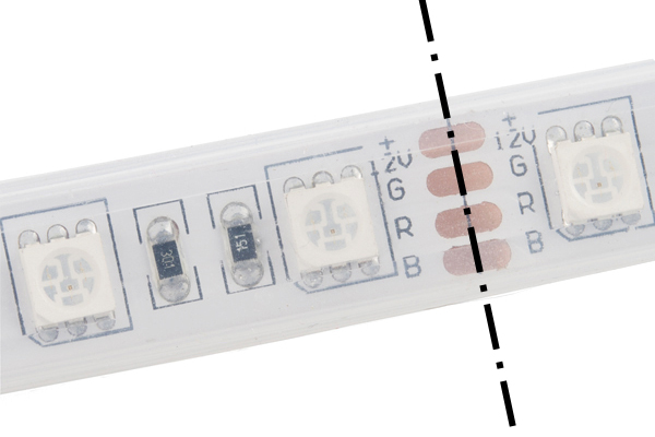
First, cut the LED strip at the center of the exposed pads using a diagonal cutter. The dot and dashed line in the image below is where you will need to perform the cut. Make sure to remove part of the silicone tube to access the LED strip's pads if you are using the sealed version.
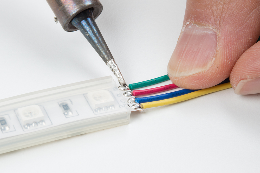
Cut half of the premium jumper wires and strip the insulation. Then solder the wires to each of the LED strip's pads.
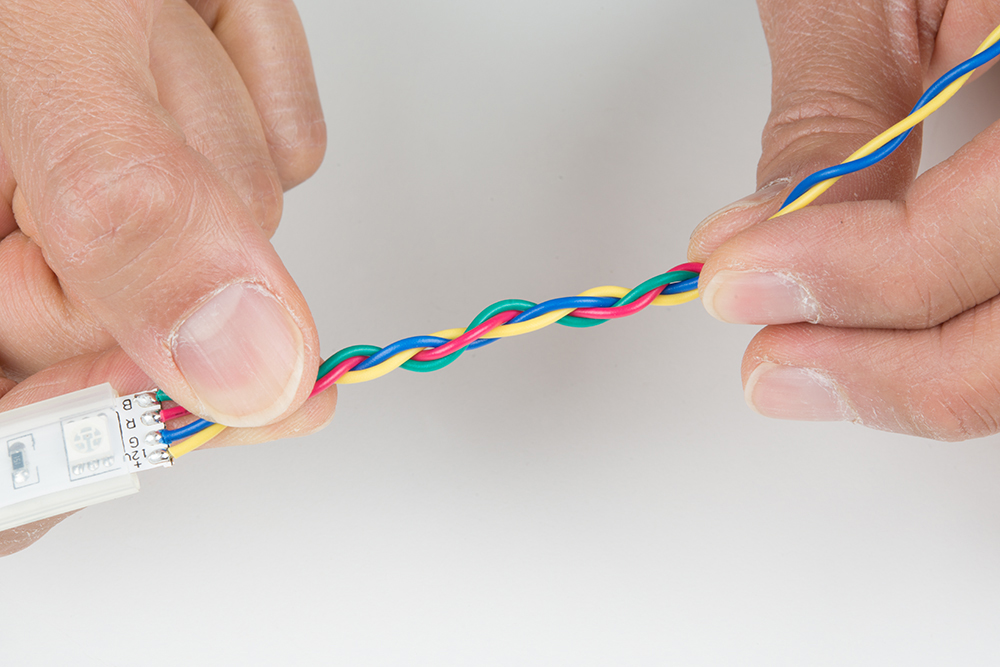
For a secure connection, you can braid the wires together to manage the connections. To braid your wires, twist a pair of wires in a counterclockwise pattern between your index finger and thumb using both hands. We'll be using the green and red wires that were soldered on.

Then twist the other pair of wires in a counterclockwise pattern.

Twist the pairs of wires in a clockwise pattern.
Clean Solder Joints
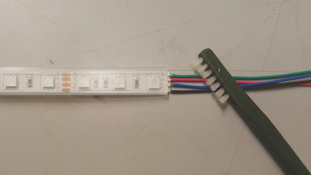
If you were using water soluble flux, clean the solder joints with deionized water and a toothbrush. Dry the LED strips thoroughly using compressed air. Luckily, SparkFun has a PCB cleaning room. As an alternative, you could use water from the sink and towels. You can also use isopropyl alcohol.
Test LED Strips
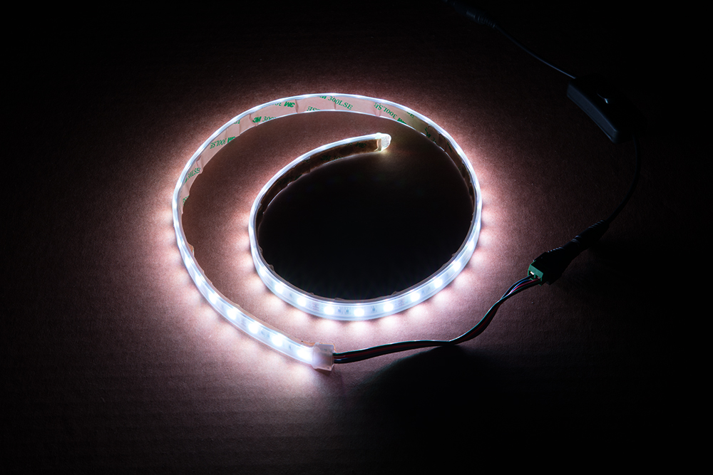
Once dry, test the LED strips to ensure the colors are correct and the wires are connected to its respective pads. You can use a benchtop power supply set to output about 12V, a 12V wall adapter, or 9V battery to verify the connection. The image below shows all the channels turned on. Make sure to test each channel individually.
Secure w/ Hot Glue or Heat Shrink
Add hot glue to the terminals to secure the wires further. You can also use some heat shrink with hot glue as long as it does not cover the LED. The image below shows the wires being secured with hot glue. The LED strip was used with a silicone tube so additional hot glue was added to seal the exposed strip.

Large Installation
For large installation projects, there may be voltage drops depending on the:
- amount of LEDs connected
- length of LED strip used
- how bright the LEDs are set
- animation
You may notice LEDs not able to fully turn on after a certain length due to the voltage drop. This is due to the increased resistance as you move further away from the power supply. You may notice that not all the colors are turned on or the strip becomes dim. You can also check the voltage after each meter using a multimeter to see if there are any voltage drops if you are not able to visually see the voltage drops. If you see voltage drops and the LED strip not properly turning on, you will need to inject power with the power supply between each LED strip's Vcc and GND after about 1, 2, or 5 meters.
Long lengths of LED strips can also pull a lot of current when fully turned on. If you are using a high amperage power supply with long lengths, make sure that there is enough air flow, a heat sink to dissipate the heat properly, and the wires can support the amperage. You may want to lower the brightness setting.
Resources and Going Further
Now that you've successfully got your non addressable LED strip up and running, it's time to incorporate it into your own project! For more information, check out the resources below:
- Datasheet (PDF) - 5060 LED that are populated on the LED strips
- GitHub Code Repo
Need some inspiration for your next project? Check out some of these related tutorials:
Prototype Wearable LED Dance Harness
Motion Controlled Wearable LED Dance Harness
Interactive 3D Printed LED Diamond Prop
Light Up Your 3D Printer's Bed
Or try adding a button, potentiometer, or sensor to control the LEDs. Here are a few examples to control an individual RGB LED with different languages.
SparkFun Inventor's Kit for Photon Experiment Guide
SparkFun Inventor's Kit for micro:bit Experiment Guide
Getting Started with MicroPython and the SparkFun Inventor's Kit for micro:bit
SparkFun Inventor's Kit Experiment Guide - v4.1
Or check out some of these blog posts for ideas: