MicroView Digital Compass
Introduction
In this tutorial you will learn how to use a MAG3110 3-axis magnetometer to make a portable digital compass! This project will also use the SparkFun MicroView to display the heading.
If you haven't checked it out already, go see the new MAG3110 Hookup Guide to learn how this device works!
Required Materials
This project uses the MAG3110 magnetometer to sense magnetic north along with the SparkFun Microview to display and control the whole show. If you don't have one, you will need a MicroView Programmer as well to upload code to the MicroView.
Since the MicroView is a 5V logic device and the MAG3110 is lower voltage device, you will also need a Bi-Directional Logic Converter to facilitate communication between them. Be careful, if you hook them up directly to each other, you could damage the MAG3110 sensor!
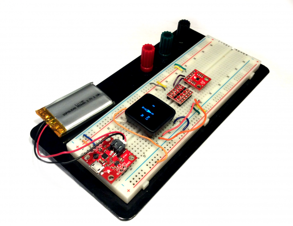
I chose to make the whole thing battery-powered, so I could walk around with it. I used SparkFun's Power Cell - LiPo Charger/Booster and an 850mAh LiPo Batter. However, feel free to keep it tethered to your computer over USB if you don't want to get the extra parts.
You can build the whole thing on a breadboard or use SparkFun's nifty snappable protoboard for a more permanent project.
For most of these parts, you may have to solder on male headers for use with a breadboard. See the suggested reading below for tips on how to do this!
The wish list below contains most of the parts you'll need to follow along.
Suggested Reading
Before embarking upon this guide, you may want to familiarize with any of the topics below.
Hardware Hookup
It might seem complicated, but there are only a few basic blocks of the circuit: power, brains, the level-shifter, and the sensor.
Powering your circuit
If you aren't using battery power you can just ignore the PowerCell. Be sure to only power the MAG3110 with 3.3V. If you give it 5V, it might get damaged! The MicroView has an internal 3.3V regulator, but unfortunately it isn't pulled out to the pins. Instead, you can use an external 3.3V LDO regulator. See the datasheet for how to hook this up (it's really simple!).
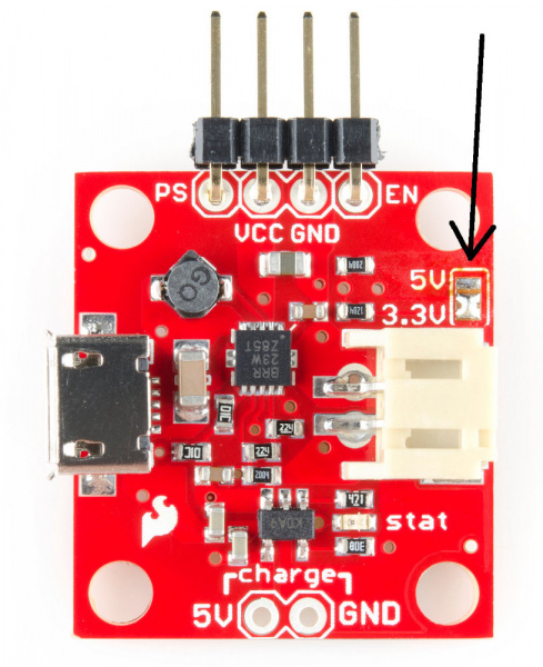
The PowerCell features a selectable voltage output -- either 5V (default) or 3.3V. In order to use it with our project, we need to change the output to 3.3V. There is a solder jumper that selects this. Use some solder wick to remove the solder, and bridge the center pad and the pad that says "3.3V".
If you are still unsure about your connection, see the PowerCell Quickstart Guide.
With either method, make sure to check the voltage output of your power source using a multimeter before you hook anything up to it!
Wiring up the MicroView
The MicroView has an internal 5V boost regulator. This means you can give it lower supply voltages (down to 3.3V) and it will boost them up to the 5V it needs. This makes it very easy to power our MicroView from the 3.3V output of the PowerCell.
Conveniently, the MicroView brings this 5V out to an external pin for use in other parts of our circuit. This is good because we need it to use the logic level shifter.
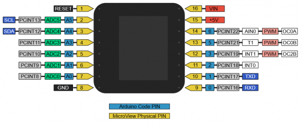
Recall the pinout of the MicroView:
Connect the 3.3V source to the VIN pin of the MicroView, and connect the GND pin to ground. Voila! The MicroView has power.
Connecting the level shifter
The level shifter allows higher voltage (5V) logic devices to talk to lower voltage (3.3V) logic devices without damage or miscommunication. For more information on logic levels, see this guide, and, to learn more about how to hook up the level shifter, see this guide
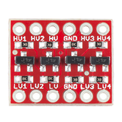
Here's the level shifter we will be using:
Notice there's a high voltage side and a low voltage side. Connect the high voltage source, "HV", to the 5V pin of the MicroView, and connect GND to ground.
For the low voltage side, connect LV to 3.3V and GND to ground.
I2C Communication
The MAG3110 sensor communicates over I2C. This protocol is nice because it only requires two wires between the devices. Namely, SDA (serial data) and SCL (serial clock). From the pinout shown before, you can see the MicroView has SCL and SDA on pins 2 and 3, respectively.
We only have to shift these two outputs, so connect the SCL and SDA of the MicroView to HV1 and HV2 of the level shifter.
Wiring the MAG3110 Sensor
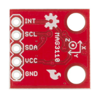
The MAG3110 sensor is a 3-axis magnetometer that can be used to sense the strength of magnetic fields. This data can be used to find magnetic north! Check out the MAG3110 hookup guide for more on how to use this sensor!
The MAG3110 breakout only has a few pins we need to connect.
The MAG3110 can only handle voltages up to 3.6V, so be sure to connect VCC to 3.3V and not 5V. The GND pin goes to ground, and SCL and SDA should go to LV1 and LV2 of the level shifter. Make sure you don't have SCL or SDA swapped around on either side of the level shifter or you won't be able to talk to the sensor.
Completed Circuit
The circuit should now be complete. Make sure to check your connections before you plug in the battery.
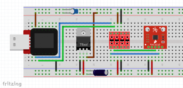
If you chose to use USB power (using the MicroView Programmer) and an external 3.3V regulator, this circuit is found below. Don't worry too much about the capacitors, they're just filtering capacitors recommended by the regulator's datasheet.
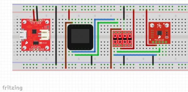
If you used the more portable battery-based PowerCell circuit, you can follow this circuit shown below.
MicroView Sketch
Now that the circuit is complete, it's time to program the MicroView! If you haven't already, go check out the MAG3110 Hookup Guide, and download the SparkFun MAG3110 Arduino library. This library makes it super easy to use the MAG3110 sensor and includes the example digital compass sketch we're about to use.Not sure how to install an Arduino library? Check out this guide!.
Once the library is installed, you can find the code for the digital compass under Examples → SparkFun MAG3110 Magnetometer Breakout Arduino Library → SparkFun_DigitalCompass.
The code is basically the example calibration code and also manages the sprite rendering.
Getting Sprites on the MicroView
Rendering sprites on the MicroView can be a bit of a challenge. I wrote a small Processing sketch to convert bitmaps to hex code that can be displayed more easily on the MicroView. It's not very polished but you can download that using the link below, or you can find the Files in the MAG3110 Arduino Library GitHub repo.
You may need to install the Processing sDrop library. If you need help with Processing, see this guide.
When you run the sketch, a virtual MicroView will appear on your screen. Drag any bitmap file (up to 64X48 pixels) into the virtual MicroView and it will convert it to hex. Note that all the pixels need to be white or black. You should see a preview in the virtual MicroView.
Copy the hex output from the Processing console, and copy it into your code. You can now load this hex into the MicroView screen buffer, and it should display it properly. You may need to format the hex (and get rid of extra commas) for it to compile properly.
Understanding and Running the Sketch
In the beginning of the code, you will see a lot of the word PROGMEM. Since this sketch uses a lot of sprites, the regular memory couldn't hold all of them. This keyword is part of a library that lets you store certain variables in memory.
The rest of the code follows the example calibration sketch for the MAG3110 Library. If you want to know more about calibrating the MAG3110, see the hookup guide linked to earlier. The heading I get from this I had to offset by 90 degrees since the MicroView and the MAG31110 x-axis were pointing in different directions.
When you first start running the sketch, you will need to calibrate the MAG3110 by spinning it 360 degrees a few times while keeping it level.
Based on the heading, the code loads a different sprite onto the MicroView.
Once calibrated, you should have a working digital compass!
Resources and Going Further
There are a many more cool projects you can make with the MAG3110 sensor. If you combine the MAG3110 with a few other sensors, you can make a variety of projects that involve location and orientation sensing.
Check out Shawn Hymel's Adventues in Science: Using a Magnetometer as a Compass and example code for ideas:
For more sensor fun, check out these other great SparkFun tutorials:
