Bi-Directional Logic Level Converter Hookup Guide
 jimblom
 Introduction
Do you have a 3.3V I2C or SPI sensor that might go up in smoke if connected to a 5V Arduino? Or a 5V device that needs a workaround to be compatible with your 3.3V Raspberry Pi 4, Raspberry Pi Zero, RedBoard Turbo, RedBoard Turbo or Arduino Due?
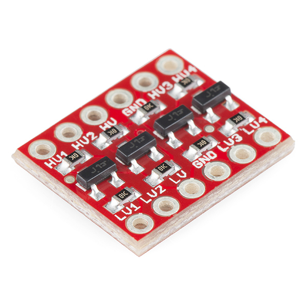
To get over this obstacle you need a device that can shift 3.3V up to 5V or 5V down to 3.3V. This is called logic level shifting. Level shifting is a dilemma so common we designed a simple PCB assembly to make interfacing devices a little easier: the Bi-Directional Logic Level Converter.
Though they're share the same shape and size, this bi-directional logic level converter shouldn't be confused with the more "uni-directional" version. This converter can pass data from high to low and/or low to high on all channels. It's perfect for level-shifting between devices that are sharing a data wire, like I2C or a one-wire interface.
Covered In This Tutorial
In this tutorial we'll take an in-depth look at the Bi-Directional Logic Level Converter. We'll examine the schematic and board layout -- explaining what each pin on the board does. At the end we'll go over some hookup examples to show how you might hook the board up for various interfaces.
Suggested Reading
If you aren’t familiar with the following concepts, we recommend checking out these tutorials before continuing.
How to Solder: Through-Hole Soldering
Working with Wire
How to Use a Breadboard
What is an Arduino?
Logic Levels
Board Overview
If you take a peek at the board's schematic, you'd find that the bi-directional logic level converter (let's shorten that to BD-LLC) is actually a very simple device. There is basically one level-shifting circuit on the board, which is repeated four times to create four level-shifting channels. The circuit uses a single N-channel MOSFET and a couple pull-up resistors to realize bi-directional level shifting.
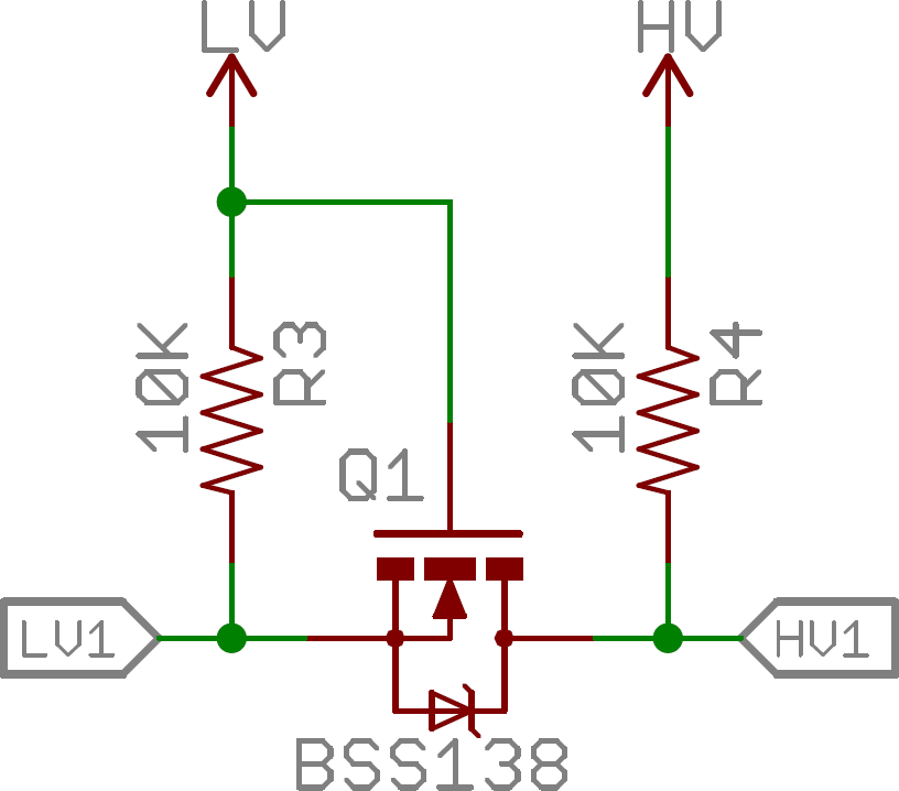
Through some semiconductor magic, this circuit can shift a low voltage signal to high and/or shift a high-voltage signal to a low voltage. A 0V signal on one end remains a 0V signal on the other. For a complete analysis of this circuit, check out this excellent Philips Application Note AN97055.
The Pinout
There are 12 total pins on the BD-LLC -- two parallel rows of six headers. One row contains all of the high voltage (e.g. 5V) inputs and outputs, the other row has all things low voltage (e.g. 3.3V).
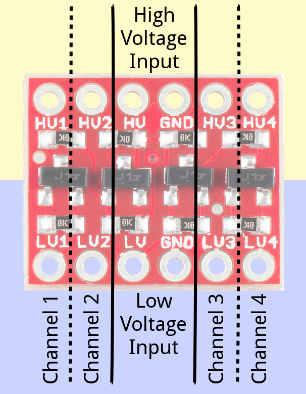
The pins are labeled on both the bottom and top sides of the board, and organized into groups. Let's look closer at some of the pin groups:
Voltage Inputs
The pins labeled HV, LV, and two GND's provide high and low voltage references to the board. Supplying a steady, regulated voltage to both of these inputs is required.
The voltage supplied to the HV and GND inputs should be higher than that supplied to the LV side. For example, if you're interfacing from 5V to 3.3V, the voltage on the HV pin should be 5V, and the voltage on LV sould be 3.3V.
Data Channels
There are four separate data channels on the BD-LLC, each capable of shifting data to and from high and low voltages. These pins are labeled HV1, LV1, HV2, LV2, HV3, LV3, HV4, and LV4. The number at the end of each label designates the channel of the pin, and the HV or LV prefix determines whether it's on the high or low side of the channel.
A low-voltage signal sent in to LV1, for example, will be shifted up to the higher voltage and sent out HV1. Something sent in HV3 will be shifted down and sent out of LV3. Use as many of these channels as your project requires. You don't have to use every single one.
Keep in mind that these level shifters are purely digital. They can't map an analog voltage from one max voltage to another.
Hookup Examples
Assembly
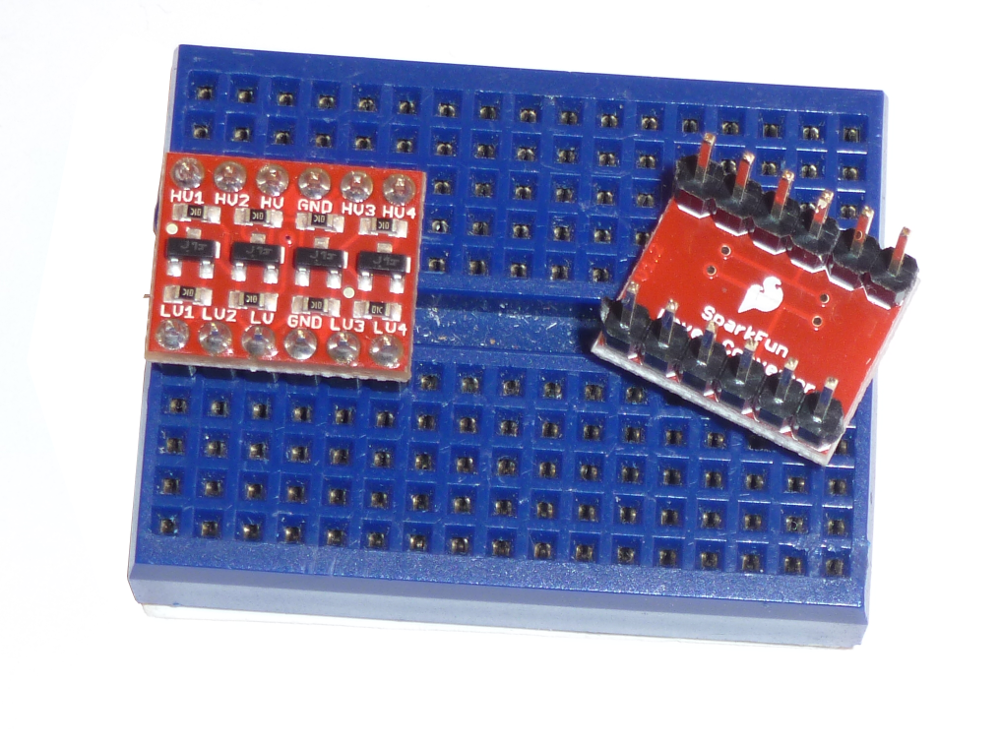
Before you can plug the converter into your system, you’ll need to solder something into it. There are a lot of options here. You could solder straight male headers in, and plug it right into a breadboard. Or perhaps you want to solder wires directly into it. Pick an assembly method that melds with how you intend to use the board.
Once your BD-LLC is soldered up, it's time to hook it up. Your hookup will probably vary depending on which communication interface you're using. Below we'll show how to hook the level converter for three of the most common communication protocols.
Using the BD-LLC for Serial
Although you won't be taking advantage of the BD-LCC's bi-directional abilities, it's perfectly fine to use the board to shift serial communication. Serial usually requires two signal wires -- RX (receive) and TX (transmit) -- which both have a defined direction. These signals can be passed through any of the four channels on the BD-LLC.
Let's say, for example, you want to hookup an Electric Imp Breakout Board (which has a 3.6V maximum input voltage) to an Arduino Uno via their UARTs. Here's one possible hook up:
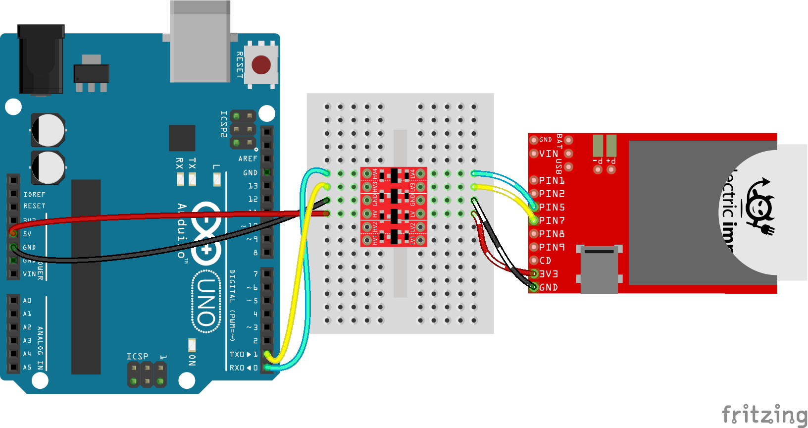
Make sure LV is powered at 3.3V, and HV is at 5V. Double-check that the channels match up, and a-shifting you will go! You've even got two extra channels to shift as you please.
Using the BD-LLC for SPI
The BD-LLC's four channels are a perfect match for most SPI communications. SPI usually requires four wires: MOSI (master out, slave in), MISO (master in, slave out), SCLK (serial clock), and CS (chip select). These four wires can each be routed through a channel on the BD-LLC.
For example, if you wanted to connect an Arduino to an ADXL345 Breakout Board, which has an operating range of 2.0-3.6V, here's how the BD-LLC could be spliced in:
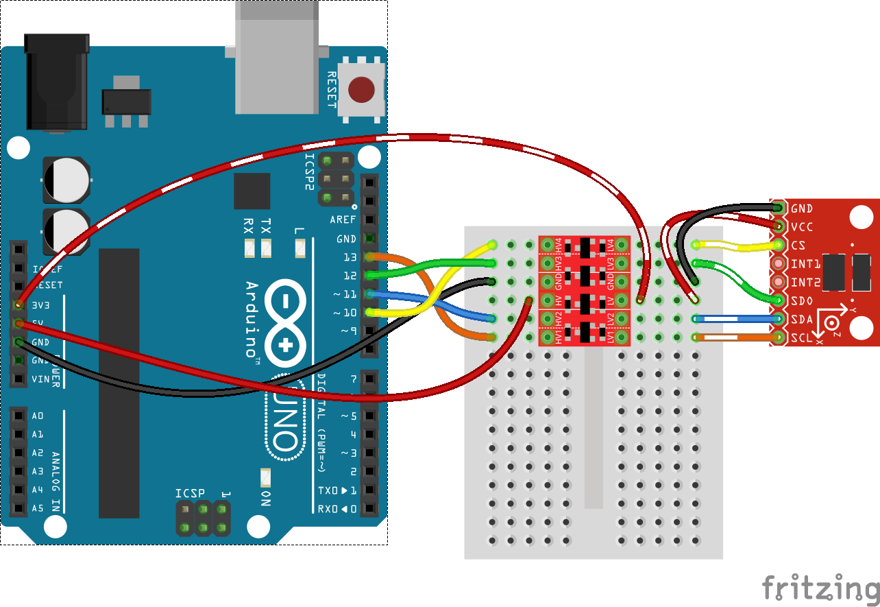
Since each of the channels on the BD-LLC are bi-directional any of the four SPI lines can go through any of the BD-LLC's four channels.
Using the BD-LLC for I2C
I2C is the communication standard where the BD-LLC really shines, because it requires that both data and clock signals -- SDA and SCL -- be bi-directional. Each of those lines can be passed through any of the BD-LLC's level-shifting channels.
For this example, let's keep using the ADXL345 breakout but instead swap over to the I2C interface. We can even add another I2C device...how about the L3G4200D Gyroscope Breakout. Since I2C is only a two-wire interface, we have room on the BD-LLC to fit in a couple of extra signals, like the interrupt outputs from each board
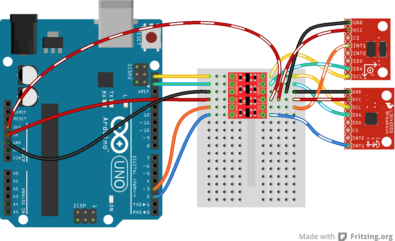
The two 3.3V I2C devices can both share the same level shifted SDA and SCL lines. Even more I2C device can be added, as long as they have unique addresses.
Resources and Going Further
Here are some resources related to the LLC and level-shifting in general:
- Schematic (PDF)
- Eagle Files (ZIP)
- Philips AN97055 (PDF) -- An awesome application note covering bi-directional level shifting circuits.
- GitHub Repo
- SFE Product Showcase
If you're looking for a place to use the LLC, these tutorials might spark some ideas:
- Using the Arduino Pro Mini 3.3V -- If you want to stick with Arduino, and want to use 3.3V sensors, consider using an Arduino that runs at 3.3V. That way you won't even need to bother with an LLC!