MAG3110 Magnetometer Hookup Guide
 AGlass0fMilk
Introduction
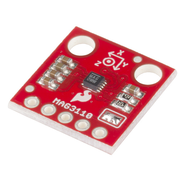
The SparkFun MAG3110 Triple Axis Magnetometer is a breakout board for the 3-axis magnetometer from NXP/Freescale. It is a low power (1.95V to 3.6V) device that communicates over I2C. It outputs data in two's complement with values ranging from -30,000 to +30,000 and has a full-scale range of ±1000µT.
This sensor allows you to quickly detect surrounding magnetic fields. This data can be used to create a digital compass or even sense strong magnetic fields from transformers!
We will explore the functions of the MAG3110 sensor and get up and running using the SparkFun MAG3110 Arduino library and example code.
Required Materials
The required materials varies depending on how you want to use the sensor. You will notice this sensor's supply can only go up to 3.6V. If you try to communicate with this sensor using a 5V Arduino or similar platform you could permanently damage the chip! To use this with 5V logic devices, you must use a bi-directional logic level converter.
Fortunately, SparkFun offers a few inexpensive options. This part is recommended.
Please note you will also need a low voltage source to power this sensor if your Arduino does not have an on-board regulator. You may want to use something like this 3.3V Low-Dropout Regulator (LDO)
For the rest of the items you will need, see the wish list below.
Suggested Reading
Before embarking upon this guide, you may want to familiarize with any of the topics below.
- I2C
- Through Hole Soldering (And Hot Tips on Soldering Headers!)
- Bi-Directional Logic Converter Hookup Guide
- Binary
- Interrupts
- Magnetic Fields
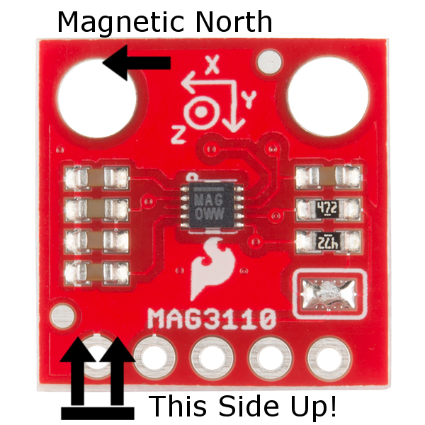
Hardware Overview
MAG3110 Details:
- 3 magnetic field channels
- 1.95V to 3.6V supply voltage
- Full-scale range of ±1000 µT
- Sensitivity of 0.10 µT
- Output data rates up to 80Hz
- I2C Serial Interface
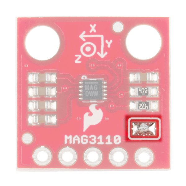
Pull-up Resistors
As with other SparkFun breakout boards using I2C, this sensor features on-board pull-up resistors to make getting started quick and easy. However, you may need to disconnect these pull-ups when using other devices on the I2C bus that also have these pull-ups. You can disconnect these by using some solder wick to remove the solder from the pads on the front of the board highlighted in the image below.
Pin Functions
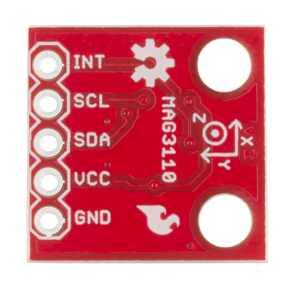
The MAG3110 breakout doesn't have many pins, which makes it very easy to hookup! You just need to give it a supply voltage up to 3.6V(VCC), ground (GND), and the I2C bus lines for communication. These are the SDA and SCL pins.
| Symbol | Description |
|---|---|
| VCC | Supply Voltage (1.95V to 3.6V) |
| GND | Must be connected to ground |
| SDA | Serial Data pin for I2C Communication |
| SCL | Serial Clock pin for I2C Communication |
| INT | Interrupt pin -- high when new data is ready |
You may notice there is one last pin -- the INT pin. This stands for INTerrupt. Inside the MAG3110 there is a register that can tell you if the sensor has new data for you to read. The INT pin is hard-wired to this register and outputs a logic high when new data is ready. When you read data from the sensor this register is automatically cleared to 0.
While you can just continuously read values from the sensor regardless of whether it's new, this is inefficient both in terms of power and processor cycles. A better way is to trigger reading data when this pin goes high. But if all you want to do is get a reading and don't care about efficiency, then don't worry about connecting this pin!
If you are an advanced user, the INT pin can be setup by using an external interrupt. Note that I found this difficult to achieve without weird results. I believe the Arduino Wire (I2C) or Serial libraries use interrupts and it conflicts with this. If you are using a different platform, it may work better.
Hardware Assembly
As mentioned before, if you are using this sensor with a 5V Arduino or other microcontroller, you will need to have a logic level converter between the microcontroller and the sensor.
If you are unsure how to hook up a logic level converter, see this guide.
You will also need to step down the supply voltage to a suitable level for this sensor. Some microcontrollers (like the Arduino Micro and SparkFun RedBoard) have built in 3.3V regulators that you can use to power the MAG3110!
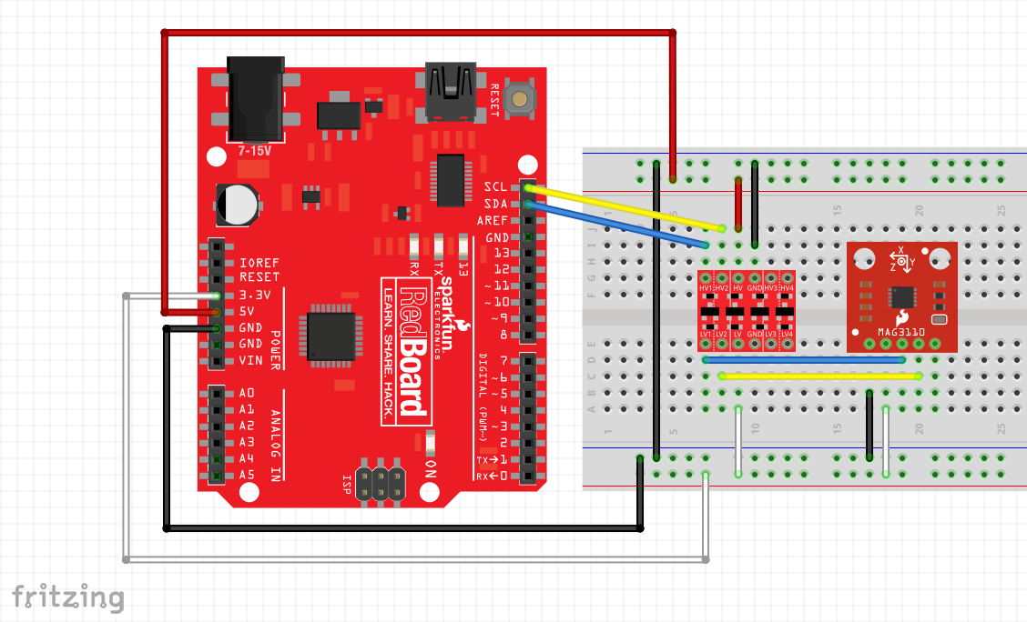
As an example, here is how to connect the MAG3110 sensor to a SparkFun RedBoard.
The pins should be connected as follows:
| RedBoard Pin | Logic Converter Pin | MAG3110 Pin |
|---|---|---|
| 3.3V | LV | VCC |
| GND | GND | GND |
| 5V | HV | - |
| SDA | HV1 | - |
| SCL | HV2 | - |
| - | LV1 | SDA |
| - | LV2 | SCL |
Here is this circuit laid out on a breadboard:
If you're not using a SparkFun RedBoard, the only pins that will change are the SDA and SCL. For other Arduino boards, SDA and SCL are:
| Board | I2C Pins |
|---|---|
| Uno, Ethernet | A4 (SDA), A5 (SCL) |
| Mega2560 | 20 (SDA), 21 (SCL) |
| Leonard/Micro | 2 (SDA), 3 (SCL) |
| Due | 20 (SDA), 21 (SCL), SDA1, SCL1 |
SparkFun MAG3110 Library
SparkFun has created a library to make it easier to get readings from the MAG3110 sensor. It also has code to calibrate the sensor and obtain magnetic north headings!
Note: The calibration and magnetic north readings only work if the magnetometer is oriented level with the z axis pointing up or down! Obtaining magnetic north independent of orientation requires the use of an accelerometer to know which way is down and more complex math.
You can download the library here along with example code. You can find the latest library and example files in the GitHub repository for this library. Not sure how to install an Arduino library? Check out this guide!
There are a variety of functions beyond basic readings. To learn more, browse through the included examples in the library. You can also look at the library source code. We'll go over a few of the basic commands in this guide.
Using the Library
Once you have the library installed, open the included example SparkFun-MAG3110-Basic.ino.
This sketch is bare-bones way of reading data from the MAG3110.
language:c
#include <SparkFun_MAG3110.h>

MAG3110 mag = MAG3110(); //Instantiate MAG3110

void setup() {
  Serial.begin(9600);

  Wire.begin();             //setup I2C bus
  Wire.setClock(400000);    // I2C fast mode, 400kHz

  mag.initialize(); //Initializes the mag sensor
  mag.start();      //Puts the sensor in active mode
}

void loop() {

  int x, y, z;
  //Only read data when it's ready
  if(mag.dataReady()) {
    //Read the data
    mag.readMag(&x, &y, &z);

    Serial.print("X: ");
    Serial.print(x);
    Serial.print(", Y: ");
    Serial.print(y);
    Serial.print(", Z: ");
    Serial.println(z);

    Serial.println("--------");
  }
}
Calling mag.initialize() sets up the sensor and checks whether a MAG3110 is connected properly. If mag.error is true, the Arduino was unable to talk to the MAG3110! When initialized, the magnetometer is set to standby mode with all offsets set to 0. To put the magnetometer in active mode and start sampling, simply write mag.start()
You can check whether any new data is ready using the mag.dataReady() function. This will return true if new data is available.
You can read all three axes using the mag.readMag() function. Don't be afraid of the & symbol! This simply means we are giving the address of the variables to the function so that they can be filled with the data. If this seems confusing, you might want to read about pointers.
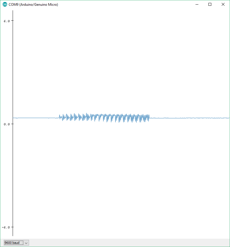
If you run this sketch and open up Tools->Serial Monitor, you should see the following:

Other functions can be seen in the SparkFun-MAG3110-Other.ino sketch:
language:c
#include <SparkFun_MAG3110.h>

MAG3110 mag = MAG3110(); //Instantiate MAG3110

void setup() {
  Serial.begin(9600);

  Wire.begin();             //setup I2C bus
  Wire.setClock(400000);    // I2C fast mode, 400kHz

  mag.initialize();
  //This line makes the output data rate a lot slower
  //Output Data Rate = 1.25Hz
  //Oversampling Ratio = 32
  //This means it takes 32 samples and averages the results
  if(!mag.error) //You can use this to check if there was an error during initialization.
  {
    mag.setDR_OS(MAG3110_DR_OS_1_25_32);
    mag.start();
  }

  //You can set your own offsets without calibration
  //mag.setOffset(MAG3110_X_AXIS, -100);
  //mag.setOffset(MAG3110_Y_AXIS, 300);
  //mag.setOffset(MAG3110_Z_AXIS, -300);

  //You can read the sensor's offset by calling:
  //int offset = mag.readOffset(MAG3110_X_AXIS);

  //You can obtain system information by calling any of the following:
  //mag.isActive(); //Tells you whether the mag sensor is active or in standby
  //mag.isRaw(); //Tells you if the mag sensor is outputting raw data or not
  //mag.isCalibrated(); //Tells you if the mag sensor has been calibrated
  //mag.isCalibrating(); //Tells you if the mag sensor is currently being calibrated
  //uint8_t mode = mag.getSysMode(); //Reads the SYSMOD register. See the datasheet for more information

  //This will reset the sensor to default values
  //It sets the offsets to 0, flags it as uncalibrated, and sets the device to standby mode
  //The Output Data Rate and Oversampling ratio will also be set to 80 and 16 respectively (see datasheet)
  //mag.reset();

  //This will disable the use of user offsets
  //User offsets are enabled by default but are initialized to 0
  //mag.rawData(true);
}

void loop() {

  float xf, yf, zf;
  //Only read data when it's ready
  if(mag.error)
    Serial.println("Could not connect to MAG3110 Sensor!");
  if(mag.dataReady()) {
    mag.readMicroTeslas(&xf, &yf, &zf); //This divides the values by 10 to get the reading in microTeslas

    Serial.print("X: ");
    Serial.print(xf);
    Serial.print(", Y: ");
    Serial.print(yf);
    Serial.print(", Z: ");
    Serial.println(zf);

    Serial.println("--------");
  }
}
A few functions to point out from the example above:
mag.setDR_OS() - This functions allows you to set the MAG3110's Output Data Rate (ODR) and Over-sampling Ratio (OSR). The output data rate tells you how many new datasets the MAG3110 will provide in one second. For example, an output data rate of 80 (the default) will give you 80 new readings per second. The over-sampling ratio tells the MAG3110 how many samples to average together for one reading. For example, with an OSR of 16 the MAG3110 will take 16 measurements, average the results together, and give you one averaged result.
These two variables are related, and you can find more about this setting in the datasheet. The library includes defined settings for this that follow this format: MAG3110_DR_OS_80_16. This will give you an ODR of 80Hz and an OSR of 16.
mag.setOffset(axis, offset) - This allows you to set your own offsets in case you have calibration data saved. You can choose which axis to change using these defined constants: MAG3110_X_AXIS, MAG3110_Y_AXIS, MAG3110_Z_AXIS.
mag.readOffset(axis) - This allows you to get the offsets the MAG3110 is using. You could use this function to save the offsets after calibration!
Note: If you want to fully save calibration data, you will have to save mag.x_scale and mag.y_scale. These are both float values that are calculated during calibration. Be sure to only modify these values when you have saved calibration data or you may have to recalibrate! You can also directly set mag.calibrated to true if you manually calibrate the sensor
mag.isActive() - Tells you whether the mag sensor is active or in standby
mag.isRaw() - Tells you if the mag sensor is outputting raw data or not
mag.isCalibrated() - Tells you if the mag sensor has been calibrated
mag.isCalibrating() - Tells you if the mag sensor is currently being calibrated
mag.getSysMode() - Reads the SYSMOD register. See the datasheet for more information
mag.rawData(boolean) - This sets whether the MAG3110 will output raw (non-user corrected) or offset data. Giving the function a true value will set the data to raw output, and vice-versa.
mag.readMicroTeslas() - This gives data in µTeslas. It really just divides the normal output by 10 since this is the scale the MAG3110 uses.
There are additional functions shown in other example sketches included with the library. A few of these are:
mag.readRegister(address) - This allows you to read any register of the MAG3110. Read the datasheet for more information. The library has all registers mapped in the format MAG3110_REGISTER_NAME.
mag.writeRegister(address, value) - This allows you write a value to any register of the MAG3110. Be careful if you aren't sure what you're doing! You might change settings you didn't mean to!
mag.triggerMeasurement() - When the MAG3110 is in standby, this triggers a single measurement to take place. It lets you save power by keeping the device mostly inactive and only take data when you need to. Be aware this single-shot reading may be less accurate than active mode reading since the signal takes time to settle. See the datasheet for more information. If you want to learn how to do triggered measurements, see the included example "SparkFun-MAG3110-Triggered".
You can also do triggered measurements while in active mode. This is more advanced and is covered in the datasheet.
Calibration
All these functions are great... but what if you need to find a portal to The Upside Down? You need a heading! This sensor and library allow you to obtain the magnetic north heading very easily!
Note that this only works when the sensor is level with the z-axis pointing straight up or down. The heading will be relative to the positive x-axis (ie: the x-axis arrow silkscreened on the board points to magnetic north).
To find out how to use the library's calibration, open up the included example sketch, SparkFun-MAG3110-Calibration.ino.
When you run the sketch, you will see unadjusted readings in the Serial output for the first 5 to 10 seconds. During this period, you must rotate the MAG3110 360 degrees while keeping it level!. This allows our sketch to get its bearings.
The reason for calibration is that your surroundings may have static magnetic fields that offset the MAG3110 readings. For example, if you have something magnetic near the sensor this will add an offset to the sensor's readings.
This calibration code will center the x and y-axis readings around 0 or about there. The z-axis is not calibrated with this library. This calibration works by taking a bunch of readings and trying to find the minimum and maximum values for the x and y axes. It then uses these min and max values to calculate an offset and a scaling factor. The calibration code is based off of this code found here.
A Honeywell application note detailing how the heading is calculated can be found here.
language:c
#include <SparkFun_MAG3110.h>

MAG3110 mag = MAG3110(); //Instantiate MAG3110

void setup() {
  Serial.begin(9600);

  Wire.begin();             //setup I2C bus
  Wire.setClock(400000);    // I2C fast mode, 400kHz

  mag.initialize(); //Initialize the MAG3110
}

void loop() {

  int x, y, z;

  if(!mag.isCalibrated()) //If we're not calibrated
  {
    if(!mag.isCalibrating()) //And we're not currently calibrating
    {
      Serial.println("Entering calibration mode");
      mag.enterCalMode(); //This sets the output data rate to the highest possible and puts the mag sensor in active mode
    }
    else
    {
      //Must call every loop while calibrating to collect calibration data
      //This will automatically exit calibration
      //You can terminate calibration early by calling mag.exitCalMode();
      mag.calibrate();
    }
  }
  else
  {
    Serial.println("Calibrated!");
  }
  mag.readMag(&x, &y, &z);

  Serial.print("X: ");
  Serial.print(x);
  Serial.print(", Y: ");
  Serial.print(y);
  Serial.print(", Z: ");
  Serial.println(z);

  Serial.print("Heading: ");
  Serial.println(mag.readHeading());

  Serial.println("--------");

  delay(100);
}
Note a few things about the calibration functions.
Setting the MAG3110 to calibration mode (ie: using mag.enterCalMode()) will set it to the highest output data rate and enter active mode. You will need to set your desired ODR and OSR after calibration, and enter standby if you wish. If you just want to simply read values, you can leave these settings alone.
When calibrating, you must call mag.calibrate() every loop cycle. This allows the code to sample the MAG3110 readings and find the minimum and maximum values.
The calibration mode will automatically exit after some time but at least 5 seconds. If this is too long, you can terminate the calibration earlier by calling mag.exitCalMode(). Please note that the calibration may be offset if you do not calibrate enough!
If you have not calibrated the MAG3110, calling mag.readHeading() will only give you 0! Otherwise, it will show values ranging from -180 to +180. When the heading is 0, the x-axis is pointing towards magnetic north (see the diagram from before).
As mentioned before, if you want to manually calibrate the MAG3110 using previously obtained calibration values, you need to do a few things: Save the offsets using mag.readOffset(), and save the scaling floats, mag.x_scale and mag.y_scale. When reloading this calibration, you have to use mag.setOffset() and write the old scaling factors back to mag.x_scale and mag.y_scale. For completeness, update the mag.calibrated value to true as well. Note that as the calibration data becomes outdated, recalibration is recommended.
Alternative Applications
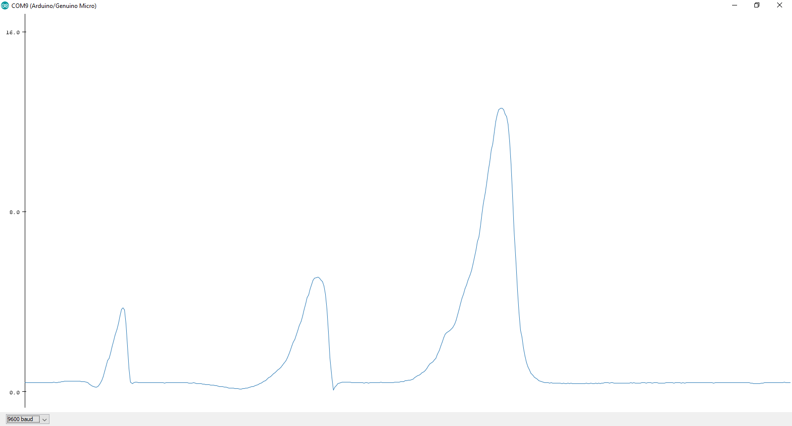
Aside from sensing magnetic north, this sensor has a few other uses. Many high power electronics create magnetic fields of their own. With this sensor, you can see this disturbance.
An example sketch is included with the library called SparkFun-MAG3110-Magnitude.ino. This sketch first calibrates the sensor and then outputs serial data of the magnitude of the scaled x and y-axes. Recall the magnitude of a vector is:

In this case a3 is 0 since we do not take the z-axis into account.
Once the sketch is running and calibration has completed, open up the Tools->Serial Plotter in the Arduino IDE (only available in the newest versions of the Arduino IDE). If you put the sensor near a microwave and then warm something up, you will see some noise on the signal.
And, if you put a fridge magnet near the sensor, you will see large spike! Be careful though, the sensor has maximum limits of magnetic field strength it can be exposed to without damage.
Resources and Going Further
This is a nifty little sensor for orientation, but you may want to go beyond the simple compass that this library allows. You can use an accelerometer in conjunction with this device to create a tilt-compensated compass. SparkFun has a variety of accelerometers available, including the ADXL345.
To get you started in the right direction, here are a few application notes that go into more detail about this:
You can also check out my project using this guide and the MAG3110, the Digital Compass.