Qwiic 9DoF - ISM330DHCX, MMC5983MA Hookup Guide
Introduction
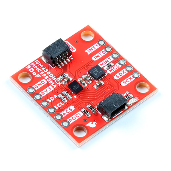
The SparkFun Qwiic 9DoF - ISM330DHCX, MMC5983MA combines the high-performance ISM330DHCX 3D digital accelerometer and gyroscope from STMicroelectronics with the highly sensitive triple-axis magnetometer by MEMSIC to give you an ultra powerful, easy to use, Qwiic enabled breakout board.
With a full scale acceleration range of ±2/±4/±8/±16 g and a wide angular rate range of ±125/±250/±500/±1000/±2000/±4000 dps, as well as an unmatched set of embedded features (Machine Learning Core, programmable FSM, FIFO, sensor hub, event decoding and interrupts), the ISM330DHCX delivers high performance at very low power. Add to that the MMC5983MA, which can measure magnetic fields within the full scale range of ±8 Gauss (G), with 0.25mG/0.0625mG per LSB resolution at 16bits/18bits operation mode and 0.4 mG total RMS noise level and you've got 9 Degrees of Freedom on one tiny little breakout board.
Required Materials
To follow along with this tutorial, you will need the following materials. You may not need everything though depending on what you have. Add it to your cart, read through the guide, and adjust the cart as necessary.
Suggested Reading
If you aren’t familiar with the following concepts, we recommend checking out these tutorials before continuing.
Logic Levels
Accelerometer Basics
I2C
Serial Terminal Basics
Hardware Overview
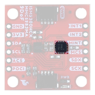
ISM330DHCX 6DoF
The ISM330DHCX is a small, system-in-package from STMicroelectronics featuring a high-performance 3D digital accelerometer and 3D digital gyroscope capable of wide bandwidth, ultra-low noise and a selectable full-scale range of ±2/±4/±8/±16 g. The 3D gyroscope has an angular rate range of ±125/±250/±500/±1000/±2000/±4000 dps and offers superior stability over temperature and time along with ultra-low noise.
The ISM330DHCX as implemented in the 9DoF can run in two different modes:
Mode 1
This is the default "peripheral only" mode. This mode allows you to use either I2C or SPI. By default, I2C is enabled with an address of 0x6B. By manipulating the associated jumper, you can change the I2C address to 0x6A (cut the power side and close the ground side) or switch to SPI mode (both jumpers open).
Mode 2
This mode enables a secondary I2C port that the 6DoF controls; up to 4 external sensors can be connected to the I2C controller interface of the device. External sensors communicate via the SCX and SDX (PICOX) lines - the SCX jumper will need to be opened.
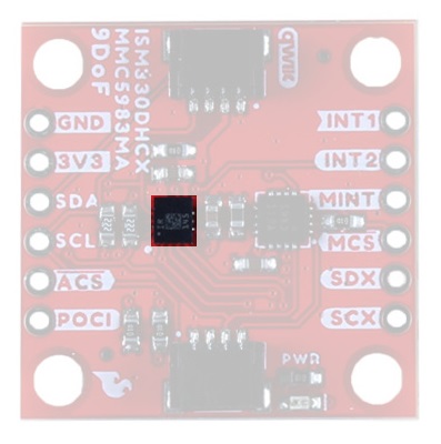
MMC5983MA
The MMC5983MA is an AEC-Q100 qualified, fully integrated 3-axis magnetic sensor with on-chip signal processing and integrated I2C/SPI bus. It has superior dynamic range and accuracy with ±8G FSR, 18bit operation, 0.4mG total RMS noise, and can enable heading accuracy of 0.5º. More information can be found in the datasheet.
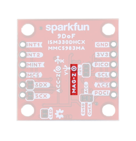
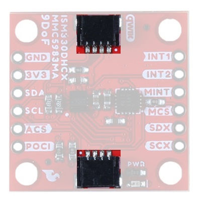
Qwiic Connectors
Our Qwiic Ecosystem makes sensors pretty much plug and play. There's a Qwiic connector on either side of the Qwiic 9DoF - ISM330DHCX, MMC5983MA breakout to provide power and I2C connectivity simultaneously. The default I2C address for the ISM330DHCX is 0x6B, and the I2C address for the MMC5983MA Magnetometer is 0x30.
Pins
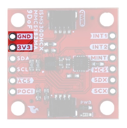
Power
Ideally, power will be supplied via the Qwiic connectors, but we've also broken out plated through hole pins to supply 3.3V and Ground, should you prefer. Make sure to pay attention to logic levels - supply voltage to this board should range from 1.71 V to 3.6 V.
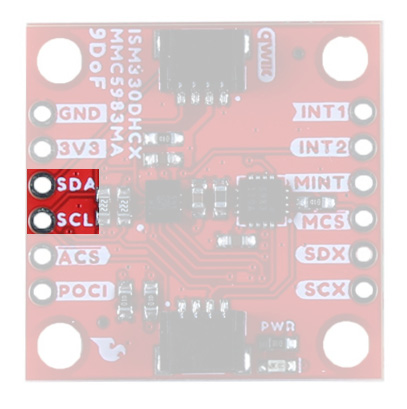
I2C
For flexibility, we've broken out the I2C functionality as seen below. Primary I2C pins are broken out to SDA and SCL:
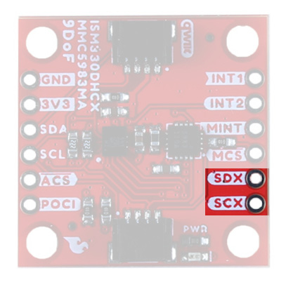
Secondary I2C pins are broken out to SDX and SCX. These pins are used solely for Mode 2- Sensor Hub Mode - where the ISM330DHCX reads other sensors. You must cut the SDX and SCX jumpers on the back of the board in order to use this mode.
SPI
Like the I2C functionality, we've also broken out the SPI functionality to PTH pins.
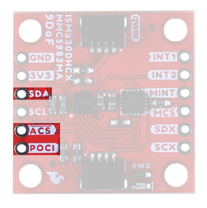
SPI Pins for the ISM330DHCX are broken out to SDA, POCI, and the ACS (Accelerometer Chip Select) highlighted here:
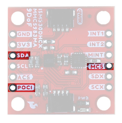
SPI pins for the MMC5983MA are broken out to SDA, POCI, and the MCS (Magnetometer Chip Select) highlighted here:
Interrupt
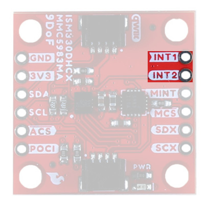
Interrupt functionality for the 6DoF accelerometer is available via two PTH pins - INT1 and INT2. INT2 can be configured to an Input/Output pin and can be used to synchronize data for Sensor Hub Mode.
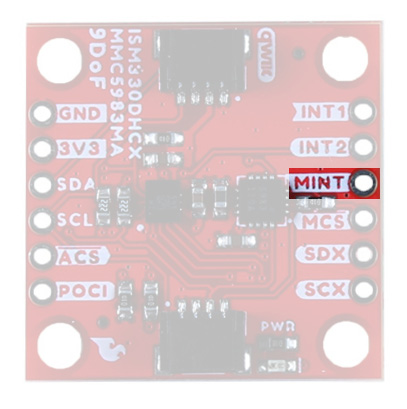
Interrupt functionality for the Magnetometer is available via the MINT pin.
Jumpers
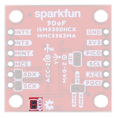
LED
If power consumption is an issue, cutting this jumper will disable the Power LED on the front of the board.
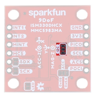
I2C
Like our other Qwiic boards, the Qwiic Micro Magnetometer comes equipped with pull-up resistors on the clock and data pins. If you are daisy-chaining multiple Qwiic devices, you will want to cut this jumper; if multiple sensors are connected to the bus with the pull-up resistors enabled, the parallel equivalent resistance will create too strong of a pull-up for the bus to operate correctly. As a general rule of thumb, disable all but one pair of pull-up resistors if multiple devices are connected to the bus. To disable the pull up resistors, use an X-acto knife to cut the joint between the two jumper pads highlighted here.
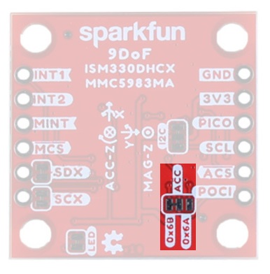
I2C Address/SPI
By default, I2C is enabled with an address of 0x6B. By manipulating this jumper, you can change the I2C address to 0x6A (cut the power side and close the ground side) or switch to SPI mode (both jumpers open).
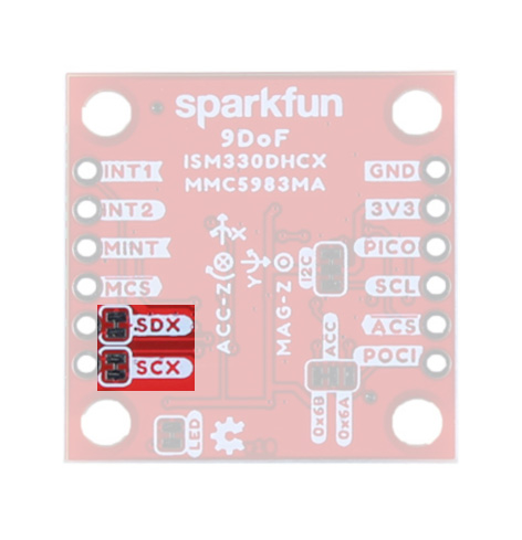
SCX/SDX
The SCX and SDX pins are specific to Mode 2 of the ISM330DHCX and are used for peripheral communication. By default they are closed - to use Mode 2 you will need to cut both traces to open the jumper.
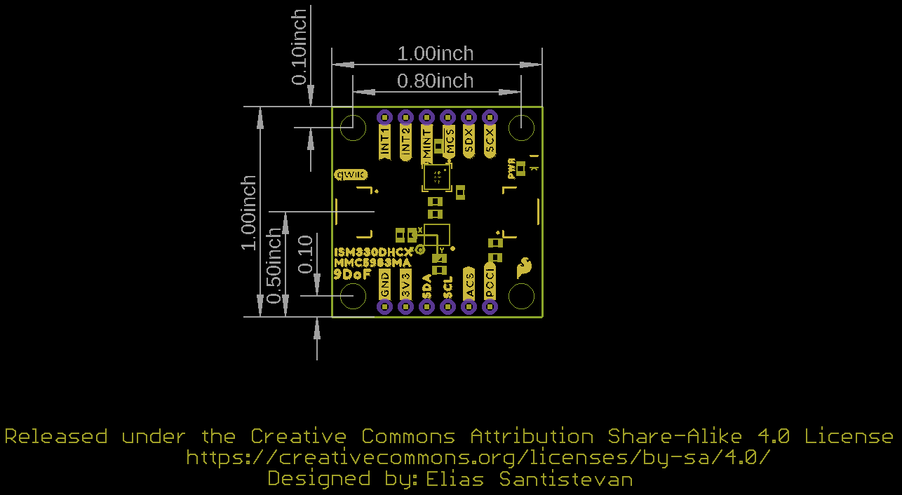
Board Outline
Like many of our Qwiic Breakout Boards, the Qwiic 9DoF ISM330DHCX-MMC5983MA measures 1" x 1".
->  <-
<-
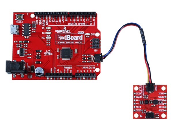
Hardware Hookup
With the Qwiic connector system, assembling the hardware is simple. All you need to do is connect your SparkFun Qwiic 9DoF - ISM330DHCX,MMC5983MA to the RedBoard Qwiic with a Qwiic cable. Otherwise, you can use the I2C pins of your microcontroller; just be aware of logic levels.
Software Setup and Programming
If this is your first time using Arduino, please review our tutorial on installing the Arduino IDE. If you have not previously installed an Arduino library, please check out our installation guide.
Both the ICM330DHCX and the MMC5983MA have independent libraries available. You can install either of these libraries through the Arduino Library Manager tool by searching for "SparkFun MMC5983MA" or "SparkFun ISM330DHCX". Users who prefer to manually install can get the libraries from either the GitHub Repositories here:
or by download the ZIP files by clicking one of the buttons below:
Examples
The ISM330DHCX and the MMC5983MA each have their own Qwiic Breakout Boards - the SparkFun 6DoF IMU Breakout - ISM330DHCX (Qwiic) or its Micro Version SparkFun Micro 6DoF IMU - ISM330DHCX (Qwiic) and the SparkFun Micro Magnetometer - MMC5983MA (Qwiic) along with corresponding hookup guides and examples.
See the linked tutorials listed below for examples:
 |
 |
| Qwiic 6DoF - ISM330DHCX Hookup Guide Examples | Qwiic Micro Magnetometer - MMC5983MA Hookup Guide Examples |
Troubleshooting
If your product is not working as you expected or you need technical assistance or information, head on over to the SparkFun Technical Assistance page for some initial troubleshooting.
If you don't find what you need there, the SparkFun Forums are a great place to find and ask for help. If this is your first visit, you'll need to create a Forum Account to search product forums and post questions.
Resources and Going Further
Now that you've successfully got your Qwiic 9DoF up and running, it's time to incorporate it into your own project!
For more information, check out the resources below:
- Schematic
- Eagle Files
- Board Dimensions
- Datasheets
- Arduino Libraries
- GitHub Hardware Rrep
Need some inspiration for your next project? Check out some of these related tutorials: