Qwiic Micro Magnetometer - MMC5983MA Hookup Guide
Introduction
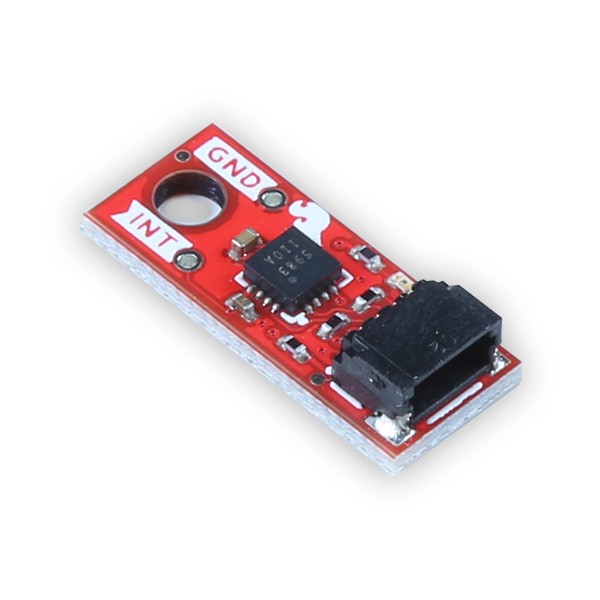
The SparkFun Qwiic Micro MMC5983MA Magnetometer is a micro-sized, 0.75in. by 0.30in. sensor that utilizes the highly sensitive triple-axis magnetometer by MEMSIC. We've attached the magnetometer IC onto an incredibly small Qwiic board form factor that we like to call Qwiic Micro! The MMC5983MA is capable of sensing down to 0.4mG, enabling a heading accuracy of ±0.5°. The Qwiic MMC5983MA IMU communicates over I2C by default utilizing our handy Qwiic Connect System, so no soldering is required to connect it to the rest of your boards.
Saturation is a problem for all mag sensors. The MMC5983MA has built-in degaussing circuitry to clear any residual magnetization. Output rates of 1000Hz, ±8G FSR, and 18-bit resolution make the MMC5983MA a phenomenal magnetic sensor for electronic compass applications.
Required Materials
To follow along with this tutorial, you will need the following materials. You may not need everything though depending on what you have. Add it to your cart, read through the guide, and adjust the cart as necessary.
Suggested Reading
If you aren’t familiar with the following concepts, we recommend checking out these tutorials before continuing.
Logic Levels
Accelerometer Basics
I2C
Serial Terminal Basics
Hardware Overview
The beautiful thing about this Qwiic board is that it is extremely simple. Let's dive in and have a look at its features!
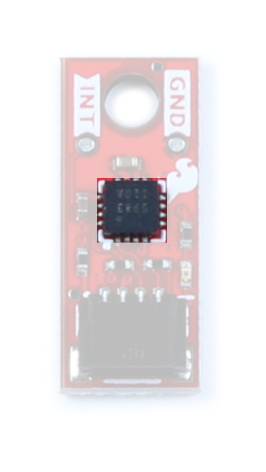
MMC5983MA
The MMC5983MA is an AEC-Q100 qualified, fully integrated 3-axis magnetic sensor with on-chip signal processing and integrated I2C/SPI bus. It has superior dynamic range and accuracy with ±8G FSR, 18bit operation, 0.4mG total RMS noise, and can enable heading accuracy of 0.5º. More information can be found in the datasheet.
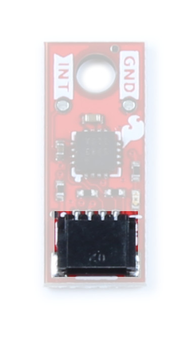
Qwiic Connector
Our Qwiic Ecosystem makes sensors pretty much plug and play. There's a Qwiic connector on the side of the Qwiic Micro Magnetometer to provide power and I2C connectivity simultaneously. The default I2C address is 0x30.
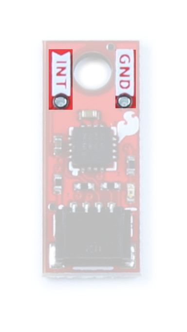
Pins
We've broken out the interrupt and ground pins to PTH on either side of the board. The interrupt pin is active high - writing “1” will enable the interrupt for completed measurements. Once a measurement is finished, either magnetic field or temperature, an interrupt will be sent to the host.
Jumpers
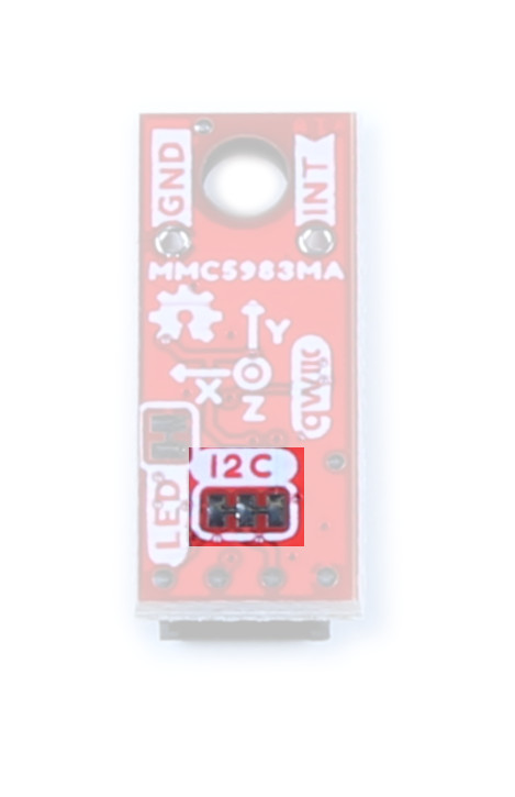
I2C
Like our other Qwiic boards, the Qwiic Micro Magnetometer comes equipped with pull-up resistors on the clock and data pins. If you are daisy-chaining multiple Qwiic devices, you will want to cut this jumper; if multiple sensors are connected to the bus with the pull-up resistors enabled, the parallel equivalent resistance will create too strong of a pull-up for the bus to operate correctly. As a general rule of thumb, disable all but one pair of pull-up resistors if multiple devices are connected to the bus. To disable the pull up resistors, use an X-acto knife to cut the joint between the two jumper pads highlighted here.
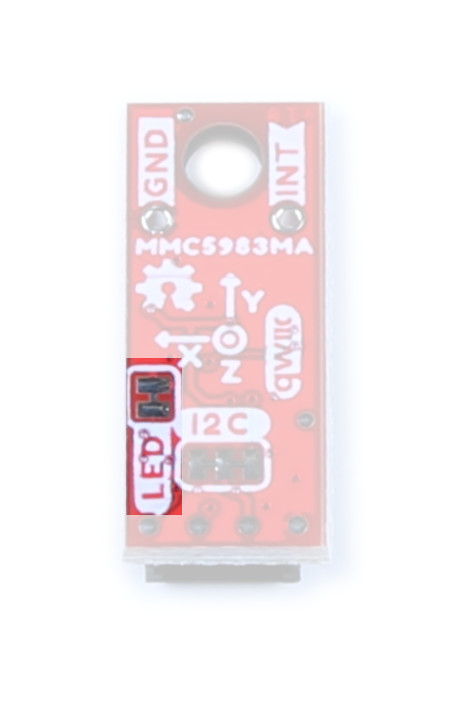
LED
If power consumption is an issue, cutting this jumper will disable the Power LED on the front of the board.
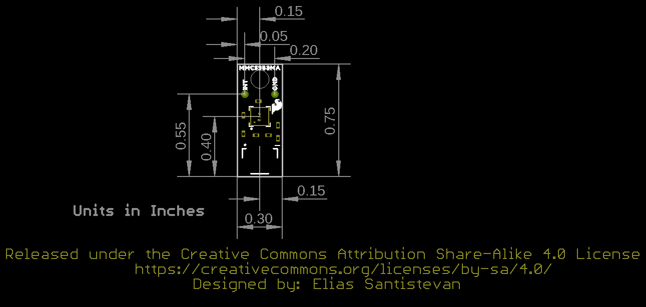
Board Outline
This ultra tiny Qwiic breakout board measures 0.75" x 0.30".

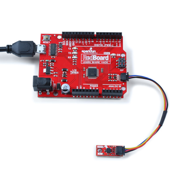
Hardware Hookup
Grab your Qwiic cable and plug one end into the RedBoard Qwiic and the other end into the Qwiic Micro Magnetometer. Voila!
Software Setup and Programming
If this is your first time using Arduino, please review our tutorial on installing the Arduino IDE. If you have not previously installed an Arduino library, please check out our installation guide.
We've written a simple Arduino library to quickly get started reading data from the Qwiic Micro Magnetometer. Install the library through the Arduino Library Manager tool by searching for "SparkFun MMC5983MA". Users who prefer to manually install it can get the library from the GitHub Repository or download the ZIP by clicking the button below:
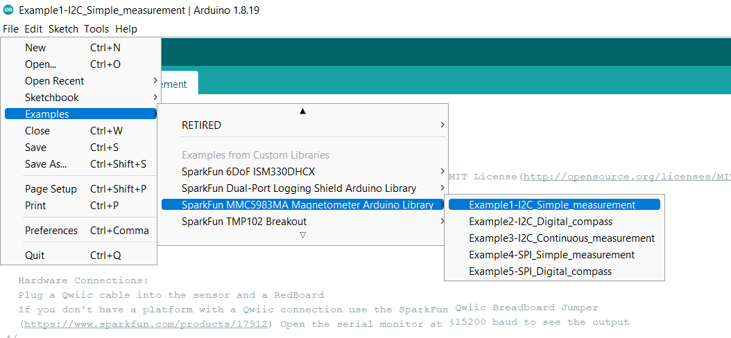
Example 1: I2C Simple Measurement
Now that we've got our library installed and our hardware all hooked up, let's look at some examples.
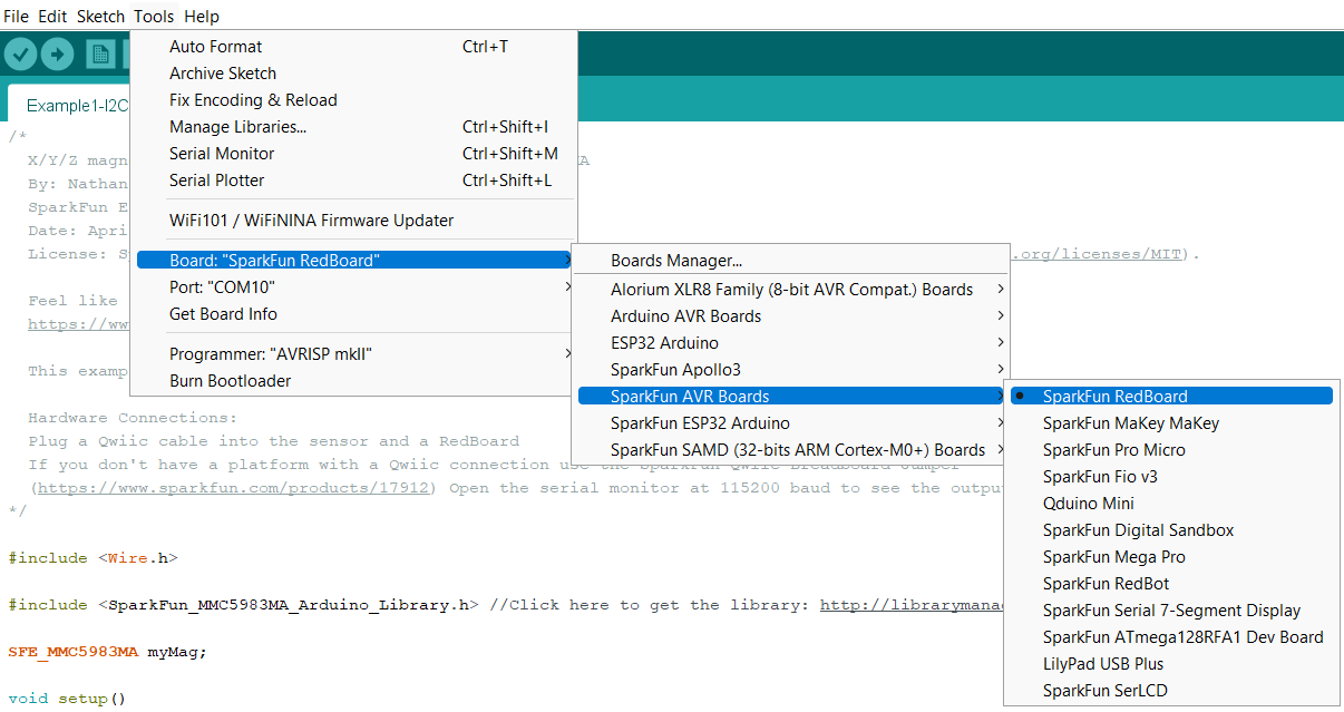
This first example just does some basic measurements. To find Example 1, go to File -> Examples -> SparkFun MMC5983MA Magnetometer Arduino Library -> Example1-I2C_Simple_measurement.
Make sure you have the correct board and port selected. For this tutorial, your selections should look something like this:
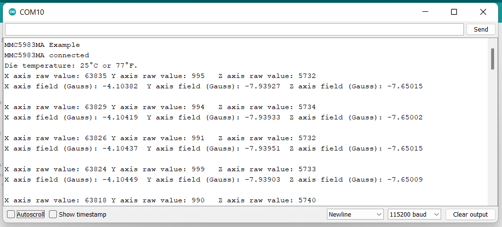
Once you're ready to go, go ahead and hit the upload button (the right facing arrow button under the "Edit" menu item). Once your code is uploaded, open the Serial Monitor and you'll see X, Y, and Z values start printing out.
Example 2: I2C Digital Compass
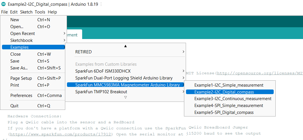
Example 2 shows how to compute the heading based on the basic X/Y/Z readings from the sensor over Qwiic. To find this example, go to File -> Examples -> SparkFun MMC5983MA Magnetometer Arduino Library -> Example2-I2C_Digital_compass.
Make sure you have the correct board and port selected. For this tutorial, your selections should look something like this:
Once you're ready to go, go ahead and hit the upload button (the right facing arrow button under the "Edit" menu item). Once your code is uploaded, open the Serial Monitor and you'll see compass readings start printing out.
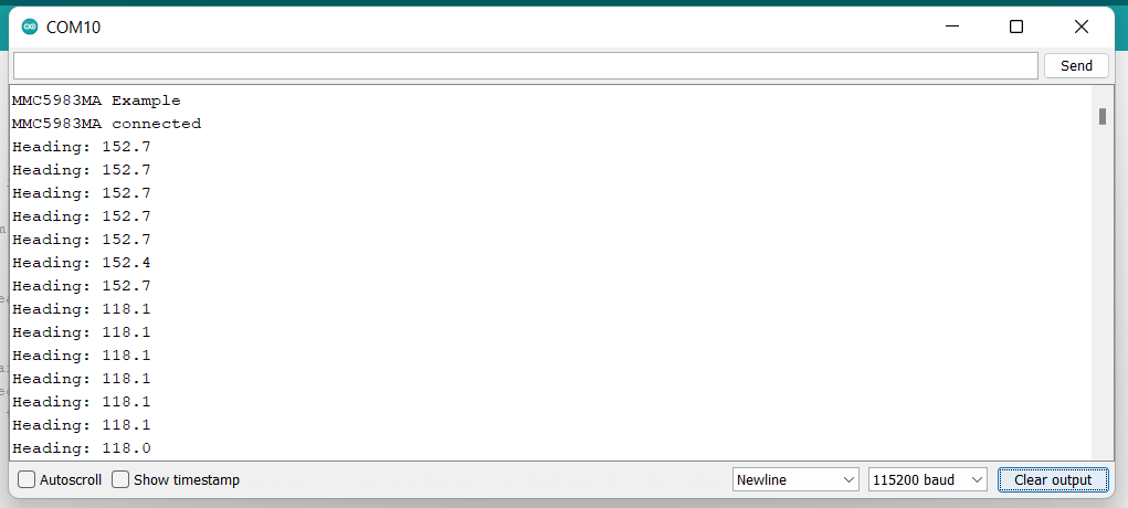
If you look at the above image, you'll see where I abruptly changed the direction the sensor was pointing.
Example 3: I2C Continuous Measurement
Example 3 demonstrates how to use interrupts to quickly read the sensor instead of polling. To find this example, go to File -> Examples -> SparkFun MMC5983MA Magnetometer Arduino Library -> Example3-I2C_Continuous_measurement.
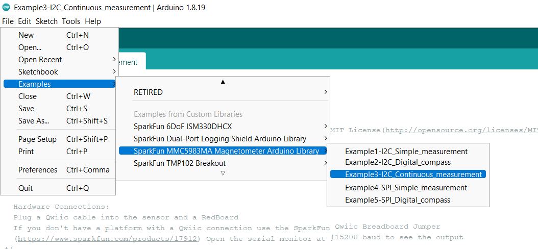
Make sure you have the correct board and port selected. For this tutorial, your selections should look something like this:
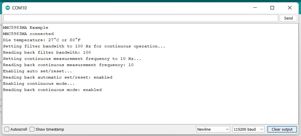
Once you're ready to go, go ahead and hit the upload button (the right facing arrow button under the "Edit" menu item). Once your code is uploaded, open the Serial Monitor and you'll see compass readings start printing out.
Examples 4 and 5
Troubleshooting
If your product is not working as you expected or you need technical assistance or information, head on over to the SparkFun Technical Assistance page for some initial troubleshooting.
If you don't find what you need there, the SparkFun Forums are a great place to find and ask for help. If this is your first visit, you'll need to create a Forum Account to search product forums and post questions.
Resources and Going Further
Now that you've successfully got your Qwiic Micro Magnetometer up and running, it's time to incorporate it into your own project!
For more information, check out the resources below:
Need some inspiration for your next project? Check out some of these related tutorials: