SparkFun WiFi IR Blaster Hookup Guide
Introduction
With the advent of WiFi-connected "smart" devices, IR remotes are quickly becoming a thing of the past. Why sort through a coffee table-full of remotes when you probably have a much smarter, WiFi-connected device device sitting conveniently in your hand?
The WiFi IR Blaster is designed to connect all of those old, legacy IR-controlled devices to a WiFi network -- exposing them to a new method of control. Want to control your TV via a web-browser? Want to ask Alexa to mute your stereo? Want to schedule triggers to your IR-controlled LED strip? These are all applications that the WiFi IR Blaster is perfect for.
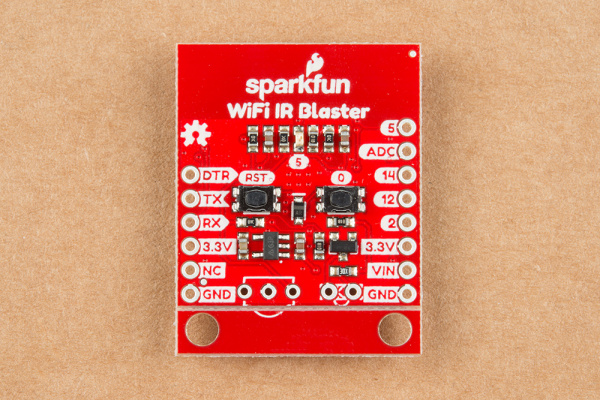
The WiFi IR Blaster combines an ESP8266 -- a powerful WiFi/microcontroller SoC -- with IR emitters and receivers. With built-in WiFi support, the ESP8266 can be programmed to provide an interface between HTTP, MQTT, TCP, etc. and infrared-controlled devices.
This tutorial will explain how to assemble the WiFi IR Blaster and it will detail how to program the ESP8266 using the Arduino IDE. Once complete, you'll have a simple web server than can emit infrared signals at the click of a browser-page.
Required Materials
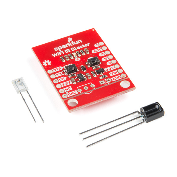
The WiFi IR Blaster includes the board, an infrared emitter and an infrared receiver. You'll need a handful of other tools and components to get it powered and programmed:
Infrared Remote Control
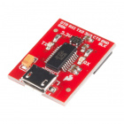
COM-14865The SparkFun Beefy 3 - FTDI Basic Breakout is primarily used to program the ESP8266, but it's also able to supply the 3.3V/300mA power required by the Blaster. Although you can use any 3.3V USB-to-serial converter, this is the one we recommend.
Headers -- either right-angle or straight are the recommended interface between your board, the programmer, a breadboard, perfboard, etc.
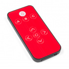
If you don't have an IR remote handy, the SparkFun IR RemoteControl is a useful tool for testing. It may even accidentally work with your TV!
In addition to those components, you'll need a soldering iron, solder, and general soldering accessories.
To add, you'll also need a local WiFi network that you can connect your ESP8266 up to. It also helps to have a second device -- smartphone or computer -- that's also connected to that network.
Suggested Reading
If you aren’t familiar with the following concepts, we recommend checking out these tutorials before continuing.
How to Solder: Through-Hole Soldering
IR Communication
IR Control Kit Hookup Guide
Hardware Overview
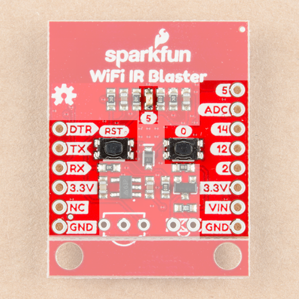
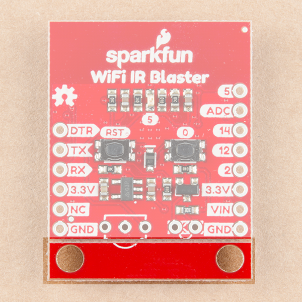
The WiFi IR Blaster is based around the ESP-12S ESP8266 module. This module equips the ESP8266 with a crystal, 4Mb flash, and PCB antenna -- just about everything it needs to get going. The antenna sits under the SparkFun logo, so try not to place anything that may interfere with WiFi signals near that area.
Supporting the ESP8266 are a reset and general purpose button, a user LED, and an array of pin breakouts.
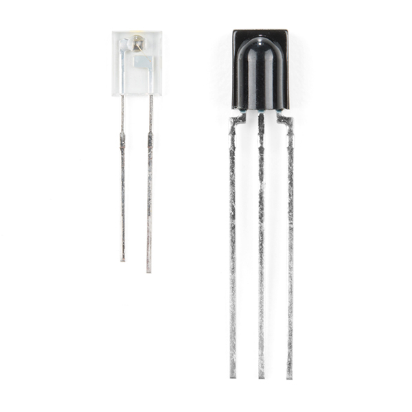
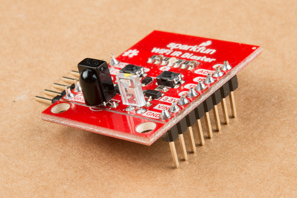
Of course, there's also the IR emitter and detector. These components are packaged with the board, but not soldered in place. This allows you to solder both components at any angle your project requires. It also leaves the option to customize the board and spec out your own emitter and/or receiver.
The IR emitter is a Lite-ON LTE-302. It's driven by an NPN transistor, which helps amplify the current through the LED.
The IR receiver is a TSOP38238. This is a simple IR receiver hard-coded to receive IR signals modulated at 38kHz.
Assembly Tips
Time to whip out a soldering iron! The IR emitter and receiver do not come soldered onto the WiFi IR Blaster. You'll also need to solder headers for programming and power supply pins.
While you have your iron out, you may also want to solder headers into the 6-pin serial header and the 8-pin power/GPIO header. Which headers you solder into the board ultimately depends on your application. I like soldering in a male right-angle header to the 6-pin header, which makes attaching the USB-to-serial board easier. Straight male headers work well for plugging the board into a bread- or perf-board.
Powering the WiFI IR Blaster
The WiFi IR Blaster includes a 3.3V low dropout regulator which can supply up to 600mA and handle voltage inputs up to 6V. To use this regulator, connect your power source to the VIN pin.
Alternatively, a pair of 3.3V pins are broken out on both headers. This pin directly supplies the ESP8266, so it should remain regulated to the range of ESP8266: 3.0V-3.6V.
⚡Powering via FTDI Header
The WiFi IR Blaster can be powered via the 3.3V pin on the 6-pin serial header. Voltage supplied to this pin should be regulated to 3.3V. Your power source will need to be able to supply at least 300mA, which most FTDI boards cannot do. We recommend the Beefy 3 FTDI Basic Breakout which can supply up to 600mA.
Removing the Standoff Edge
A pair of standoffs are provided towards the bottom of the WiFi IR Blaster. If you don't need these standoffs, and want to save some space, the standoff board can be removed by breaking it along the v-score line.
Programming the ESP8266
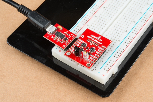
The WiFi IR Blaster's ESP8266 is designed to be programmed with a 3.3V FTDI Basic or a similar 6-pin USB-to-Serial converter. We recommend a Beefy 3 FTDI Basic Breakout if you're powering the Blaster with the FTDI (see the note in the previous section for more information).
Plug your USB-to-serial converter in making sure you match the "GND" and "DTR" signals on the edge.
Arduino Board Support
Before programming the WiFi IR Blaster's ESP8266, you'll need to install the ESP8266 Arduino board definitions. The board definitions can be found in the ESP8266 Arduino GitHub repository. For installation instructions, check out this section of the README.
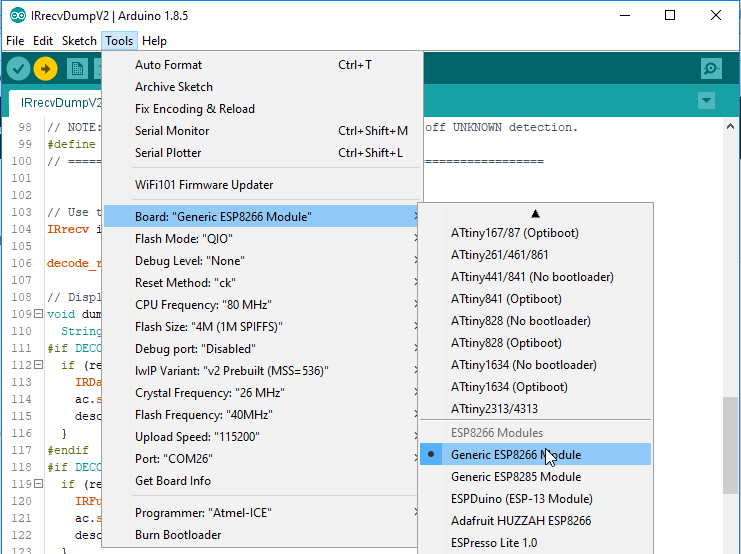
The WiFi Blaster board definition is not included with the Arduino ESP8266 board files, but it can be uploaded to as a Generic ESP8266 Module. Verify your settings look like below:
| Board: Generic ESP8266 Module | |
|---|---|
| Board | Generic ESP8266 Module |
| Flash Mode | QIO |
| Debug Level | None |
| Reset Method | ck |
| CPU Frequency | 80 MHz |
| Flash Size | 4M (1M SPIFFS) |
| Debug Port | Disabled |
| lwIP Variant | v2 Prebuilt (MSS=536) |
| Crystal Frequency | 26 MHz |
| Flash Frequency | 40MHz |
| Upload Speed | 115200 |
Auto vs. Manual Reset Into Bootloader
In addition to the RX and TX pins, the FTDI's DTR pin is used to reset the ESP8266 and get it into bootloader mode. The board includes circuitry to automatically reset and bootload the board; in most cases, you shouldn't have to do anything special to program it.
The auto-reset circuit can be a little flaky, however. If the board isn't taking a program, you may see an error like "error: espcomm_upload_mem failed".
If this shows up repeatedly, you may need to manually reset into bootloader mode be holding pin 0 low while resetting the ESP8266:
- Hold down the "0" button
- Press and release the "RST" button
- Release the "0" button
The timing of this can be a little tricky. Try resetting it into bootloader mode, then quickly uploading your sketch.
Decreasing the upload speed baud rate to something around 115200 bps can also help improve the reliability of the reset circuit.
Testing the Receiver
ESP8266 IR Remote Arduino Library
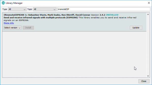
IRremoteESP8266 -- an IR Arduino library specific to the ESP8266 -- gets our recommendation for sending and receiving IR signals with this board. You can download the library from their GitHub page, or by searching out IRremoteESP8266 in your Arduino library manager.
The IR remote library includes an exhaustive collection of examples which demonstrate how to send and receive IR signals. To test out the receiver, open up the IRrecvDumpV2 example by navigating to the File > Examples > Examples from Custom Libraries > IRremoteESP8266 menu.
Before uploading the sketch, you need to modify the kRecvPin pin definition where global variables are defined.. This sets the ESP8266 pin connected to your IR receiver. Set it to 13.
language:c
uint16_t kRecvPin = 13;
Once that modification has been made, upload away! (Make sure the board is set correctly to "NodeMCU 1.0 (ESP-12E Module)".) Then open up the serial monitor and set the baud rate to 115200.
You should see a "IRrecvDumpV2 is now running and waiting for IR input on Pin 13" message print out. If you don't try tapping the board's reset button.
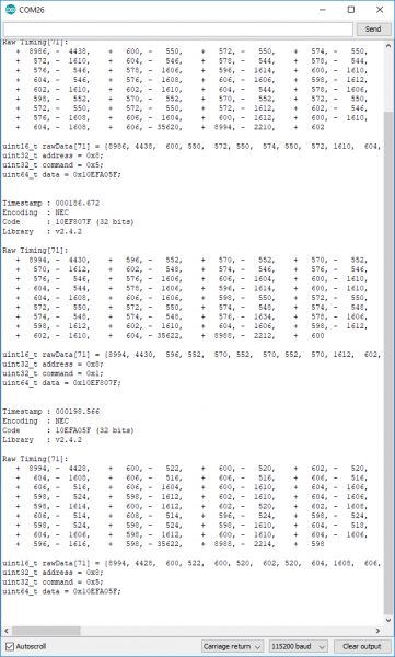
Then aim an IR remote at the board and hit a button. You should see a stream of data shoot by.
The most important bits of this output are the last 4 lines, which should look a lot like C variable declarations. For example:
uint16_t rawData[71] = {8994, 4428,  600, 522,  600, 520,  602, 520,  604, 1608,  606, 516,  606, 516,  606, 516,  606, 516,  606, 1604,  600, 1610,  604, 1606,  598, 524,  598, 1612,  602, 1610,  604, 1606,  598, 1614,  600, 1612,  602, 520,  602, 1608,  606, 514,  608, 514,  596, 524,  598, 524,  598, 524,  598, 524,  598, 1610,  604, 518,  604, 1606,  598, 1612,  600, 1610,  604, 1606,  596, 1616,  598, 35622,  8988, 2214,  598};  // NEC 10EFA05F
uint32_t address = 0x8;
uint32_t command = 0x5;
uint64_t data = 0x10EFA05F;
These lines will be used in the next example, where we test the emitter.
Sending IR Codes
Armed with the timing data for your desired IR command, load up the IRsendDemo example. Around line 42, replace the rawData array with the one you copied from the previous example. You shouldn't have to modify the pin definition for the IR emitter -- just double-check to make sure IR_LED is set to 4, which is the ESP8266 pin connected to the IR emitter.
With that change made, upload the code. Then point the IR emitter at your device. The emitter has a range of about 10 feet, so you may need to get a little close. It should receive a command every 6 seconds.
If your code is Sony- or NEC-encoded, you can also plug the value from data in the previous example to send an NEC or Sony command. This is quite a bit more efficient than sending the raw timing data.
Sending NEC Codes via Web Server
One last example which really begins to show the power of this module is the IRServer example. This sketch will connect your ESP8266 to WiFi and set it up as a web server. When the right HTTP endpoint is hit, it will send a desired command. So you can trigger your device from a web browser!
This example requires that you have an NEC-encoded signal to send.
Before uploading this example, plug your WiFi network's SSID and password into the ssid and password variables.
Then adjust some of the static HTML in the handleRoot() function to send your desired code. This is a little tricky. You need to find your NEC code from the receive example -- in my case it was 0x10EFA05F. You'll also need to convert this value to decimal (here's a calculator for that). In my case it was 284139615. Plug those two values into a new line of C-string'ed HTML. I added this line on line 59, for example:
language:c
              "<p><a href=\"ir?code=284139615\">Send 0x10EFA05F</a></p>" \
Then upload the code! Open the serial monitor to check on your ESP8266's connection status. Once connected it should provide you an IP address.
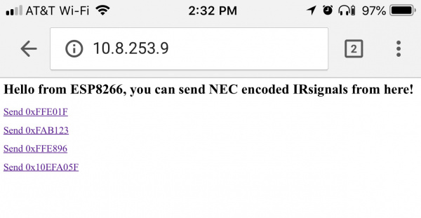
On a device connected to the same WiFi network, plug that IP address into the address bar. You should be greeted with a page like this:
Then aim your IR Blaster at a device, and click your newly added link. Your signal should be routed from your phone or computer, over the WiFi airwaves, to the device you want to control.
IR Controller Firmware
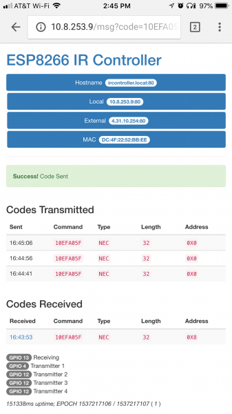
Exploring the IRRemoteESP8266 library is just the very tip of this WiFi IR Blaster iceberg. We highly recommend checking out the IR Controller ESP8266 firmware. This fully featured firmware combines IR send and receive functions with a web server. It monitors for received commands, and provides a handy interface to emit those back out with the ESP8266. There are even instructions for connecting the Blaster to an Alexa service.
If you give this firmware a spin, just remember you'll need to specify the IR emitter and receiver pins. This is what I've set the pins variables to:
language:c
const int pinr1 = 13;                               // Receiving pin
const int pins1 = 4;                                // Transmitting preset 1
const int pins2 = 12;                               // Transmitting preset 2 (not used)
const int pins3 = 12;                               // Transmitting preset 3 (not used)
const int pins4 = 12;                               // Transmitting preset 4 (not used)
const int configpin = 5;                            // Reset Pin

// User settings are above here
const int ledpin = 0;                               // Built in LED defined for WEMOS people
You'll also need to install a handful of libraries, which are all described in the Setup section of the README.
With those few modifications, you should be up-and-IR-controlling in no time!
Resources and Going Further
Need more information on the WiFi IR Blaster? Checkout our GitHub repository and the rest of these documents:
- GitHub Product Repository -- GitHub repository where you can find all of our latest hardware and software design files.
- Hardware
- Schematic -- PDF schematic
- Eagle Files -- PCB design files
- ESP-12S Datasheet -- ESP8266 module w/ integrated crystal, antenna, flash
- LTE-302 Datasheet -- IR emitter
- TSOP382 Datasheet -- IR receiver
- Firmware
- IRremoteESP8266 Arduino Library -- ESP8266 IR Arduino library
- ESP8266 IR Controller Firmware -- Full-featured ESP8266 IR controller firmware
- SFE Product Showcase
Want more information or inspiration? Check out the following links!
