MicroPython Programming Tutorial: Getting Started with the ESP32 Thing
 Shawn Hymel
Introduction
In this guide, we will walk through the process of setting up MicroPython on the ESP32 Thing and writing some example programs. Each "experiment" will show you how to wire up an example circuit and then control it using MicroPython.
What is MicroPython?
MicroPython is a lean implementation of the Python 3 programming language that has been pared down to run efficiently on microcontrollers. Python is a relatively simple (but powerful) language that is easy for beginners to pick up and has been gaining popularity in schools as an introductory language. MicroPython has nearly all of the features of Python, which means that interacting with hardware is now easily accessible to beginners and seasoned Python programmers alike.
Why the ESP32 Thing?
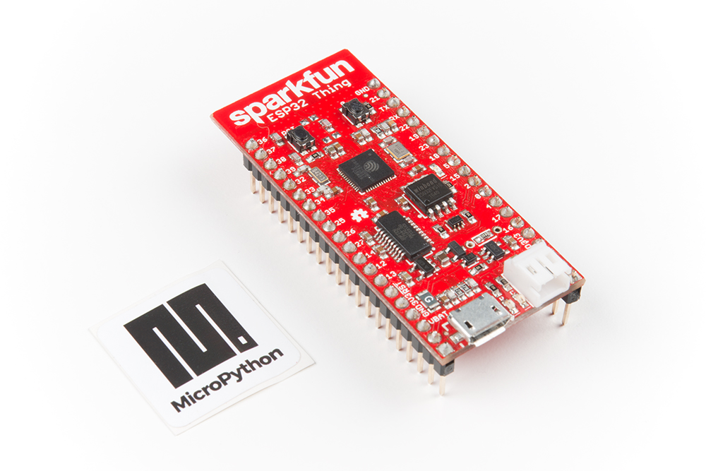
MicroPython is supported on many different microcontroller platforms, and more are being added all the time. The ESP32 is a great tool for learning MicroPython, as it has a powerful controller (240 MHz) with lots of RAM (520 kB). Additionally, the ESP32 has a built-in WiFi module, which makes networking and connecting to the Internet quite easy. All this is packaged up into a development board for you on SparkFun's ESP32 Thing.
Required Materials
To work through the activities in this tutorial, you will need a few pieces of hardware:
Suggested Reading
If you aren't familiar with the following concepts, we recommend checking out these tutorials before continuing:
What is a Circuit?
Voltage, Current, Resistance, and Ohm's Law
How to Use a Breadboard
ESP32 Thing Hookup Guide
Hardware Overview
ESP32 Thing Pinout
The ESP32 has a number of features, such as:
- 18 analog-to-digital converter (ADC) channels
- 3 SPI interfaces
- 3 UART interfaces
- 2 I2C interfaces
- 16 PWM outputs
- 2 digital-to-analog converters (DAC)
- 2 I2S interfaces
One I2C, two of the UART interfaces, and one of the SPI interfaces can be assigned to any pin your project requires. However, there are a few hardware features (namely the ADC and DAC) that are assigned static pins. The graphical reference below helps demonstrate where you can find those peripherals.
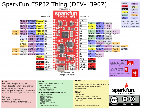
Input Only Pins: 34-39
Pins 34, 35, 36, 37, 38 and 39 cannot be configured as outputs, but they can be used as either digital inputs, analog inputs, or for other unique purposes. Also note that they do not have internal pull-up or pull-down resistors, like the other I/O pins.
GPIO pins 36-39 are an integral part of the ultra low noise pre-amplifier for the ADC – they are wired up to 270pF capacitors, which help to configure the sampling time and noise of the pre-amp.
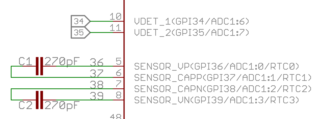
From the ESP32 Thing Schematic: GPIO 36-39 are tied together with caps. Those and pins 34 and 35 are input only!
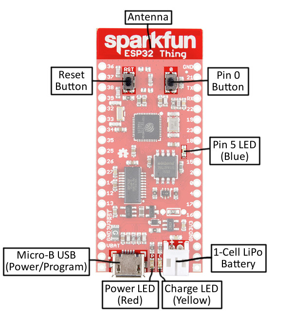
ESP32 Thing Board Overview
The ESP32 Thing breaks out most of the pins on the ESP32 chip and gives you access to a few extra features, such as a LiPo battery charger, 4 MB of flash memory, an FTDI USB-to-Serial chip, and a user-controlled LED and button.
Powering the ESP32 Thing
The easiest ways to power the ESP32 Thing is through either the onboard USB connector or through the single-cell LiPo battery connector. Note that if a battery and USB are connected at the same time, the USB connection will charge the LiPo at a rate up to 500 mA.
⚡ The ESP32's operating voltage range is 2.2 to 3.6V. Under normal operation the ESP32 Thing will power the chip at 3.3V. The I/O pins are not 5V-tolerant! If you interface the board with 5V (or higher) components, you'll need to do some level shifting.
The 3.3V regulator on the ESP32 Thing can reliably supply up to 600mA, which should be more than enough overhead for most projects. The ESP32 can pull as much as 250mA during RF transmissions, but we've generally measured it to consume around 150mA, even while actively transmitting over WiFi. The output of the regulator is also broken out to the sides of the board (the pins labeled 3V3). These power pins can be used to supply external components.
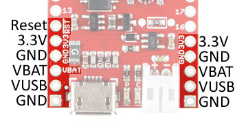
In addition to USB and battery connectors, the VBAT, and VUSB pins are all broken out to both sides of the board. These pins can be used as an alternative supply input to the ESP32 Thing. The maximum, allowable voltage input to VUSB is 6V, and VBAT should not be connected to anything other than a single-cell LiPo battery. Alternatively, if you have a regulated voltage source between 2.2V and 3.6V, the "3V3" lines can be used to directly supply the ESP32 and its peripherals.
Setup
Serial Terminal Program
To communicate with the Read–Eval–Print Loop (REPL) running on the ESP32, you will need to install a serial terminal program for your particular operating system (OS). The following tutorial makes several good recommendations as to which programs to use for the 3 major operating systems:
Serial Terminal Basics
Text Editor
At the time of this writing, no major integrated development environments (IDEs) support MicroPython for the ESP32 (for example, Mu was developed for MicroPython but does not support the ESP32). As a result, you will need to write code in a raw text editor and then save the files as somename.py. Some recommended text editors that work well for writing code include:
- Atom
- Windows, Mac, Linux
- Free (maintained by GitHub)
- Brackets
- Windows, Mac, Linux
- Free (owned by Adobe)
- Sublime Text
- Windows, Mac, Linux
- Paid version with free trail
- Notepad++
- Windows
- Free
- TextWrangler
- Mac
- Free
- Emacs
- Linux
- Free
Load MicroPython on the ESP32 Thing
Unfortunately, the ESP32 Thing does not come ready to run MicroPython programs out of the box. To run MicroPython on the ESP32, you will need to first load the interpreter on it. To do that, follow the steps outlined in the How to Load MicroPython on a Microcontroller Board (specifically, the steps found in the ESP32 Thing section).
How to Load MicroPython on a Microcontroller Board
Install Python on Your Computer
In order to upload MicroPython programs to the ESP32, we will use a tool called ampy, which is a Python script that can read and write files to a MicroPython board over a serial connection. Because ampy is a Python script that runs on a host computer, we will need to install Python.
Instructions for installing Python can be found at python.org. Download and run the installer for your OS, or use your OS's package manager to install Python (if you are on Linux). Ampy will run with Python 2 or Python 3, so choose whichever version you like (we recommend Python 3, as MicroPython is based on Python 3, so the language will be similar).
If you are installing on Windows, make sure the "Add Python <x.x> to PATH" checkbox is selected.
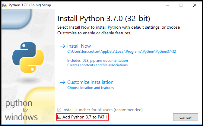
For more information on using Python on windows, see this link.
Install ampy
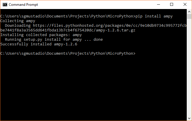
Once you have installed Python, open a terminal for your host computer, and enter the following command:
language:shell
pip install adafruit-ampy
You should see a printout showing that ampy was downloaded and installed.
REPL (Hello, World!)
One of the easiest ways to interact with MicroPython running on the ESP32 is to enter commands via the REPL over a serial connection. This can be extremely helpful if you want to test out various parts of code before writing them down in a (slightly more permanent) text document that is then uploaded to the ESP32.
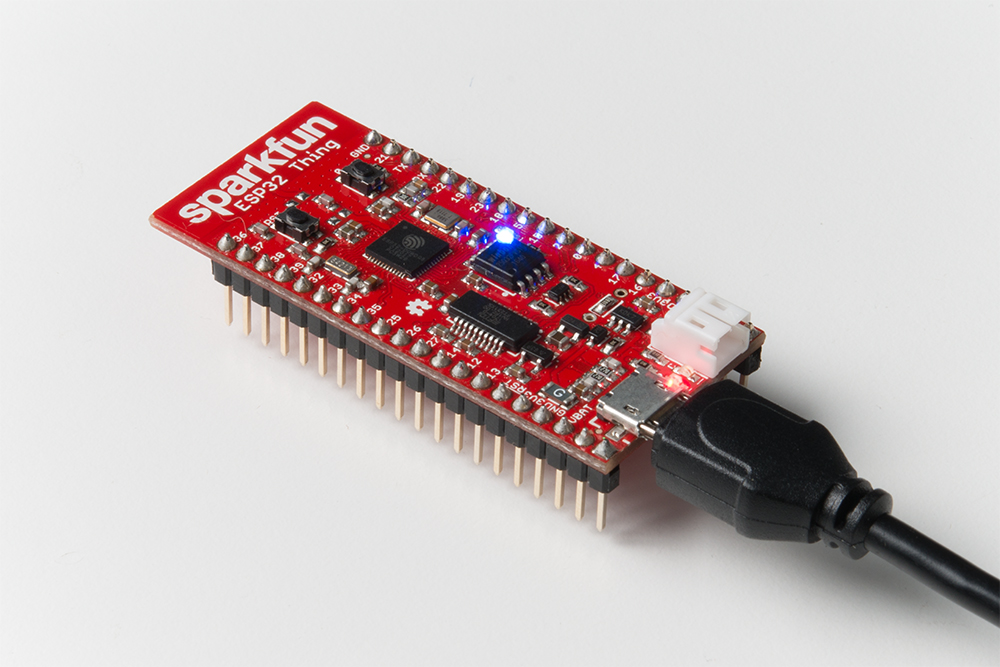
To start, connect the ESP32 Thing to your computer using a USB micro-B cable. If you are on Windows, open the Device Manager and find out which COM port your ESP32 Thing is associated with (for example, COM7). On macOS, it will likely be /dev/cu.usbserial-<some letters/numbers>, and on Linux, it’s probably something like /dev/ttyUSB0.
Open your Serial Terminal program of choice and connect to the ESP32 using the following connection details:
- Speed: 115200 bits per second
- Data Bits: 8
- Parity: None
- Stop Bits: 1
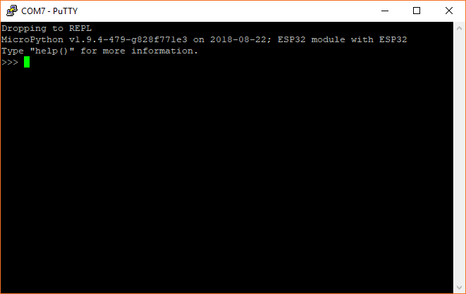
Once you have a connection, press enter once to get a REPL command prompt (>>>).
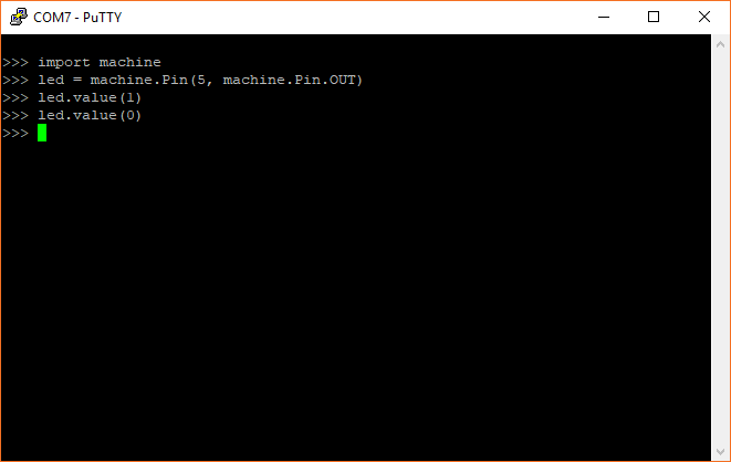
When you see that command prompt, enter the following commands one at a time:
language:shell
import machine
led = machine.Pin(5, machine.Pin.OUT)
led.value(1)
This should turn on the LED found on the ESP32 Thing (the blue LED located by pin 5).
Type the following command to turn it off:
language:shell
led.value(0)
Code to Note
The first thing we typed was import machine. machine is the MicroPython module that gives us control of the various general purpose input/output (GPIO) pins and special functions, such as I2C and interrupts. We use the keyword import to make all of the functions in the machine module available for us to use.
We then create a machine.Pin object and store it in the label led. When defining a machine.Pin object, we supply a number of arguments, including which pin number we want to use (the pin numbers can be found in white numbers on the side of the ESP32 Thing) and how we want to use that pin (e.g. as an input or output).
Because we set the pin as an output (as given by machine.Pin.OUT), we can drive the pin to logic low (0 V) or logic high (3.3 V) by setting its value to 0 (logic low) or 1 (logic high). To drive the pin high, we write led.value(1). This has the effect of turning on the LED.
Similarly, we can turn the LED off with led.value(0), which sets the pin to 0 V.
Experiment 1: Digital Input and Output
In the REPL section, we saw how to control an LED by individually calling commands in the REPL. This time, we are going to show two examples: how to respond to a button press and how to blink the onboard LED by writing code in a text editor and uploading that file to the ESP32.
There is one minor problem with MicroPython on the ESP32 that we will address in this experiment: if your code includes a forever loop, the MicroPython interpreter will continue to run your code (forever!), which means we never get a REPL prompt. The only way to stop a forever loop like this is to open a serial connection to the ESP32 and send it a ctrl + c command to terminate the running program.
The ampy tool requires REPL to upload new programs, so if the ESP32 is stuck running one of our programs, you will not be able to upload a new program. In the following experiment, we will build a tool that allows us to press the ESP32 Thing's onboard button (labeled 0 on the board) to stop our program and return to REPL.
Hardware Connections
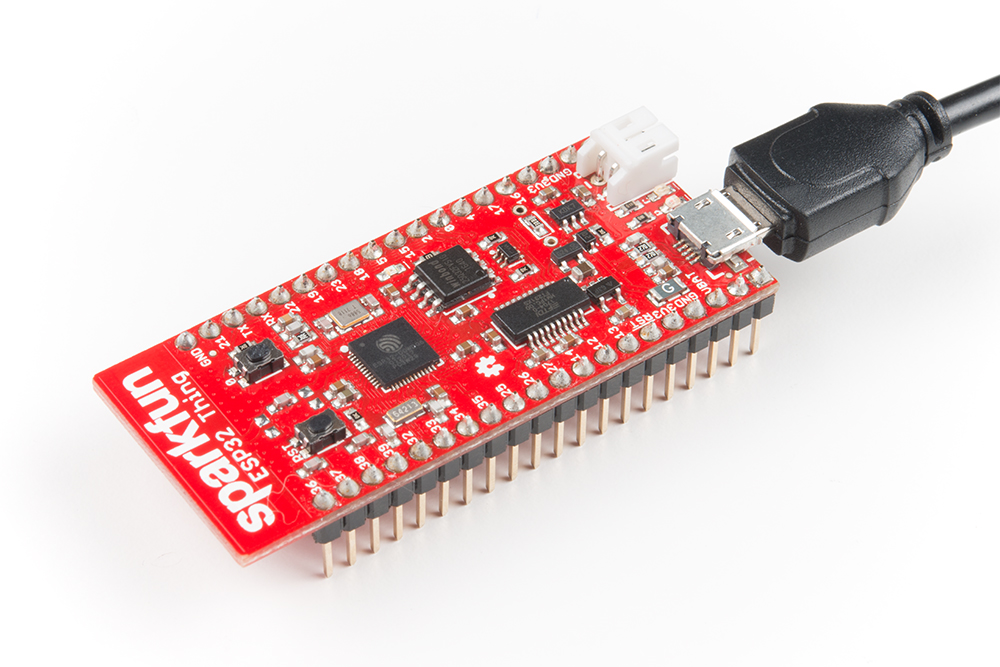
Good news! We can do this experiment with just the ESP32 Thing board by itself.
Code Part 1: Push Button, Get REPL
In your text editor of choice, enter the following code:
language:python
import machine
import sys
import utime

# Pin definitions
repl_button = machine.Pin(0, machine.Pin.IN, machine.Pin.PULL_UP)

# Wait for button 0 to be pressed, and then exit
while True:

    # If button 0 is pressed, drop to REPL
    if repl_button.value() == 0:
        print("Dropping to REPL")
        sys.exit()

    # Do nothing
    utime.sleep_ms(1)
Save the code with a name like button.py.
Run It:
To upload the program to the ESP32, we first need to rename it to main.py. In most configurations of MicroPython, you will find two files stored on the microcontroller: boot.py and main.py. As soon as the microcontroller receives power (or directly after a reset), the code in boot.py will be run. Then, main.py will run. Note that once main.py finished executing, it will be run again (over and over again forever).
In essence, main.py acts as a forever loop for our code. However, rather than trying to deal with uploading 2 files to the ESP32, we are just going to worry about putting our code in main.py and uploading that.
Open a command terminal on your host computer (not a serial terminal!). Navigate to wherever you stored your button.py file. For example (on Windows):
language:shell
cd Documents\Projects\Python\MicroPython
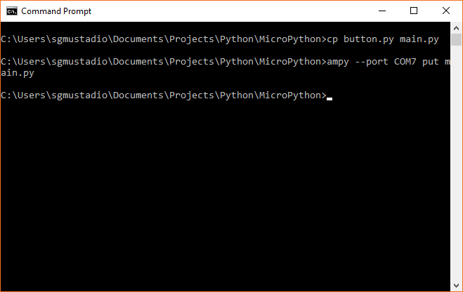
Then, enter the following two commands to create a copy of your code named main.py and upload it to the ESP32 (change <PORT> to the serial port of your ESP32, such as COM7 for Windows, /dev/cu.usbserial-<some letters/numbers> for macOS, or /dev/ttyUSB0 for Linux):
language:shell
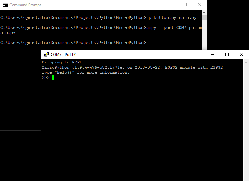
cp button.py main.py
ampy --port <PORT> put main.py
If you are on Windows and your port number is higher than 10, ampy may give you an error message like so: ampy.pyboard.PyboardError: failed to access \\.\COM24. There is a known issue with Python's recognition of Windows ports above 10, but ampy does not take this into account, so we must format our port explicity for Python. Try formatting your COM port as you see it here (replacing <PORT> with your port number/location): \\.\<PORT>
ampy.pyboard.PyboardError: failed to access \\.\COM24. There is a known issue with Python's recognition of Windows ports above 10, but ampy does not take this into account, so we must format our port explicity for Python. Try formatting your COM port as you see it here (replacing <PORT> with your port number/location): \\.\<PORT>If the file was uploaded, you should not see any error messages from ampy. If you do see some error messages, check out the Troubleshooting section for some tips.
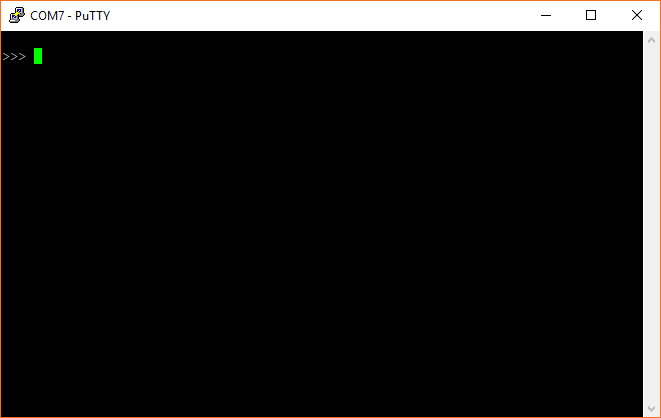
After uploading your code, it should automatically start running. However, because our code simply exits on a button push, there is nothing to see here. Open a serial terminal and create a connection to your ESP32 Thing. You should see a blank terminal window, and even if you try typing some characters, nothing should appear.
Press the 0 button on your ESP32 Thing board.
As soon as you do, you should see a message appear in your serial terminal saying "Dropping to REPL" followed by the MicroPython version number and a command prompt (>>>). Note that we are using two separate programs here: the command terminal to upload the program and the serial terminal (I'm using PuTTY for my serial terminal) to communicate with REPL.
Code to Note:
Our program is relatively simple. We first import the machine, sys, and utime modules. machine allows us to control connected hardware, like pins. sys gives us access to underlying interpreter values and the ability to exit out of our forever loop in main.py. Finally, utime allows us to get the local machine time (assuming we have a connected real-time clock) or tell our program to wait for a specified amount of time.
Much like in our REPL example, we create a machine.Pin object for pin 0, but we make it an input this time. We supply a third argument: machine.Pin.PULL_UP. This says that we want to enable the ESP32's internal pull-up resistor for pin 0. This allows the voltage on pin 0 to stay at 3.3 V until we push the onboard button, which subsequently pulls the voltage on the pin down to 0 V. We can use this technique to determine if the button has been pressed.
Everything indented under while True: runs forever. Each line is executed sequentially before returning to the top of the while loop.
Within the loop, we check to see if the button has been pressed:
language:python
if repl_button.value() == 0:
    print("Dropping to REPL")
    sys.exit()
If it has, we print a message out to the serial terminal and then call sys.exit(), which raises a SystemExit exception. This will force the program to exit (and the MicroPython interpreter will perform any garbage collection or cleanup as necessary).
If no button push is detected, we tell the ESP32 to do nothing (sleep) for 1 ms:
language:python
utime.sleep_ms(1)
This process is repeated again within the while loop. In future examples, we will continue using this "drop to REPL" button method to help us upload new code.
Code Part 2: Blinky
In a text editor, enter the following code:
language:python
import machine
import sys
import utime

# Pin definitions
repl_button = machine.Pin(0, machine.Pin.IN, machine.Pin.PULL_UP)
led = machine.Pin(5, machine.Pin.OUT)

# Blink forever
while True:

    # If button 0 is pressed, drop to REPL
    if repl_button.value() == 0:
        print("Dropping to REPL")
        sys.exit()

    # Turn LED on and then off
    led.value(1)
    utime.sleep_ms(500)
    led.value(0)
    utime.sleep_ms(500)
Save the code with a name like blink.py
Run It:
Before uploading our code, we need to first stop our first program. Close out of the serial terminal (this is important to free up the serial port) and press button 0 on your ESP32 Thing (this is also important!). Remember: pressing button 0 stops our program and gives us a REPL prompt. ampy will need this to upload a new program.
In a command terminal, copy blink.py and rename it as main.py (don't worry about overwriting your previous main.py, as we have the first example code saved as button.py). Don't forget to change <PORT> to your particular port number/location.
language:shell
cp blink.py main.py
ampy --port <PORT> put main.py
The onboard blue LED should begin blinking on and off every second.
Open up a serial terminal and connect to your ESP32 Thing. Press and hold button 0 until the blinking LED stops. You should also see a REPL prompt appear.
Code to Note:
This time, we combined parts from our first REPL example and our button example. We added the following part in the while loop:
language:python
led.value(1)
utime.sleep_ms(500)
led.value(0)
utime.sleep_ms(500)
Much like we saw in the REPL example, we turn the LED on with led.value(1) and turn it off with led.value(0). We sleep 500 ms between each action so that we can see the LED blinking.
At the top of our while loop, we added our "drop to REPL" button press code to make debugging and uploading code on the ESP32 easier. Note that you need to hold down button 0 this time, as it can take over 1 second for one iteration of the while loop to complete. Execution needs to return to the beginning of the loop before checking for a button 0 press again.
Experiment 2: Pulse Width Modulation (PWM)
Pulse width modulation is the technique of switching a digital signal on and off very quickly to control a variety of electrical components. By varying the amount of time a signal is on vs. off, you can vary the amount of electrical power provided to a component. We can use this, for example, to dim an LED or control the speed of a motor. To learn more about PWM, see this tutorial.
In this example, we are going to create a simple LED animation that occurs as long as a button is held down.
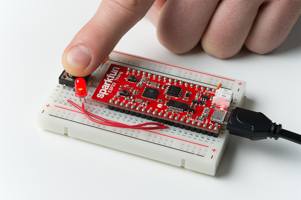
Hardware Connections
Connect an LED and a button to the ESP32 as per the following diagram:
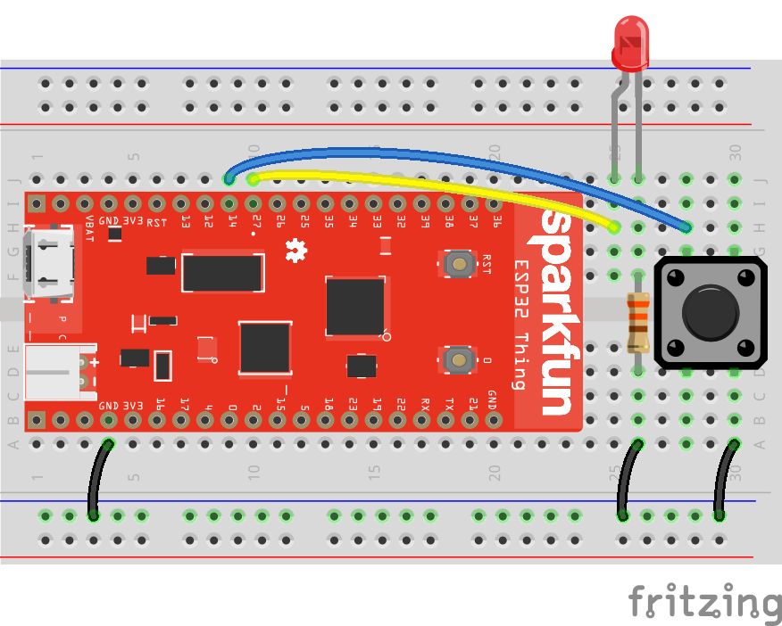
Code: LED Animation
In a new file, enter the following code:
language:python
import machine
import sys
import utime

# Pin definitions
repl_button = machine.Pin(0, machine.Pin.IN, machine.Pin.PULL_UP)
repl_led = machine.Pin(5, machine.Pin.OUT)
button = machine.Pin(14, machine.Pin.IN, machine.Pin.PULL_UP)
pwm_pin = machine.Pin(27, machine.Pin.OUT)

# Create a PWM object out of our pin object
pwm = machine.PWM(pwm_pin)

# Slowly fade LED brightness
while True:

    # If button 0 is pressed, turn on LED and drop to REPL
    if repl_button.value() == 0:
        print("Dropping to REPL")
        repl_led.value(1)
        sys.exit()

    # Increase brightness of LED if button is held
    for i in range(1024):
        if button.value() == 0:
            pwm.duty(i)
            utime.sleep_ms(2)
        else:
            pwm.duty(0)
Save the code with a name such as pwm.py. Open a command terminal on your host computer and navigate to the directory where you have pwm.py stored. Push button 0 on your ESP32 to ensure that it is in REPL mode, and enter the following commands into your terminal (don't forget to change <PORT> to your individual port number/location):
language:shell
cp pwm.py main.py
ampy --port <PORT> put main.py
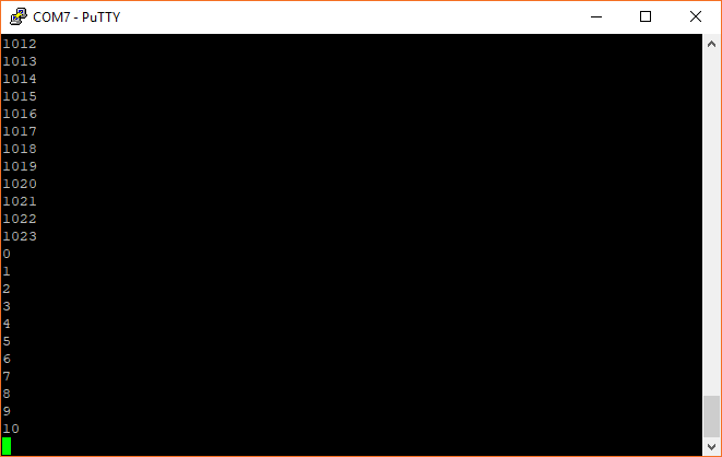
After the code has been uploaded, hold down the button (the one on the breadboard that is connected to pin 14). You should see the LED slowly brighten, turn off, and then begin the brightening animation over again as long as the button is held down.
Code to Note
Much of the code should look familiar from the previous experiment, as we are creating a machine.Pin object for our LED and another one for our button. Note that we are keeping the "drop to REPL" snippet in, as we always want a way to exit out of our code's main loop.
The main difference is that we are creating machine.PWM object out of our machine.Pin object (the pin object that we've created with the pwm_pin variable). With the machine.PWM object, we can call the pwm.duty() method, which allows us to control the amount of on vs. off time on pin 27. A duty cycle of 0 means that the pin is always 0 V. A duty cycle of 511 (about half of 1023) means that pin 27 should rapidly switch between 0 V and 3.3 V equally (50%). Finally, a duty cycle of 1023 means that pin 27 should be always on (always at 3.3 V). Again, refer to the Pulse Width Modulation tutorial for more information on pwm and duty cycles.
By placing pwm.duty() inside a for loop, we can increase the brightness one stage at a time with a 2 ms delay between each stage. This ultimately gives the effect of a slowly increasing LED brightness.
Notice that we check for button 0 at the beginning of the for loop. That means that you need to hold down button 0 until the for loop (LED animation) has completed one iteration before the program realizes you've pressed the button (and should therefore exit to REPL). To help you know when you have successfully exited the program into REPL, we added repl_led.value(1) to turn on the onboard blue LED.
Experiment 3: Analog Input
The ESP32 has a few pins that can be configured as analog-to-digital converters (ADCs). Unfortunately, they are slightly more complicated to use than some other microcontrollers. Most importantly, know that pins 32-39 are supported in MicroPython as ADCs and that we recommend using pins 36-39 for analog input due to the available preamplifier.
This video and this forum post can help you learn more about how the preamp and ADC work on the ESP32.
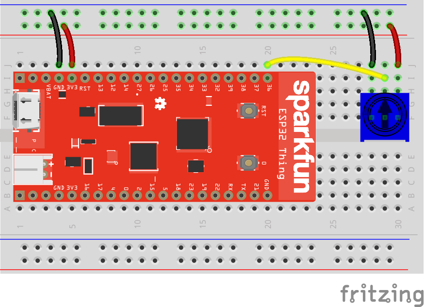
We are going to add a simple potentiometer to the ESP32 and measure the voltage from it. Note that the on-chip ADC is not the best, as it seems to exhibit some non-linear behavior. If you need a more accurate ADC, we recommend something like this SPI ADC chip.
Hardware Connections
Connect a potentiometer to the ESP32 as per the following diagram:
Code: Do the Twist
In a new file, enter the following Python code:
language:python
import machine
import sys
import utime

# Pin definitions
repl_button = machine.Pin(0, machine.Pin.IN, machine.Pin.PULL_UP)
repl_led = machine.Pin(5, machine.Pin.OUT)
adc_pin = machine.Pin(36)

# Create an ADC object out of our pin object
adc = machine.ADC(adc_pin)

# 11 dB attenuation means full 0 - 3.3V range
adc.atten(adc.ATTN_11DB)

# Blink forever
while True:

    # If button 0 is pressed, drop to REPL
    if repl_button.value() == 0:
        print("Dropping to REPL")
        repl_led.value(1)
        sys.exit()

    # Read ADC and convert to voltage
    val = adc.read()
    val = val * (3.3 / 4095)
    print(round(val, 2), "V")

    # Wait a bit before taking another reading
    utime.sleep_ms(100)
Save the code with a name like adc.py. Open a command terminal, and navigate to the directory with your adc.py file. Press button 0 on your ESP32 to drop to REPL, and enter the following commands into your terminal (changing <PORT> to your particular port name/location):
language:shell
cp adc.py main.py
ampy --port <PORT> put main.py
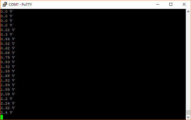
Open a serial terminal connection to the ESP32. You should see voltage readouts being rapidly printed to the screen. Try turning the potentiometer knob to adjust the voltage.

As you turn the knob, the voltages being printed to the screen should update.
Code to Note
Similar to how we created a machine.PWM object in the last section, we create a machine.ADC object here using the pin object we created for pin 36. Because we are using the preamplified ADC pins, we can set the attenuation:
language:python
adc.atten(adc.ATTN_11DB)
Our options for setting attenuation include:
ATTN_0DB- no attenuationATTN_2_5DB- 2.5 dB of attenuationATTN_6DB- 6 dB of attenuationATTN_11DB- 11 dB of attenuation
The ESP32 ADC video at 3:57 gives a great overview of the different attenuation options. Generally, you will want to use 11 dB, as that gives you the full range of values from 0 to 3.3 V. 0 dB is great if you only need 0 to 1 V of analog-to-digital conversion (much like how the ADC on the ESP8266 works).
Note that the ADC is not completely accurate. Even in the full 0 to 3.3 V range, many of the values seem to be around 0.2 V off. You can test this with a multimeter to verify.
In our while loop, we get a numerical value from the ADC with adc.read(). This function returns a whole number between 0 and 4095. Because we know that 0 refers to 0 V and 4095 refers to 3.3 V, we can roughly determine our measured voltage with:
language:python
val = val * (3.3 / 4095)
We start with 0...4095 in val and then multiply that value by the quotient of (3.3 / 4095). This results in the decimal point value of temperature (in Celsius), which we store back into the val variable. Decimal point values are stored as floating point numbers, which you can learn more about here.
We print our floating point number to the screen with the following line:
language:python
print(round(val, 2), "V")
round(val, 2) says that we should round our number to two decimal places. The comma (,) followed by another string tells the interpreter that it should print a space followed by our string ("V" in this case) on the same line as our printed voltage value. This allows us to add units to the printout.
Finally, we wait 100 ms before returning to the top of loop, where we check for button 0 press each iteration.
Experiment 4: I2C
Inter-Integrated Circuit (I2C) is a communication protocol designed to allow one "master" chip to communicate with several "device" chips on the same bus. Many modern sensors rely on I2C for communication, as it is a relatively easy protocol to implement and requires only 2 signal lines. If you would like to learn more about how I2C works, see this tutorial.
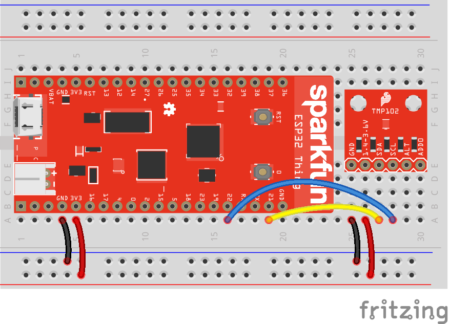
In this experiment, we are going to connect a TMP102 temperature sensor to the ESP32 Thing and read the ambient temperature.
Hardware Connections
Connect the TMP102 to the ESP32 as follows:
Code: It's Getting Hot in Here
In a new file, enter the following code:
language:python
import machine
import sys
import utime

###############################################################################
# Parameters and global variables

# Pin definitions
repl_button = machine.Pin(0, machine.Pin.IN, machine.Pin.PULL_UP)
repl_led = machine.Pin(5, machine.Pin.OUT)
sda_pin = machine.Pin(21)
scl_pin = machine.Pin(22)

# Create an I2C object out of our SDA and SCL pin objects
i2c = machine.I2C(sda=sda_pin, scl=scl_pin)

# TMP102 address on the I2C bus
tmp102_addr = 0x48

# TMP102 register addresses
reg_temp = 0x00
reg_config = 0x01

###############################################################################
# Functions

# Calculate the 2's complement of a number
def twos_comp(val, bits):
    if (val & (1 << (bits - 1))) != 0:
        val = val - (1 << bits)
    return val

# Read temperature registers and calculate Celsius
def read_temp():

    # Read temperature registers
    val = i2c.readfrom_mem(tmp102_addr, reg_temp, 2)
    temp_c = (val[0] << 4) | (val[1] >> 5)

    # Convert to 2s complement (temperatures can be negative)
    temp_c = twos_comp(temp_c, 12)

    # Convert registers value to temperature (C)
    temp_c = temp_c * 0.0625

    return temp_c

# Initialize communications with the TMP102
def init():

    # Read CONFIG register (2 bytes) and convert to integer list
    val = i2c.readfrom_mem(tmp102_addr, reg_config, 2)
    val = list(val)

    # Set to 4 Hz sampling (CR1, CR0 = 0b10)
    val[1] = val[1] & 0b00111111
    val[1] = val[1] | (0b10 << 6)

    # Write 4 Hz sampling back to CONFIG
    i2c.writeto_mem(tmp102_addr, reg_config, bytearray(val))

###############################################################################
# Main script

# Print out temperature every second
while True:

    # If button 0 is pressed, drop to REPL
    if repl_button.value() == 0:
        print("Dropping to REPL")
        repl_led.value(1)
        sys.exit()

    # Read temperature and print it to the console
    temperature = read_temp()
    print(round(temperature, 2), "C")
    utime.sleep(1)
Save the file with a name such as i2c.py. In a command terminal, navigate to the directory with your i2c.py file. Hold down button 0 until you see the blue LED turn on to let you know that you have entered the REPL. In the command terminal, enter the following commands (change <PORT> to your port name/location):
language:shell
cp i2c.py main.py
ampy --port <PORT> put main.py
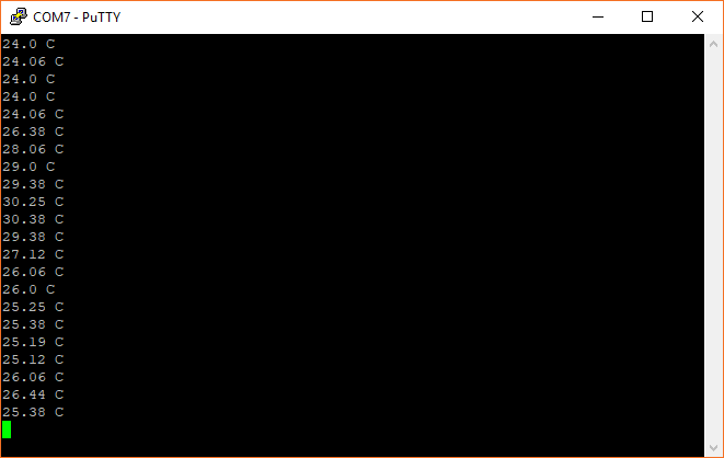
Open a serial connection to the ESP32, and you should see temperature value (in Celsius) being reported once per second.

Try breathing warm air onto the TMP102 sensor to see if you can change the temperature values.
Code to Note
This code is much longer than our previous examples. This is due to us needing to send configuration information to the TMP102, read temperature, and then perform some calculations on the raw data to get a human-readable temperature value.
Every time we want to communicate with the TMP102, we send out its address (0x48) on the bus. From there, we usually send the memory location (address) of the register that we intend to read from or write to on the TMP102. For most I2C devices, a register is a location in the device's memory that stores 1 byte (8 bits) of data. Some registers control the function of the device (for example, the CONFIG register in the TMP102). Other registers hold sensor data readings (such as the TEMP register in the TMP102) that we must read from.
To communicate on an I2C bus, we create a machine.I2C object, passing it the pins we intend to use for SDA and SCL:
language:python
i2c = machine.I2C(sda=sda_pin, scl=scl_pin)
We use the following command to read 2 bytes from the temperature register in the TMP102:
language:python
val = i2c.readfrom_mem(tmp102_addr, reg_temp, 2)
These values are stored as a list [x, y] in the val variable. By looking at the TMP102 datasheet, we see that temperature is 12 bits. When we read the two bytes that contain this reading, we need to remove the last 4 bits from the second byte. We also move the first byte over 4 bits:
language:python
temp_c = (val[0] << 4) | (val[1] >> 5)
In order to display negative numbers for the temperature, values from the TMP102 come in the form of Two’s Complement. In this, the first bit of the 12-bit number determines if the value is positive or negative (0 for positive, 1 for negative). See this article to learn more about Two’s Complement.
To convert a Two’s Complement number to a negative number in Python, we check to see if the first bit is 0 or 1. If it is 0, then we just use the number as is (it’s positive!). If it’s a 1, we subtract the max negative number of the Two’s Complement (212=4096 in this case) from our number.
language:python
if (val & (1 << (bits - 1))) != 0:
    val = val - (1 << bits)
Finally, we multiply this two's complement number by 0.0625 to convert the raw value into a Celsius value. Refer out Table 5 in the TMP102 datasheet to see how the raw-to-Celsius calculation is performed.
Experiment 5: WiFi
While the possibilities of interacting with hardware directly connected to the ESP32 are endless, some real fun can be had connecting to the Internet. By being able to send and receive data to servers across the Internet, the ESP32 can download current weather or time data, upload sensor data, and respond to events (e.g. on Twitter) in real time. This is just the beginning of exploring the Internet of Things (IoT).
To demonstrate accessing the Internet, we will write a quick MicroPython program that connects to a local WiFi and downloads the example.com web page using an HTTP GET command.
Hardware Connections
We'll keep it simple this time--just the ESP32 Thing will be needed. We're going to use its built-in WiFi radio, get a web page, and then send the downloaded HTML contents over the serial connection.
Code: GET Some
In a new file, enter the following code (change <YOUR WIFI SSID> to the name of your WiFi network name and <YOUR WIFI PASSWORD> to the name of your WiFi's password--note that the name and password should be in quotation marks ""):
language:python
import machine
import sys
import network
import utime
import urequests

# Pin definitions
repl_button = machine.Pin(0, machine.Pin.IN, machine.Pin.PULL_UP)
repl_led = machine.Pin(5, machine.Pin.OUT)

# Network settings
wifi_ssid = "<YOUR WIFI SSID>"
wifi_password = "<YOUR WIFI PASSWORD>"

# Web page (non-SSL) to get
url = "http://example.com"

# Create a station object to store our connection
station = network.WLAN(network.STA_IF)
station.active(True)

# Continually try to connect to WiFi access point
while not station.isconnected():

    # Try to connect to WiFi access point
    print("Connecting...")
    station.connect(wifi_ssid, wifi_password)

    # Check to see if our REPL button is pressed over 10 seconds
    for i in range(100):
        if repl_button.value() == 0:
            print("Dropping to REPL")
            repl_led.value(1)
            sys.exit()
        utime.sleep_ms(100)

# Continually print out HTML from web page as long as we have a connection
while station.isconnected():

    # Display connection details
    print("Connected!")
    print("My IP Address:", station.ifconfig()[0])

    # Perform HTTP GET request on a non-SSL web
    response = urequests.get(url)

    # Display the contents of the page
    print(response.text)

    # Check to see if our REPL button is pressed over 10 seconds
    for i in range(100):
        if repl_button.value() == 0:
            print("Dropping to REPL")
            repl_led.value(1)
            sys.exit()
        utime.sleep_ms(100)

# If we lose connection, repeat this main.py and retry for a connection
print("Connection lost. Trying again.")
Save the file with a name like wifi.py. In a command terminal, navigate to the directory where wifi.py is stored. Hold down button 0 on the ESP32 Thing to exit its currently running program. Back in the command terminal, enter the following commands (<PORT> should be changed to your serial port name/location):
language:shell
cp wifi.py main.py
ampy --port <PORT> put main.py
Open a serial connection to the ESP32, and you should see your ESP32 connect to your WiFi network and then download the example.com HTML page. If you see text like the one below, you know that it worked:
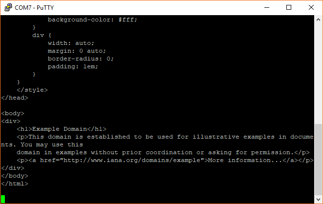
If you are unable to connect and download the page, double-check the SSID and password in the code. Additionally, some network configurations do not work well with the ESP32, which means you might need to try a different network.
Code to Note
In this example, we're relying on the network and urequests modules to handle much of the networking for us. We use the network module to perform the low-level communication over WiFi, including connecting to our Wifi access point. To create a connection to our WiFi access point, we first create a WLAN object and use network.STA_IF to tell the ESP32 that we want to use it as a client that connects to a separate access point:
language:python
station = network.WLAN(network.STA_IF)
station.active(True)
From there, we attempt to establish a connection with the access point:
language:python
while not station.isconnected():

    # Try to connect to WiFi access point
    print("Connecting...")
    station.connect(wifi_ssid, wifi_password)
The line station.connect(wifi_ssid, wifi_password) is what actually performs the connection. We wrap this up in a while loop that continually checks to see if we have a connection. This way, if no connection is established, the program will not move forward and try to perform a GET request on a website. Notice that we also include our "Drop to REPL" button check in this while loop, too, in case the ESP32 gets stuck here.
Once we have a connection, we use the urequests module to perform our GET request on example.com:
language:python
response = urequests.get(url)
This returns a Response object that contains all the information returned by the server. We can view the response in text form with the command:
language:python
print(response.text)
We then wait for 10 seconds before requesting the page again. During those 10 seconds, we check for a button 0 push every 100 ms.
If you would like to learn more about networking in MicroPython, see the network module documentation.
Troubleshooting
As with all things programming, things have a habit of not working on the first try, and that's OK! Trying to figure out what is going wrong with your code might be a little tricky with MicroPython, but it can be done.
Cannot Upload Program
If you cannot upload your program and get an error such as ampy.pyboard.PyboardError: failed to access COM7 from ampy, it means that another program is using the serial connection to your ESP32. Take a look at all of your open programs and close or disconnect anything that has an open serial connection to your ESP32.
If you are on Windows and your port number is higher than 10, ampy may give you an error message like so: ampy.pyboard.PyboardError: failed to access \\.\COM24. There is a known issue with Python's recognition of Windows ports above 10, but ampy does not take this into account, so we must format our port explicity for Python. Try formatting your COM port as you see it here (replacing <PORT> with your port number/location): \\.\<PORT>
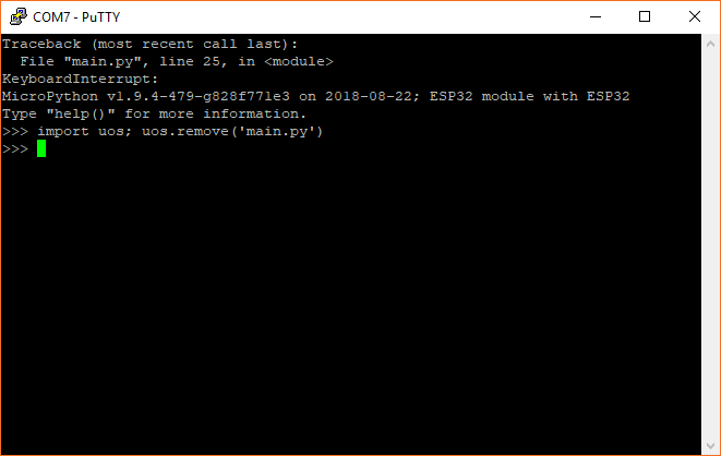
If, on the other hand, ampy gives you an error message like ampy.pyboard.PyboardError: could not enter raw repl, it means that the ESP32 is running a program and not in REPL mode. If you were following this guide exactly, you should be able to press button 0 on the ESP32 Thing to exit your program to REPL. If you forget to add some "Drop to REPL" code in your program, you will need to manually stop your code and remove main.py:
- Open a serial terminal program and connect to your ESP32.
- In your serial terminal, press ctrl + c to send the SIGINT interrupt signal to the program running on the ESP32. You should see a REPL prompt (
>>>) appear. - In REPL, enter the following commands:
import uos; uos.remove('main.py'). This will import the uos module, which allows us to manipulate files and then deletes the main.py file, which will prevent our program from running in the future. - Close your serial terminal program and try uploading your main.py again.
Debugging
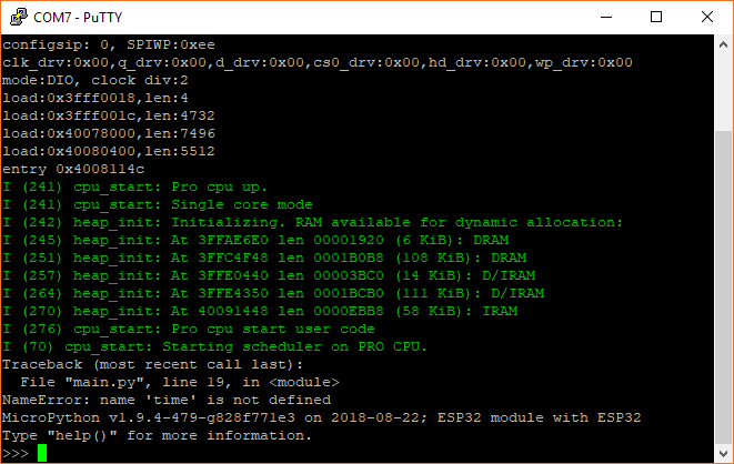
If you were able to upload your program but nothing runs, you could have a syntax error in your code or a runtime error.
The first step is to use your serial terminal program to connect to your ESP32. Press the reset button (labeled RST on the board). If there are syntax errors in your code, you should see them printed out to the serial terminal.
If you do not see any syntax errors, you may have a runtime error (e.g. your code is doing something that you did not intend for it to do). There are many ways to debug runtime errors, but one of the most common methods is to add print() statements in your code to see what is happening at that moment in your program (or to check if your program is getting to that point at all).
Resources and Going Further
We hope that this tutorial has given you a starting place for using MicroPython on the ESP32 Thing for both controlling hardware and interacting with other devices across the Internet. Good luck on your next hardware or IoT project! If you would like to dig deeper into MicroPython, we recommend the following resources:
- MicroPython documentation
- MicroPython documentation for the ESP8266 - Closest thing you will find to ESP32 MicroPython documentation (as of the time of this tutorial's writing)
- Video overview of why MicroPython works well on the ESP32
Resource Links:
- ESP32 Thing Datasheet
- ESP32 Thing Schematic
- Text Editors:
How-To Links:
- How to Load MicroPython on a Microcontroller Board
- ESP32 ADC Video
- ESP32 ADC MicroPython Forum
- Networking in MicroPython
Concept Links:
- Pulse Width Modulation
- I2C Tutorial
- Analog-to-Digital Conversion (ADC)
- Serial Peripheral Interface (SPI)
- UART
- Two's Complement
- Logic Shifting
- Pull Up Resistors
Looking for more MicroPython ideas? Check out these other projects (not necessarily on an ESP32):