MicroMod mikroBUS™ Carrier Board Hookup Guide
Necto Studio Example
In this example, we will be using the Weather Click board™ and outputting the BME280 sensor's data to the UART Terminal. To get started, follow the instructions below.
Required Materials
For this example, users will need a MicroMod mikroBUS™ carrier board, STM32 processor board, phillips head screwdriver, Weather Click, MIKROE CODEGRIP for STM32 programmer, 50-100mil JTAG adapter, and access to a computer with the Necto Studio and the CODEGRIP Suite installed:
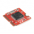
SparkFun MicroMod STM32 Processor
DEV-17713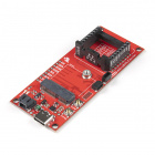
SparkFun MicroMod mikroBUS Carrier Board
DEV-18710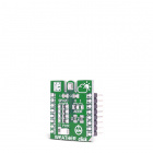
MIKROE Weather Click
SEN-18823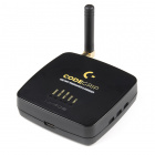
MIKROE CODEGRIP for STM32
PGM-19105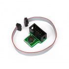
MIKROE 50-100mil Adapter
PGM-19220Users will also need some soldering equipment and a JTAG header to connect the programmer to the board:


Weller WLC100 Soldering Station
TOL-14228To read the data output from the Weather Click example code, users will also need a Terminal Click, serial breakout board, jumper wires, and a USB cable:

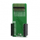
MIKROE Terminal Click
DEV-18961For users who haven't soldered before and/or need to install the CH340 driver for the Serial Basic breakout, the following tutorials should be reviewed before proceeding further:
How to Solder: Through-Hole Soldering
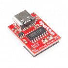
SparkFun Serial Basic CH340C Hookup Guide
How to Install CH340 Drivers
Getting Started with Necto Studio
Hardware Assembly
Hardware assembly is relatively straight forward, attach the STM32 processor board to the MicroMod slot, solder on the JTAG header, insert the Click boards™ into the mikroBUS™ socket, connect the carrier board to the programmer, connect the Serial Basic breakout, and then link the programmer to the computer.
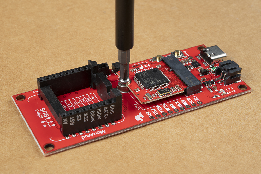
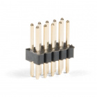
If users haven't done so, solder the JTAG header to the board.

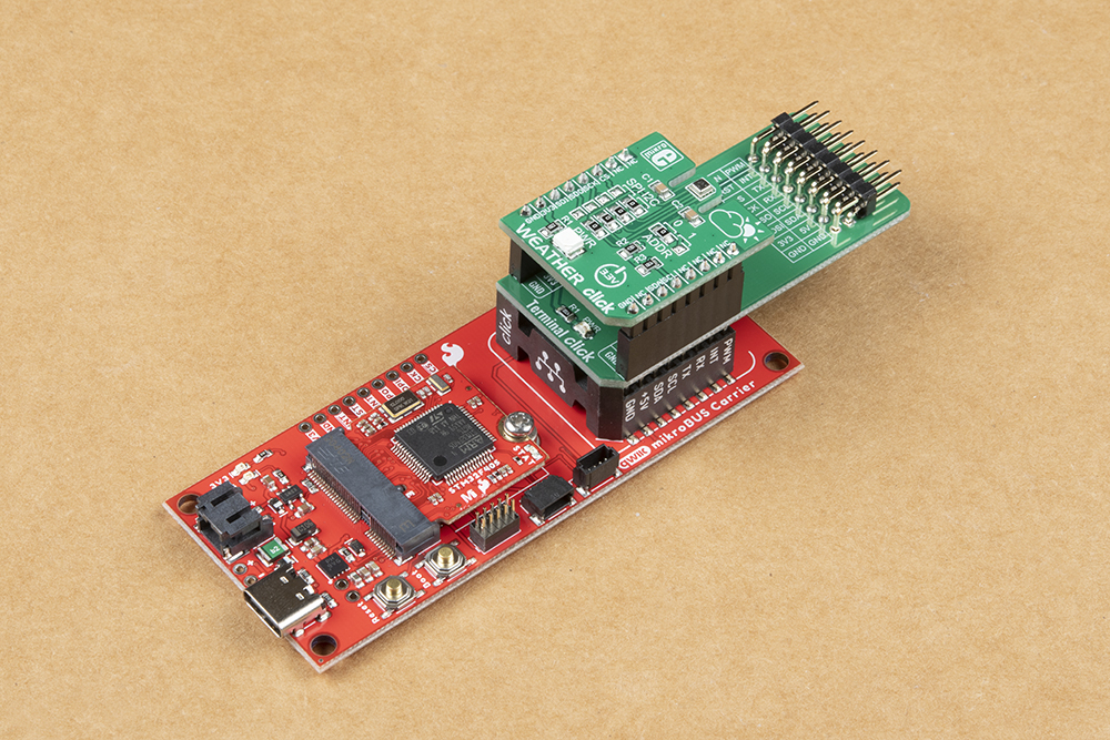
To breakout the serial pins of the mikroBUS™ socket, the Terminal Click board™ needs to be stacked between the Weather Click board™ and the mikroBUS™ socket.
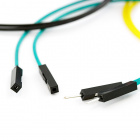
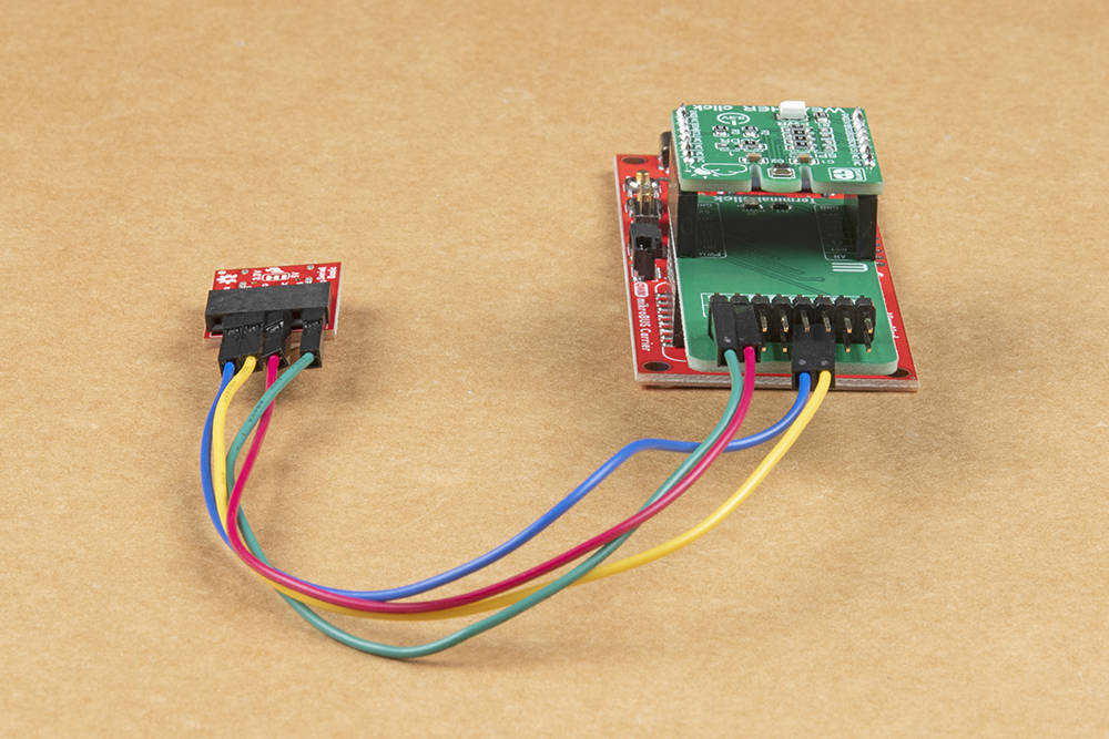
Once the serial pins have been broken out with the Terminal Click board™, users can access the serial pins with a Serial Basic breakout and some jumper wire.
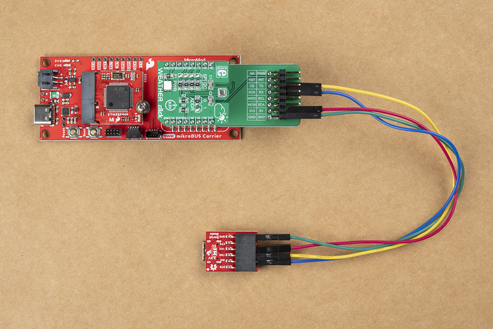
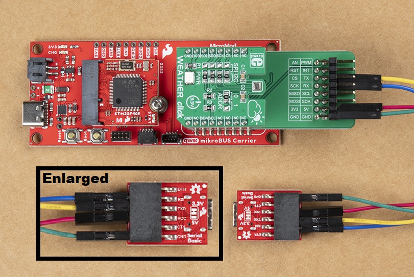
The pin connections are summarized in the table below and illustrated more closely in the images (click to enlarge).
| Terminal Click™ | Serial Breakout | Description |
|---|---|---|
RX |
RXI |
Serial data output from Click board™ to MCU |
TX |
TXO |
Serial data output from MCU to Click board™ |
3.3V |
VCC |
Power input to mikroBUS socket™ |
GND |
GND |
Ground |
Finally, connect the CODEGRIP programmer with a JTAG adapter. Then, connect both the programmer and Serial Basic breakout to the computer.
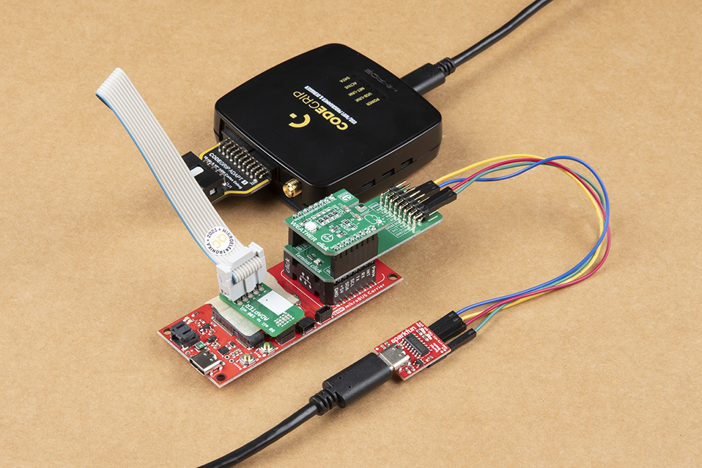
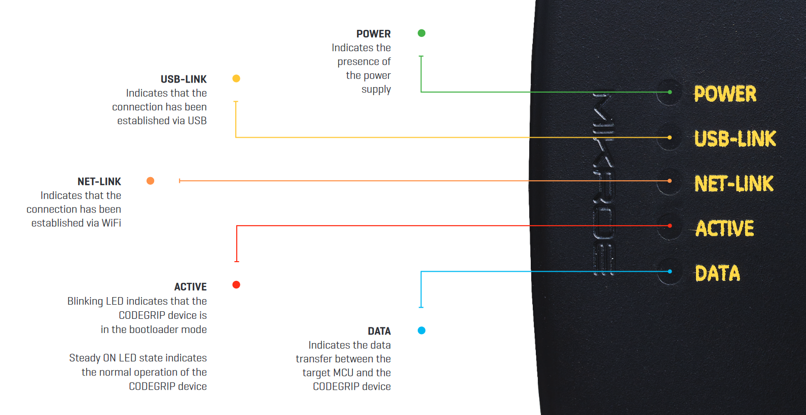
If everything was connected properly, the POWER and ACTIVE, and USB LINK LED indicators on the programmer will turn on. Once the ACTIVE LED indicator stops blinking, the CODEGRIP programmer is ready to be used.
Software Setup
On the computer, users should have Necto Studio and the CODEGRIP Suite installed.
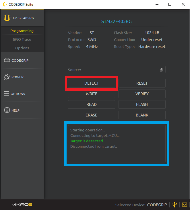
In the CODEGRIP Suite, users will need to link with the programmer and configure the programming target:
- MCU:
STM32F4045RG - Protocol:
SWD - Connection:
Under reset - Halt on Connect:
Enabled
NOTE: Users won't need to enable the power output on the programmer because the power connection from the Serial breakout board. This will provide enough power for the carrier board.After the programmer has been linked and the MCU target has been configured, users should be able to perform a target verification with the detect function.
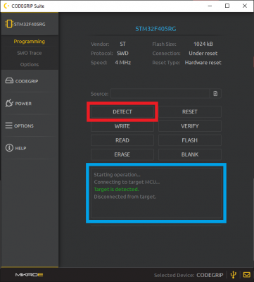 Detecting the target MCU in the CODEGRIP Suite. (Click to enlarge)
For more details, check out the Programmer Configuration section of the Necto Studio getting started guide.
- MCU:
In Necto Studio, if users should have already created a hardware configuration through the Setups page. The hardware configuration should include the following options:
- mikroC AI for ARM compiler
- mikroSDK (latest)
- MicroMod Carrier Board
- STM32F4045RG-Tx (should be only option)
- No display
- CODEGRIP Programmer
- To be able to debug and program the MCU from Necto Studio, users will want to configure the following target option parameters:
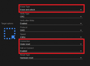 Target options for the CODEGRIP programmer in Necto Studio. (Click to enlarge)
 - Erase Type:
Erase and unlock - Connection:
Under reset - Hold on Connect:
Enabled
- To be able to debug and program the MCU from Necto Studio, users will want to configure the following target option parameters:
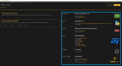 Hardware configuration in Setups page of Necto Studio. (Click to enlarge)
For more details, check out the Setups section of the Necto Studio getting started guide.
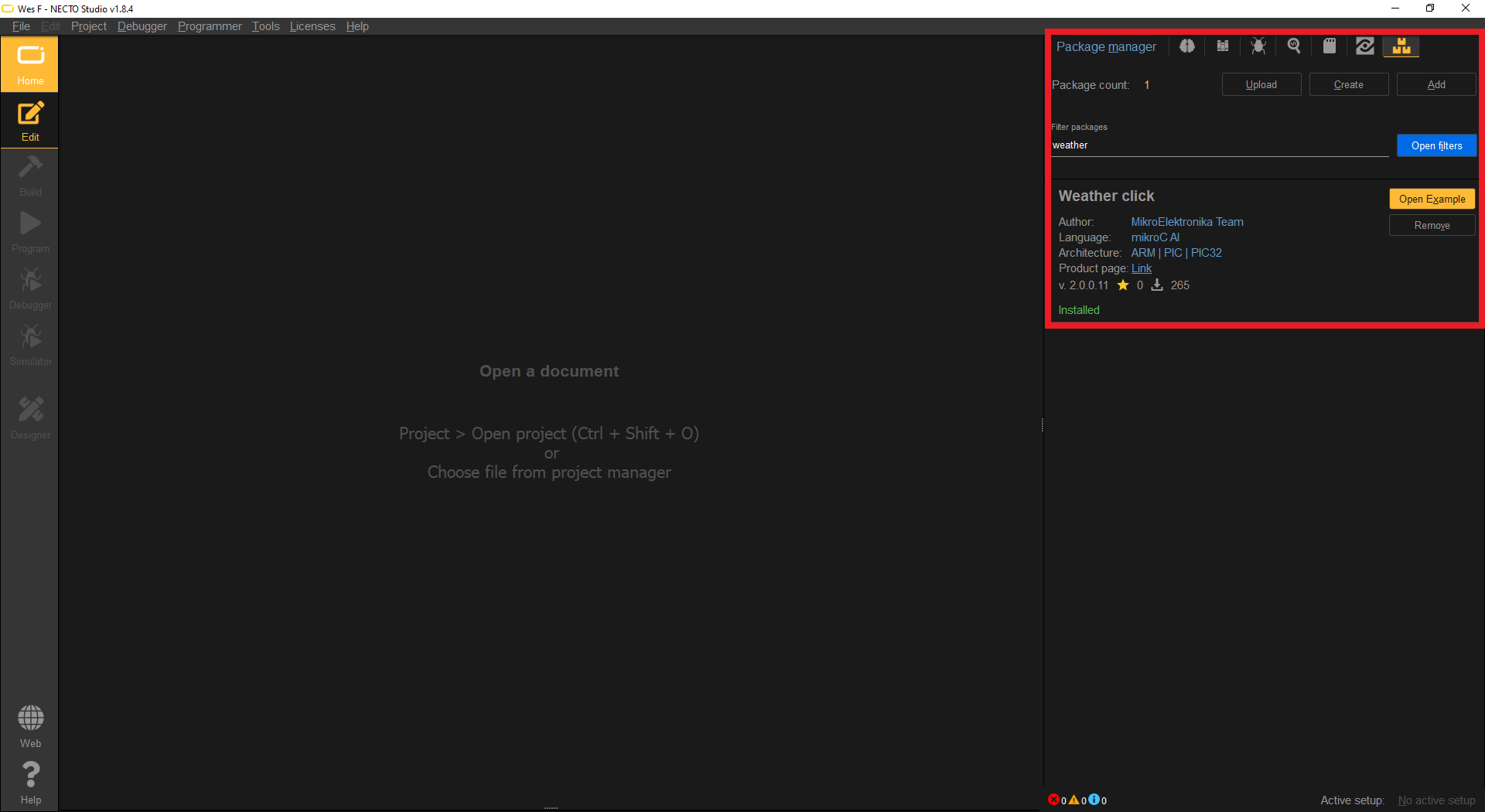
In the package manager of Necto Studio, users will need to install the Weather Click library.
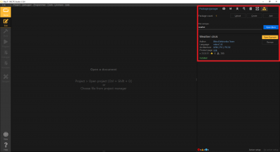 The Weather Click library installed through the Package Manager page of Necto Studio. (Click to enlarge)
For more details, check out the Package Manager section of the Necto Studio getting started guide.
Once the Weather Click library has been installed, users will have access the associated example for the library. From the Package Manager page, users should be able to create a new project by clicking on the Open Example button.
- Users will then need to select their hardware setup. Users should select the hardware configuration for they created for the MicroMod mikroBUS™ carrier board.
- For more details, check out the Package Manager section of the Necto Studio getting started guide.


Running the Example Code
After the project has been created for the Weather Click example, users will be able to program the example onto their carrier board. This can be done either of two methods; however, the simplest method would be to use the Program button in Necto Studio.
To receive and display the serial data output from the example, users will need to open the UART Terminal in Necto Studio by selecting Tools > UART Terminal from the drop down menu.
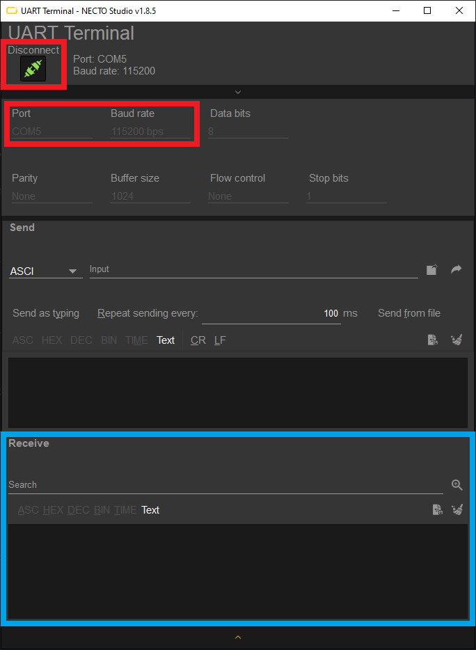
In the UART Terminal, users will need to:
- Select the Port for the Serial Basic breakout
- Set the Baud rate to
115200 bps Click on the Connect button
 UART Terminal configuration to connect to the Serial Basic breakout. (Click to enlarge)
If the connection succeeds, users should then see data from the BME280 sensor being displayed in the Receive text box.