MicroMod mikroBUS™ Carrier Board Hookup Guide
Hadware Assembly
For those unfamiliar with the MicroMod ecosystem, be sure to review the Getting Started with MicroMod guide.
Getting Started with MicroMod
MicroMod Processor Board
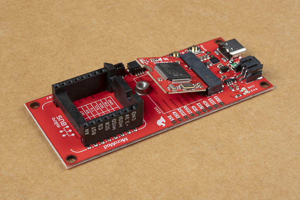
To get started users will need a compatible processor board. Insert the MicroMod processor board into the M.2 socket for the processor board at an angle, with its edge connector aligned to the matching slots.
When inserted properly, the processor board will rest at an angle:
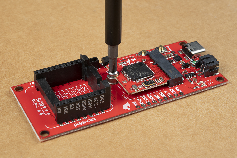
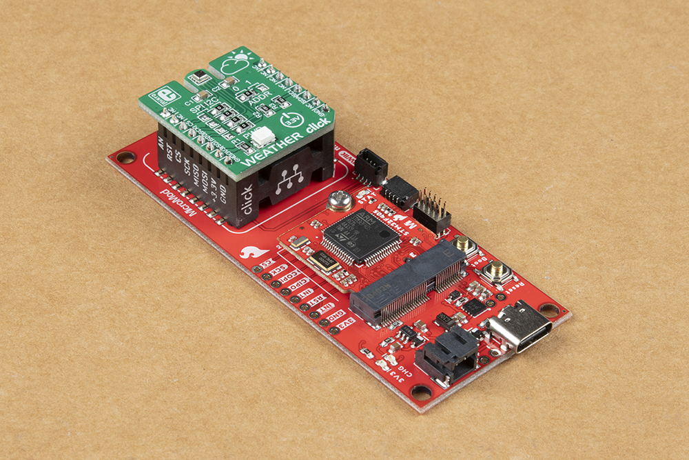
To secure the processor board, gently hold down on the board and attach the M.2 screw with a Phillip's head (PH0 or PH1) screw driver. Below, is an example of an assembled MicroMod system:
JTAG Programming (preferred)
To program the processor board on the MicroMod mikroBUS™ carrier board, users will need a JTAG adapter to convert the .1" (100 mil) header spacing on the programmer cable to the .05" (50 mil) header spacing of the JTAG pins on the MicroMod mikroBUS™ carrier board. Additionally, users will need to solder on a compatible JTAG header to their board.

Programming the MicroMod mikroBUS™ carrier board through the JTAG pins. (Click to enlarge)
JTAG Header
With the preferred programming method, Necto Studio, users will program the processor board on the MicroMod mikroBUS™ carrier board through the JTAG pins. Therefore, users will need to solder on a JTAG header for the programmer to connect to.

JTAG Adapter
With the recommended programmer, users will need an adapter to convert the .1" (100 mil) header spacing on the programmer cable to the .05" (50 mil) header spacing of the pins on board, .
Note: Users should verify that the pinout for the programmer and adapter match up to the corresponding pins of the MicroMod mikroBUS™ carrier board to avoid damaging the MCU of the processor board. Additionally, preventative measures should be taken if there is a risk that the pins from the adapter could contact the processor board.
The JTAG adatpter with pins exposed over the processor board. (Click to enlarge)

Tape used to prevent shorts on the processor board. (Click to enlarge)
USB Programming (not preferred)
A processor board utilized on the MicroMod mikroBUS™ carrier board, can also be connect to a computer with a USB-C cable and programmed with the Arduino IDE. Depending on the processor board, users may need to install drivers (if they have not done so already).
Note: Make sure that the correct board definitions are installed in the Arduino IDE, for the selected processor board. For help installing board definitions, use the MicroMod processor boards landing page and review the associated hookup guide for that hardware.
Installing Board Definitions in the Arduino IDE
To upload a sketch to the STM32 processor board (recommended), users will need to:
- Connect a USB-C cable between the board and the computer
- Hold down the
BOOTbutton - Toggle the
RESETbutton - Hit the upload button in the Arduino IDE, to program the sketch
- Make sure to use the correct setting in the Tools menu for the processor board
- Once the upload process has completed in the Arduino IDE, the
BOOTbutton can be released
Battery
For remote applications, the MicroMod mikroBUS™ carrier board can be powered through its 2-pin JST battery connector. Additionally, users may be interested in utilizing a solar panel and USB-C cable to recharge their battery.
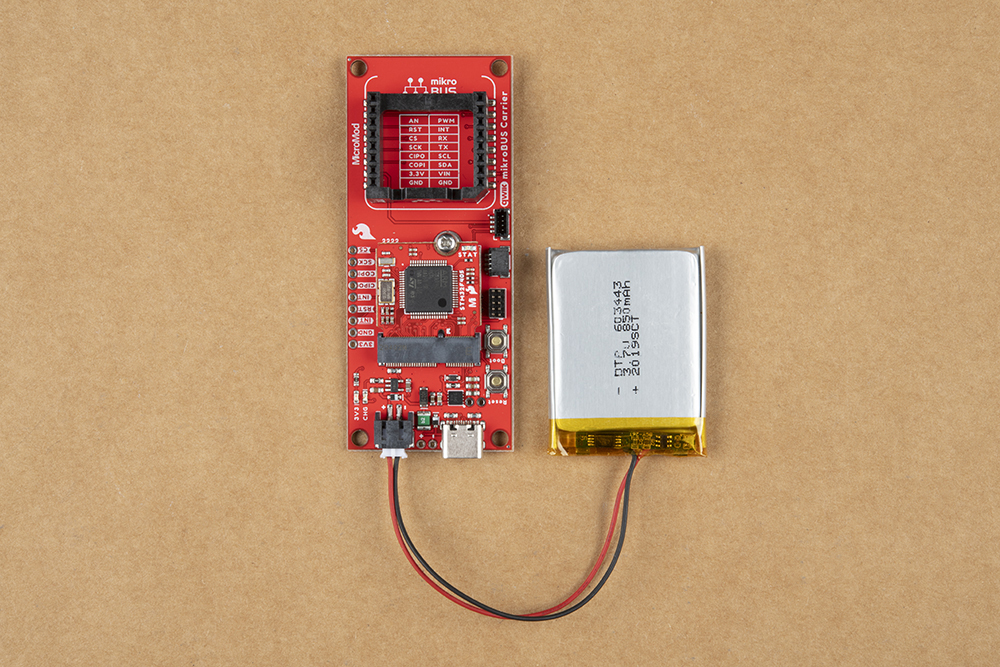
The MicroMod mikroBUS™ carrier board with a battery attached. (Click to enlarge)
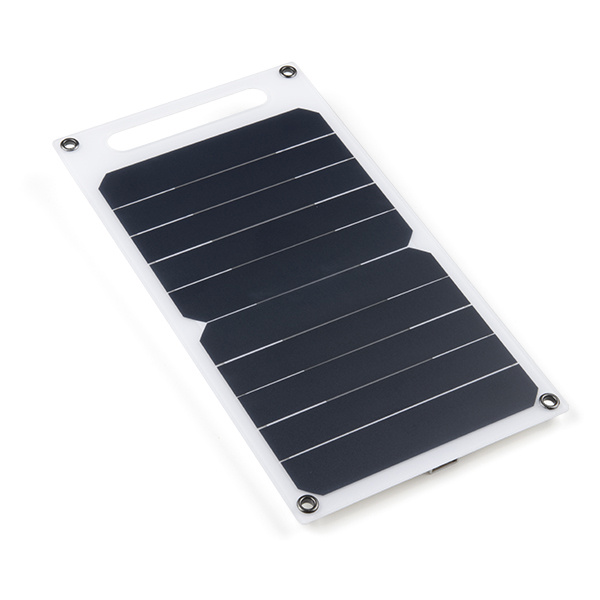
Solar Panel Charger - 10W
PRT-16835
Note: DO NOT remove batteries by pulling on their wires. Instead, it is recommended that pair of dikes (i.e. diagonal wire cutters), pliers, or tweezers be used to pull on the JST connector housing, to avoid damaging the battery wiring.
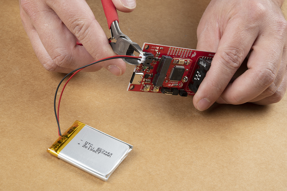
Using a pair of dikes to disconnect a battery. (Click to enlarge)
mikroBUS™ Socket
The MicroMod mikroBUS™ carrier board has a mikroBUS™ Socket, where a Click board™ can be inserted.
Note: To remove a Click board™, slowly and carefully wiggle it out of the mikroBUS™ socket to avoid bending the header pins on their Click board™.
The header also allows users to connect jumper wires to devices that may not have the mikroBUS™ pin layout to interface with.

Serial Data Output
Note: Some of the examples for the Click board™ libraries in Necto Studio, utilize a serial data output to verify functionality. In order to access the serial data output from the mikroBUS™ socket, users can use a Terminal Click Board™, serial-to-UART adapter, and jumper wires.
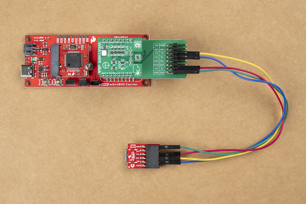
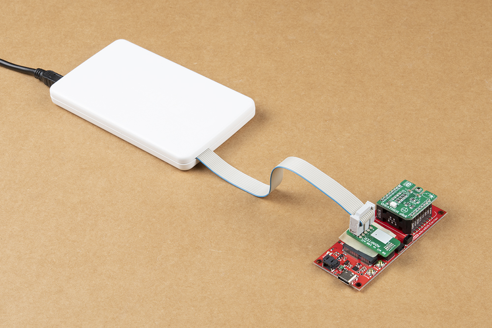
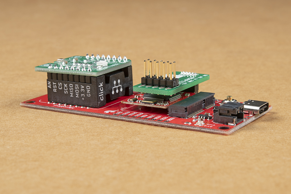
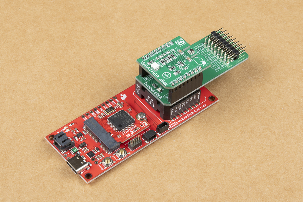
Weather and Terminal Click boards™ inserted into the mikroBUS™ socket of the MicroMod mikroBUS™ carrier board and connected to a serial-to-UART adapter. (Click to enlarge)
To breakout the pins of the mikroBUS socket™, a Terminal Click board™ can be stacked between a Click board™ and the mikroBUS socket™.
Once the serial pins have been broken out with the Terminal Click board™, users can access the serial pins with a serial-to-UART adapter and some jumper wire. The pin connections are summarized in the table below and illustrated in the following images.
| Terminal Click™ | Serial Breakout | Description |
|---|---|---|
RX |
RXI |
Serial data output from Click board™ to MCU |
TX |
TXO |
Serial data output from MCU to Click board™ |
3.3V |
VCC |
Power input to mikroBUS socket™ |
GND |
GND |
Ground |
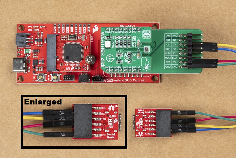
Top view of jumper wire connections. (Click to enlarge)
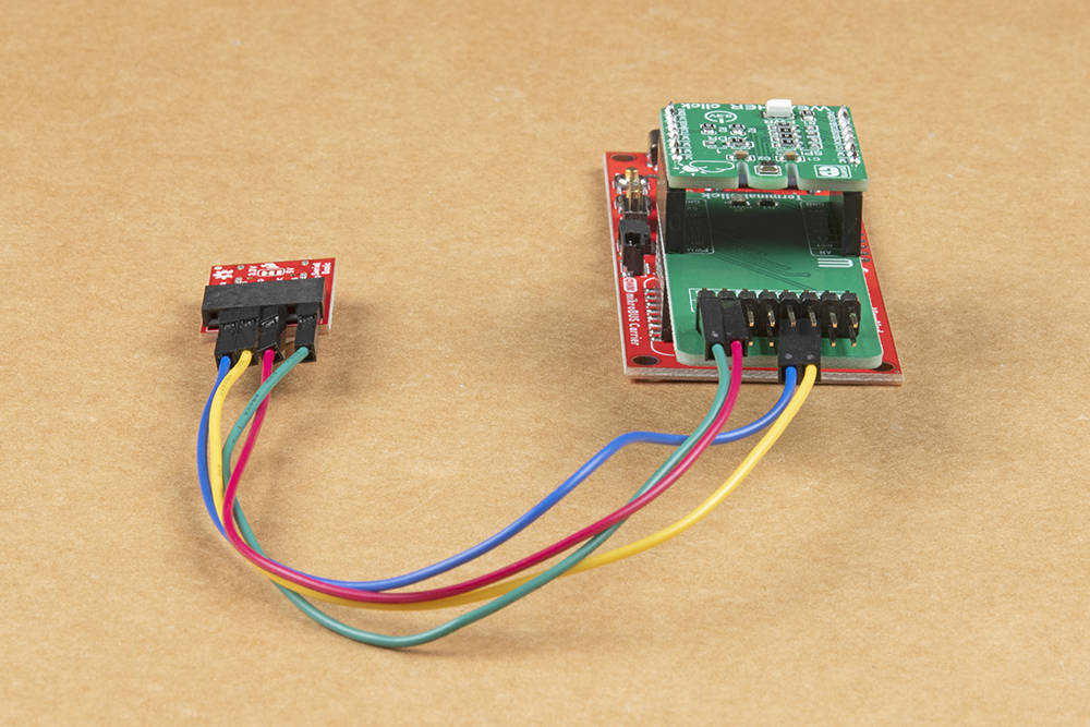
Front view of the jumper wire connections. (Click to enlarge)
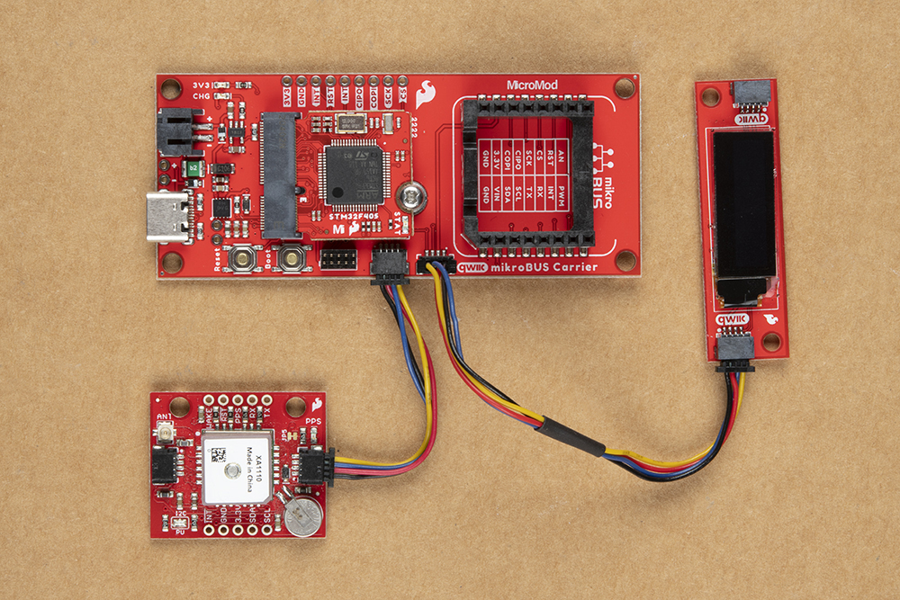
Qwiic Devices
To connect Qwiic devices to the carrier board, users will need Qwiic cables; most of these devices can also be daisy chained together. For more information, check out our Qwiic ecosystem page.