MicroMod Asset Tracker Carrier Board Hookup Guide
Arduino Examples
Once you have the MicroMod Asset Tracker Carrier Board examples and all of the required libraries installed, it is finally time to run your first example!
Example 1: Blink
Baby steps… Example1 checks that you can communicate with the MicroMod Processor Board, compile and upload code successfully.
Navigate to the location the Asset Tracker Examples repository downloaded to and open the Examples folder. In that folder you'll find all the examples. Navigate to Example1 and open the file called AssetTracker_Example1_Blink.ino in the Arduino IDE or copy the code below into a blank sketch, select your Board and Port and click "Upload".
language:c
#include "AssetTrackerPins.h" // Include the Asset Tracker pin and port definitions

#define SERIAL_PORT Serial // This is the console serial port - change this if required

#include <SparkFun_u-blox_SARA-R5_Arduino_Library.h> //Click here to get the library: http://librarymanager/All#SparkFun_u-blox_SARA-R5_Arduino_Library

// Create a SARA_R5 object to use throughout the sketch. Pass it the power pin number.
SARA_R5 assetTracker(SARA_PWR);

void setup()
{
  initializeAssetTrackerPins(); // Initialize the pins and ports (defined in AssetTrackerPins.ino)
}

void loop()
{
  digitalWrite(LED_BUILTIN, !digitalRead(LED_BUILTIN)); // Flash the STAT LED at 0.5Hz (Read-Invert-Write)
  delay(1000);
}
All Example1 does is blink the STAT LED on the Processor Board. That's all it does. Yes, really. But it proves that you have the correct Processor Board selected and that code compilation and upload works. The good stuff comes in the following examples.
Example 2: IMU
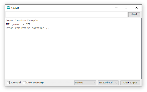
Example2 demonstrates how to get readings from the ICM-20948 Inertial Measurement Unit on the Asset Tracker. Open AssetTracker_Example2_IMU.ino and upload to the Processor Board. Now open the Serial Monitor or a terminal emulator and connect to the Processor Board at 115200 Baud. If all is well, you should see the following:
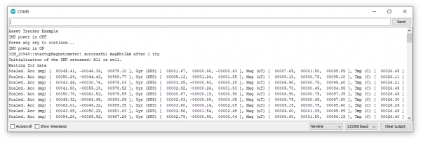
Click Send or hit Enter and you should then see the following, followed by lots of lovely IMU data scrolling up the screen:
The things to look out for are a 980 milli-g Acceleration in Z - if your board is horizontal. That's gravity. You will also see a reading of the Earth's magnetic field on one or more of the Magnetometer (Compass) axes, but the value will depend on your local Angle Of Magnetic Declination and Inclination. (Strange but true: the strongest magnetic field points downward into the ground in many places.)
Example 3: µSD Card
Example3 uses Bill Greiman's SdFat library to print a directory of all the files on your microSD card.
The usual restrictions apply: we recommend disconnecting the power to your Asset Tracker before removing or inserting the µSD card. Removing the card while powered can cause data corruption.
Example 4: MAX17048 Fuel Gauge
Example4 demonstrates how to use the MAX17048 Fuel Gauge to read the battery charge status.
Example 5: Qwiic
Example5 demonstrates how to use the Qwiic bus to talk to an external sensor attached to the Qwiic connector. The example assumes that you have a Qwiic Power Switch attached, but you can adapt the code to use whichever Qwiic board you have available. The Qwiic I2C bus is called Wire on the Asset Tracker.
Example 6: I/O Pins
Example6 demonstrates how to configure the D0, D1, A0, A1, PWM0 and PWM1 Input / Output pins.
Example 7: GNSS Antenna Power
Example7 is where we communicate with the SARA-R5 for the first time. The power for the active GNSS antenna is controlled by the SARA GPIO2 pin. When the SARA is on and GPIO2 is high, the 3.3V antenna power is enabled. We need to instruct the SARA to enable GPIO2 and set it high via the UART interface.
The example code calls enableGNSSAntennaPower(); and disableGNSSAntennaPower(); which do the heavy lifting for you. Those functions are defined in AssetTrackerPins.in and in turn call the SARA-R5 library:
language:c
assetTracker.setGpioMode(assetTracker.GPIO2, assetTracker.GPIO_OUTPUT, 1); // Enable
and
language:c
assetTracker.setGpioMode(assetTracker.GPIO2, assetTracker.GPIO_OUTPUT, 0); // Disable
There is no indicator LED to tell you if the antenna power is on. You can, if you wish, use a digital multimeter to probe carefully on the center pin of the GNSS SMA connector. You will see voltage toggling between 3.3V and 0V.
This example demonstrates that serial communication is taking place between the Processor Board and the SARA-R5.
Example 8: External SPI
Example8 shows how to use the SPI Breakout Plated-Through Holes (PTHs) on the left edge of the board. The example assumes you have a SparkFun Micro OLED Display connected, but you can adapt the code to talk to whichever SPI board you have available. The SPI port is called SPI on the Asset Tracker.
Example 9: VIN
Example9 demonstrates how to read the VIN bus voltage using the resistor divider on the Asset Tracker. The function readVIN() in AssetTrackerPins.ino automatically converts the Analog To Digital Converter result into voltage correctly for the different Processor Boards.
Example 10: IMU Wake-On-Motion
Example10 demonstrates how the ICM-20948 IMU can be configured to detect motion or an impact. This example could be a key part of your final asset-tracking code.
Example 11: GNSS GPRMC
Example11 demonstrates how to read the Asset Tracker’s location using the u-blox M8 GNSS receiver built into the SARA-R5. The GNSS generates an NMEA GPRMC data stream and our SARA-R5 library does the heavy lifting for you, extracting the latitude and longitude etc. as numbers.
Example 12: Identification
Example12 is the first example which communicates with the LTE part of SARA-R5. The example reads data from the SARA including its ID, firmware version, serial number, IMEI and subscriber number. The subscriber number - if present - comes from the SIM. This example demonstrates that the SIM is inserted correctly.
Example 13: Network Information
Example13 is the first example which checks that the SARA is receiving an LTE signal. The code prints the received signal strength, registration status and data “context ID”. The SARA reads your operator details from the SIM and uses those when registering on the network.
It is important that you run examples 13, 14 and 17 in order as each plays a role in making sure the SARA's data connection is configured correctly.
Example 14: Register Operator
Example14 shows if you are already connected to a network and gives you the opportunity to register on a different network (if one is available and if your SIM supports this). You can use this example to list all of the LTE operators the SARA can detect, but you will only be able to connect to networks supported by your SIM.
Example 15: Receive SMS
For many applications, good old Short Message Service text messaging is a good solution. Example15 demonstrates how to read and print any existing text messages in the SARA's memory. The code will then wait for a new message to arrive and will print it when it does.
Incoming messages are automatically marked as read once they have been printed by the code. You can force the code to print all the messages in memory by commenting the line which says:
language:c
if (unread == "REC UNREAD") // Only print new (previously-unread) messages.
Example 16: Send SMS
Example16 demonstrates how to send an SMS message to another phone or Asset Tracker. The code will ask for the destination number, followed by the message. If you are using the Arduino IDE Serial Monitor, you can type these into the text box at the top of the window and then click Send or press Enter. If you are using a terminal emulator, type the number and then press Enter (or add a newline / line feed character (“\n” or 0x0A)) to end the message.
Example 17: Packet Switched Data
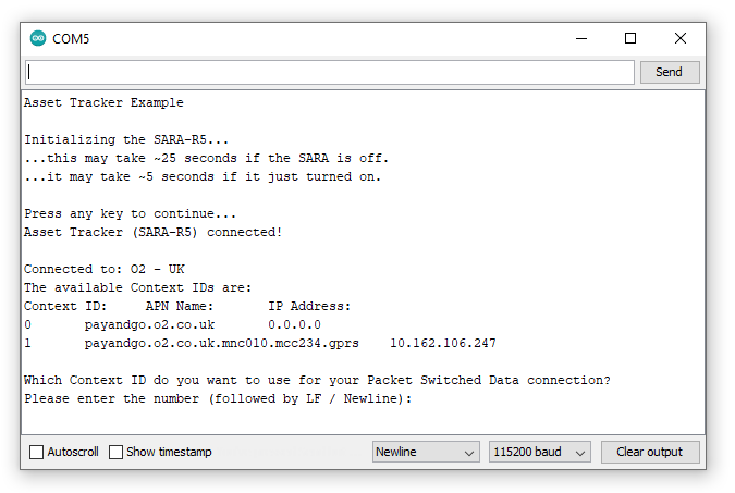
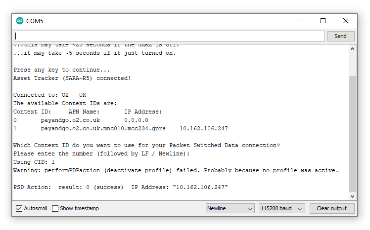
Example17 is an important example as it configures the “Context Identifier” for your mobile data connection. The SARA will read details of the data context from the network and SIM and you can confirm which one you want to use. The first context may be blank; select one that shows a sensible name and IP address for your service provider. In the screenshots below, we select option 1:
The code provides a warning that “deactivate profile failed”. We see this because the SARA needs to disconnect from a profile before it can connect to a new one, and in this case this failed because there was no profile active. Don’t worry about this warning, it is just there for information. The example shows that our connection was successful by displaying the Internet Protocol (IP) address the SARA has been allocated by the service operator.
Example 18: Ping
Example18 tests the SARA's data connection by performing one of the oldest and shortest data transfers going… A ping!
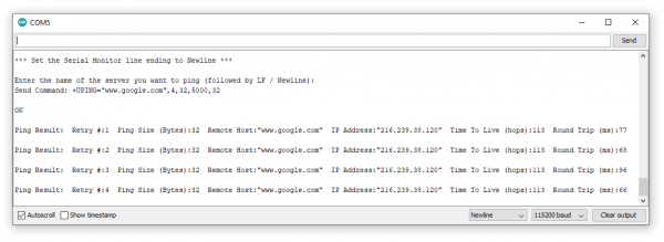
The code will ask for the name of the server you want to ping. www.google.com is a good choice, but www.sparkfun.com works too! If the ping is successful, you will see the time it took for the ping to do a round trip in milliseconds.
If the ping is not successful, one option to find out why is to uncomment the line which says:
language:c
assetTracker.enableDebugging(SERIAL_PORT); // Uncomment this line to enable helpful debug messages
This enables a bunch of helpful debug messages that print in the Serial Monitor or your terminal emulator window. After uncommenting the above line, upload the code again.
Look for any messages that include +UUPINGER:. That will give you the cause of the PING ERror. The SARA-R5 AT Command Reference contains the full list of Ping error codes in Appendix A.10.
For example, error 8 means that the SARA “Cannot resolve host” which is usually a sign that a Domain Name Server (DNS) is not available. Error 17 indicates “Packet Switched Data connection not established”. If you see errors like this, please make sure you ran examples 13, 14, 17 and 18 in order. Each builds on the previous example.
Example 19: ThingSpeak
Example19 demonstrates how to send data to ThingSpeak using HTTP POST or GET.
Prior to using this example you need to complete the following steps:
- Create a ThingSpeak User Account here
- Create a new Channel by selecting Channels --> My Channels --> New Channel
- Note the Write API Key and copy/paste it into
myWriteAPIKeyin the example code.
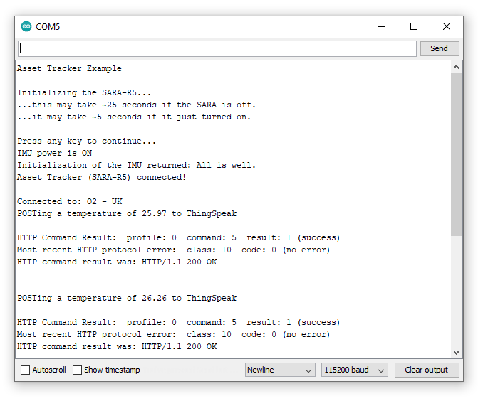
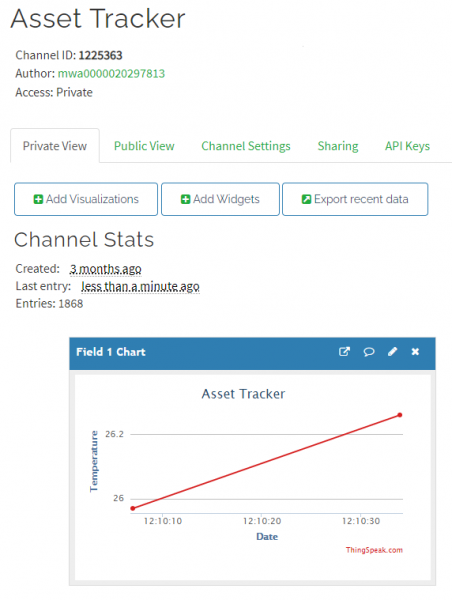
The example code reads the temperature from the Asset Tracker IMU and POSTs it to ThingSpeak. It will be added to your ThingSpeak channel as "Field 1".
If you open your serial monitor at 115200 baud the code prints out over serial the data sent to ThingSpeak:
Check your ThingSpeak channel and you should see data posted to it similar to the screenshot below:
Examples 20-22: Production Tests
Examples 20 - 22 are the ones we use using Asset Tracker production tests to check if the SARA’s I/O pins are connected correctly. We’ve included them as you might find them useful if you want to control the pins on the SARA. The examples use the SARA’s +UTEST mode to control the pins. Please consult the SARA-R5 AT Command Reference for further details.
