MicroMod Asset Tracker Carrier Board Hookup Guide
Introduction
The MicroMod Asset Tracker Carrier Board provides you with a toolkit to monitor and track the location of your assets. Do you want to know where your assets are at all times? Or maybe you just want an update if an asset is moved? If so, this is the product for you!
Built around the u-blox SARA-R510M8S module, the MicroMod Asset Tracker Carrier Board offers Secure Cloud LTE-M data communication for multi-regional use and has an integrated u-blox M8 GNSS receiver for accurate positioning information.
Want to be able to communicate directly with the SARA-R5 over USB-C, without needing a Processor Board? Or, want to upgrade the SARA firmware? The included Asset Tracker Update Tool lets you do just that. The Asset Tracker requires a Nano SIM for LTE-M connectivity. You can use the included Hologram eUICC SIM card or choose one from your preferred service provider if you prefer.
The Asset Tracker will work with any of our MicroMod Processor Boards, but because the asset tracker offers so many features and can be configured in different ways, some processor boards may be a better choice for your application than others. Please see “Choosing a Processor Board” below for more details.
The SARA-R5 supports many different forms of data communication from full TCP/IP sockets and packet switched data, through HTTP Get/Put/Post, FTP (the SARA has a built-in file system), Ping, to good old SMS text messaging!
The Asset Tracker has an integrated ICM-20948 Inertial Measurement Unit for 9-Degree Of Freedom orientation and movement detection. Want to send a message if your asset is moved? The asset tracker can do that! It also has a built-in digital microphone and so can send an alert as soon as a noise is detected too. Want to add a light sensor? The Qwiic connector will let you do that.
Want to use the Asset Tracker to log data during a journey or shipping? It has a built-in micro-SD card socket for data logging. Power options include both USB-C and LiPo battery (with built-in charging and battery fuel gauge), but you can provide power via a breakout pin too.
We’ve provided a full set of examples to get you up and running quickly and our SARA-R5 Arduino Library does all of the heavy lifting for you.
Required Materials
In addition to the MicroMod Asset Tracker Carrier Board, you’ll need a processor board to get started. Depending on which features of the SARA-R5 you want to use, some of our processor boards may be a better choice for your application. Please see “Choosing a Processor Board” below for more details.
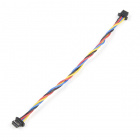
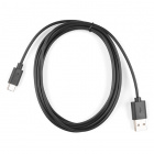
You'll also need a USB-C cable to connect the Carrier to your computer and if you want to add some Qwiic breakouts to your MicroMod project you'll want at least one Qwiic cable to connect it all together. Below are some options for both of those cables:
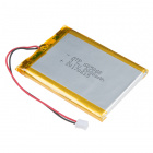
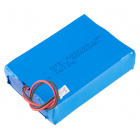
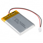
You can power the Asset Tracker via USB-C but for portable applications you'll need a single-cell LiPo battery too. Here are some examples:
Lithium Ion Battery - 1Ah
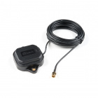
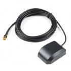
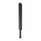
PRT-13813You'll also need LTE and GNSS antennas. There are many to choose from, but here are some recommendations:
Recommended Tools
You will need a screw driver to tighten the screw between the processor board and carrier board.
Suggested Reading
If you are not familiar with the MicroMod ecosystem, we recommend reading here for an overview. We recommend reading here for an overview if you decide to take advantage of the Qwiic connector.
 |
 |
| MicroMod Ecosystem | Qwiic Connect System |
Finally, if you aren't familiar with the following concepts you may want to check out a few of these tutorials before continuing.
Serial Communication
Installing an Arduino Library
Logic Levels
Getting Started with MicroMod
Hardware Overview
The MicroMod Asset Tracker has a lot going on so buckle up. In this section we'll cover the various components and hardware included on the Asset Tracker.
Common Components
Most SparkFun MicroMod Carriers will have some common components and all MicroMod Carriers will have the keyed M.2 MicroMod Connector to plug your processor into. The photo and list below outline some of the components you can expect on most SparkFun MicroMod Carriers.
- M.2 MicroMod Connector - This special keyed M.2 connector lets you install your MicroMod Processor of choice on your Asset Tracker Carrier Board.
- USB-C Connector - Connect to your computer to program your Processor and also can provide power to your MicroMod system.
- 3.3V Regulator - Provides a regulated 3.3V and sources up to 1A.
- Qwiic Connector - The standard Qwiic connector so you can add other Qwiic devices to your MicroMod system.
- Boot/Reset Buttons - Push buttons to enter Boot Mode on Processor boards and to Reset your MicroMod circuit.
- microSD Slot - Insert a microSD card for reading and writing data.
- RTC Battery - We've included a 3V Lithium Rechargeable Battery as a backup power source for the Processor Board Real Time Clock (if present).
u-blox SARA-R510M8S
The heart of the Asset Tracker is the SARA-R510M8S module from u-blox. This module does so much, it is difficult to know where to begin!
Designed to last an IoT lifetime, this module is 5G-ready with the u-blox UBX-R5 chipset. It has built-in end-to-end security with hardware-based root of trust inside a discrete secure element. It provides a full security suite with foundation, design and end-to-end security, as well as access control. The built-in u‑blox M8 GNSS receiver provides accurate and reliable positioning, always and everywhere. It is optimized for ultra-low power consumption and critical firmware updates can be delivered and services enabled via uFOTA (Firmware Over The Air). There. We told you it did a lot!
The SARA-R5 supports many different forms of data communication from full TCP/IP sockets and packet switched data, through HTTP Get/Put/Post, FTP (the SARA has a built-in file system), Ping, to good old SMS text messaging! The built-in GNSS receiver provides NMEA format data and our library looks after the parsing for you.
The connection between the SARA-R5 and the MicroMod Processor Board is serial (3.3V UART) but again, with this module being so clever, it can communicate over two serial interfaces at the same time. Want your LTE data on one interface and your GNSS data on a separate interface? It can do that too!
LTE and GNSS connections are via separate, robust SMA connectors. Switchable 3.3V power for an active antenna is available on the GNSS connector. The Asset Tracker includes a socket for a Nano SIM.
If you need to, you can manually turn the SARA off by pushing and holding the SARA On button. The SARA will disconnect from the network before going into low power sleep. Press the button briefly to turn the SARA back on again.
ICM-20948 IMU
The Asset Tracker carries the same ICM-20948 9-Degree Of Freedom Inertial Measurement Unit as OpenLog Artemis. It can provide fast accelerometer, gyro and magnetometer data and can be configured for “Wake On Motion” too. We have a WOM example ready to go. It has a built-in temperature sensor too.
Digital Microphone
Thieves are wily these days. When attempting to steal your asset, one of the first things they will do is cover or break the antenna (if they can see it). The built-in SPH0641 digital microphone can be used to send an alert as soon as the Asset Tracker hears the thieves coming!
Battery Charging and Monitoring Circuit
Since many applications for the Asset Tracker involve a battery-powered circuit, the board includes both the MCP73831 LiPo battery charger and the MAX17048 battery fuel gauge. The MCP7381 Single-cell charge management IC can deliver a charge current up to 500mA. The MAX17048 is a low-power I2C fuel gauge to monitor your battery's remaining charge.
Plated Through-Hole (PTH) Connections
GPIO PTHs
We've broken out dedicated PTHs for digital, analog, pulse width modulation (PWM), I2C and SPI along the sides of the Asset Tracker Carrier Board. You may also notice that we've included a ground rail next to the digital, analog and PWM pins.
Power PTHs
We've also provided PTHs for monitoring and accessing the following power circuits:
- VIN - The power rail fed by USB-C and/or the LiPo battery.
- 3.3V - The regulated 3.3V rail which feeds most of the components on the board. You can measure the 3.3V current draw using the MEAS pins (see below).
- VCCIO - This is the 1.8V rail generated by the SARA-R5. We use it to power the 1.8V to 3.3V level shifters for the UART and I2C connections.
- 1.8V - This is the 1.8V rail which powers the IMU. You can disable it by pulling the MicroMod G4 digital pin LOW.
- RST - Pull this low to reset the MicroMod Processor and the SARA-R5.
SARA-R5 PTHs
The following SARA-R5 I/O connections are also broken out to PTH headers:
- NI - This is the SARA's Network Indicator signal. It will be low (0V) when the network is available, and high (3.3V) when the network is not available.
- TP - This is the Timing Pulse (1PPS) signal and is connected to SARA GPIO6/TP. It will pulse low and high when the SARA is receiving a GNSS signal and the timing pulse has been enabled. Please see Example11 for more details.
- SARA USB D-/D+/DET - These PTHs provide access to the SARA's diagnostic USB port. This connection is only used to access the SARA's trace log. You cannot (currently) upgrade the SARA via this interface. Please consult the SARA R5 Integration Manual for more details.
- SARA I2C - These 3.3V (level-shifted) PTHs can be used to access the SARA's I2C bus. Some models of the SARA-R5 use I2C to communicate with an external GNSS module. As the SARA-R510M8S has GNSS built-in, it is unclear what you might want to use them for. But, we've been diligent and have broken them out anyway!
SWD Programming Pins
An unpopulated JTAG footprint is available for more advanced users who need breakpoint level debugging. Note that this is not populated so you will need a compatible header and compatible JTAG programmer to connect.
Solder Jumpers
On the rear of the board, you will find a large number of jumpers which you can use to connect and disconnect several of the connections between the SARA and the MicroMod Processor:
The tables below outline all of the jumpers on the Asset Tracker along with brief descriptions of their functionality.
| Jumper Name/Label | Description | Default State | Notes |
|---|---|---|---|
| G0 / SD CS | Ties the µSD Chip Enable to G0 | CLOSED | |
| G1 / SD PWR | Toggles 3.3V to control power the µSD card. | CLOSED | Open to isolate G1. µSD will default to always on. |
| G2 / LTE_PWR | Connects G2 to the SARA-R5 ON signal via a level-shifting circuit. | CLOSED | Allows G2 to function in the exact same way as the SARA On button. Cut the jumper to isolate G2 if required. |
| G3 / IMU PWR | When closed, G3 can be used to control power for the IMU via software. By default, IMU power is always on. | OPEN | On the ESP32 Processor G3 is linked directly to the processor's TX1 pin. Leave the G3 jumper OPEN if you are using the ESP32 Processor or else serial communication with the SARA will not work. |
| G4 / RI | When closed, connects G4 to the SARA-R5's Ring Indicator pin. | OPEN | On the ESP32 Processor, G4 is shared with the processor's RX1 pin. Similarly, G4 is shared with SPI CIPO on the RP2040 Processor. Leave this jumper OPEN if using either Processor to avoid serial communication errors with the SARA. |
| G5 / SARA INT | When closed, connects G5 with either the SARA-R5's Interrupt I/O pin or the SARA's GPIO3 I/O pin depending on the state of the EXT INT / GPIO3 dual jumper (covered below). | OPEN | On the RP2040 Processor, G5 is shared with SPI Chip Select line. Closing the jumper will interfere with the SPI bus on the RP2040 Processor. |
| G6 / SARA ON | When closed, this jumper allows G6 to monitor if the SARA power is on. | OPEN | This signal is different to the SARA On push-button. On the RP2040 Processor, G6 is shared with the SPI Clock line. Closing this jumper will interfere with the SPI bus on the RP2040 Processor. |
| G7 / DSR | When closed, connects G7 to the SARA's DSR signal. | OPEN | On the RP2040 Processor, G7 is shared with the SPI COPI line. Leave this jumper open to avoid interfering with the SPI bus on this processor. |
| PDM DAT | Connects the data signal from on-board microphone to AUD_LRCLK (MicroMod Pad 52). | CLOSED | On the RP2040 Processor, AUD_LRCLK is shared with CTS1. Open this jumper to use the CTS connection on the SARA. |
| PDM CLK | Connects the clock signal from the on-board microphone to AUD_BCLK (MicroMod Pad 50). | CLOSED | On the RP2040 Processor, AUD_BCLK is shared with RTS1. Open this jumper to use the RTS connection on the SARA. |
| I2C | A dual jumper that ties SDA & SCL on the primary I2C/Qwiic bus to 3.3V via a pair of 2.2kΩ resistors. | CLOSED | Open both jumpers to disconnect the pull-ups. |
| SARA I2C | A dual jumper that ties the SARA's SDA and SCL lines to 3.3V via a pair of 2.2kΩ | CLOSED | Open both jumpers to disable the pull-ups. |
| CIPO | Ties SPI CIPO/SDI to 3.3V via a 2.2kΩ resistor. | CLOSED | Open to disconnect the pull-up. Opening this jumper may be advantageous for very low power applications where Processors like the Artemis have internal pull-ups which can be used instead. |
| EXT INT / GPIO3 | A dual jumper used to select which signal is connected to MicroMod G5. | SEE NOTE | By default, this jumper is set so if the G5 / SARA INT jumper is closed, G5 is connected to the SARA EXT INT I/O pin. Switch this jumper to the opposite side to connect G5 to the SARA GPIO3 pin. |
| DSR | A dual jumper used to control the direction of DSR from input to output . | SEE NOTE | By default, this jumper sets DSR as an input. Switching it sets DSR as an output so users can use dual-UART communication modes on the SARA. |
| MEAS | Allows users to measure the current draw from the 3.3V power rail. | CLOSED | Open this jumper and complete the circuit using a digital multimeter to measure current draw on the 3.3V power rail. |
| VIN/3 | Completes the VIN/3 voltage divider circuit. | CLOSED | Open the jumper to disable the VIN/3 voltage divider circuit. Disabling this can be useful in very low power applications to reduce total current draw. |
| 3V3 (LED) | Connects the anode of the 3.3V LED to 3.3V via a 1kΩ resistor. | CLOSED | Open the jumper to disable the 3.3V LED to reduce total current draw of the MicroMod circuit. |
| VIN (LED) | Connects the anode of the VIN LED to VIN (5V if powered by USB, 3.7V nominal if powered by LiPo battery) via a 4.7kΩ resistor. | CLOSED | Open the jumper to disable the VIN LED to reduce the total current draw of the MicroMod circuit. |
| ICM_INT | Connects the ICM IMU Interrupt pin to the primary I2C Interrupt pin (I2C_INT) on the MicroMod connector. | CLOSED | Open the jumper to isolate the MicroMod I2C_INT pin from the ICM-20948. On the RP2040 Processor, I2C_INT is shared with TX2. You may need to open this jumper to use the DTR handshake signal. |
| Jumper Name/Label | Description | Default State | Notes |
|---|---|---|---|
| V USB | Connects VUSB_DET on the SARA's diganostic (trace log) USB port to V_USB (5V | OPEN | Important! You must not have a Processor installed to use the diagnostic USB port. |
| USB D+ | Connects USB_D+ on the SARA's diagnostic (trace log) USB port to USB_D+ on the USB-C connector. | OPEN | Important! You must not have a Processor installed to use the diagnostic USB port. |
| USB_D- | Connects USB_D- on the SARA's diagnostic (trace log) USB port to USB_D- on the USB-C connector. | OPEN | Important! You must not have a Processor installed to use the diagnostic USB port. |
| VE | When closed, allows the Processor to disable the main 3.3V regulator via the 3.3V_EN pin. | OPEN | Recommended only for very low power applications. The Processor can draw power from the RTC battery while the voltage regulator is disabled. |
| BYP | Bypasses the 6V/2A fuse and nets VIN and V_USB together. | OPEN | The "penny-in-the-fuse" jumper. Close only if you know what you are doing! |
MicroMod Pinout
Wondering what the pins are that are broken out on the MicroMod Asset Tracker Carrier Board? The tables below outline the Asset Tracker pinout as well as the general MicroMod pinout. Remember to compare the pins against your Processor Board to determine which pins are available.
| AUDIO | UART | GPIO/BUS | I2C | SDIO | SPI0 | Dedicated |
| M.2 Connector Pin# | MicroMod Pin Name | Asset Tracker Connection | Description |
|---|---|---|---|
| 1 | GND | GND | Ground plane. |
| 2 | 3.3V | 3.3V | Regulated 3.3V via USB-C. |
| 3 | USB_D+ | Passthrough | USB D+ connection for Processor Board. |
| 4 | 3.3V_EN | 3.3V Enable | Voltage regulator enable input. |
| 5 | USB_D- | Passthrough | USB D- connection for Processor Board. |
| 6 | RESET | RESET Button | Connected to RESET Button. Reset is active LOW |
| 9 | USB_VIN | VIN | Input voltage from USB. |
| 10 | D0 | SPI PTH CS/D0 PTH | SPI Chip Select for SPI PTH Header. D0 also broken out for I/O PTHs |
| 11 | BOOT | BOOT Button | Connected to BOOT Button. Boot is active LOW. |
| 12 | I2C_SDA | I2C_SDA | I2C data for Fuel Gauge & Qwiic connector |
| 13 | UART_RTS1 | SARA RTS_I | UART Request to Send for SARA |
| 14 | I2C_SCL | I2C_SCL | I2C clock for Fuel Gauge & Qwiic connector |
| 15 | UART_CTS1 | SARA CTS_O | UART Clear to Send for SARA |
| 16 | I2C_INT# | IMU INT | IMU Interrupt pin |
| 17 | UART_RX1 | SARA TXD_O | SARA UART Data Iutput |
| 18 | D1 | D1 | General digital I/O PTH |
| 19 | UART_TX1 | SARA TXD_I | SARA UART Data Output |
| 20 | UART_RX2 | SARA DCD_O/RXD2_O | SARA UART Data Carrier Detect / AUX UART Data Output |
| 21 | SWDCK | SWDCK | Serial Wire Debug Clock |
| 22 | UART_TX2 | SARA DTR_I/TXD2_I | SARA UART Data Terminal Ready / AUX UART Data Input |
| 23 | SWDIO | SWDIO | Serial Wire Debug I/O |
| 32 | PWM0 | PWM0 | PWM0 PTH |
| 34 | A0 | A0 | A0 PTH (Input Only) |
| 34 | A1 | A1 | A1 PTH (Input Only) |
| 40 | G0/BUS0 | SD CS | General purpose pin configured for Chip Select on µSD. |
| 42 | G1/BUS1 | microSD_PWR | General purpose pin configured for µSD Power Enable |
| 44 | G2/BUS2 | LTE_PWR_ON | General purpose pin configured for turning SARA on/off |
| 46 | G3/BUS3 | ICM_PWR | General purpose pin configured for controlling IMU power |
| 48 | G4/BUS4 | SARA RI_O/CTS2_O | SARA UART Ring Indicator / AUX UART Clear to Send |
| 49 | BATT_VIN/3 | VIN/3 | Divided input voltage for monitoring power supply. |
| 50 | AUD_BCLK | I2S_SCK/PDM_CLK | Microphone PDM clock signal |
| 51 | I2C_SDA1 | SARA I2C SDA | SARA I2C data signal |
| 52 | AUD_LRCLK | I2S_WS/PDM_DAT | Microphone PDM data signal |
| 53 | I2C_SCL1 | SARA I2C SCL | SARA I2C clock signal |
| 55 | SPI_CS# | ICM_CS | Chip select for IMU level shifting IC |
| 57 | SPI_SCK | SPI_SCK | SPI Clock |
| 59 | SPI_COPI | SPI_SDO | SPI controller out/peripheral in |
| 61 | SPI_CIPO | SPI_SDO | SPI controller in/peripheral out |
| 69 | G7/BUS7 | SARA DSR_O/RTS2_I | SARA UART Data Set Ready / AUX UART Request to Send |
| 71 | G6/BUS6 | SARA_ON | General purpose pin conifgured to monitor power for SARA |
| 72 | RTC_3V | RTC_3V | 3V output for backup battery charging. |
| 73 | G5/BUS5 | SARA_INT | General purpose pin configured for SARA Interrupt I/O pin |
| 74 | 3.3V | 3.3V | 3.3V output from voltage regulator |
| Function | Bottom Pin |
Top Pin |
Function | ||||||
|---|---|---|---|---|---|---|---|---|---|
| (Not Connected) | 75 | GND | |||||||
| 3.3V | 74 | 73 | G5 / BUS5 | ||||||
| RTC_3V_BATT | 72 | 71 | G6 / BUS6 | ||||||
| SPI_CS1# | SDIO_DATA3 (I/O) | 70 | 69 | G7 / BUS7 | |||||
| SDIO_DATA2 (I/O) | 68 | 67 | G8 | ||||||
| SDIO_DATA1 (I/O) | 66 | 65 | G9 | ADC_D- | CAM_HSYNC | ||||
| SPI_CIPO1 | SDIO_DATA0 (I/O) | 64 | 63 | G10 | ADC_D+ | CAM_VSYNC | |||
| SPI COPI1 | SDIO_CMD (I/O) | 62 | 61 | SPI_CIPO (I) | |||||
| SPI SCK1 | SDIO_SCK (O) | 60 | 59 | SPI_COPI (O) | LED_DAT | ||||
| AUD_MCLK (O) | 58 | 57 | SPI_SCK (O) | LED_CLK | |||||
| CAM_MCLK | PCM_OUT | I2S_OUT | AUD_OUT | 56 | 55 | SPI_CS# | |||
| CAM_PCLK | PCM_IN | I2S_IN | AUD_IN | 54 | 53 | I2C_SCL1 (I/O) | |||
| PDM_DATA | PCM_SYNC | I2S_WS | AUD_LRCLK | 52 | 51 | I2C_SDA1 (I/O) | |||
| PDM_CLK | PCM_CLK | I2S_SCK | AUD_BCLK | 50 | 49 | BATT_VIN / 3 (I - ADC) (0 to 3.3V) | |||
| G4 / BUS4 | 48 | 47 | PWM1 | ||||||
| G3 / BUS3 | 46 | 45 | GND | ||||||
| G2 / BUS2 | 44 | 43 | CAN_TX | ||||||
| G1 / BUS1 | 42 | 41 | CAN_RX | ||||||
| G0 / BUS0 | 40 | 39 | GND | ||||||
| A1 | 38 | 37 | USBHOST_D- | ||||||
| GND | 36 | 35 | USBHOST_D+ | ||||||
| A0 | 34 | 33 | GND | ||||||
| PWM0 | 32 | 31 | Module Key | ||||||
| Module Key | 30 | 29 | Module Key | ||||||
| Module Key | 28 | 27 | Module Key | ||||||
| Module Key | 26 | 25 | Module Key | ||||||
| Module Key | 24 | 23 | SWDIO | ||||||
| UART_TX2 (O) | 22 | 21 | SWDCK | ||||||
| UART_RX2 (I) | 20 | 19 | UART_RX1 (I) | ||||||
| CAM_TRIG | D1 | 18 | 17 | UART_TX1 (0) | |||||
| I2C_INT# | 16 | 15 | UART_CTS1 (I) | ||||||
| I2C_SCL (I/0) | 14 | 13 | UART_RTS1 (O) | ||||||
| I2C_SDA (I/0) | 12 | 11 | BOOT (I - Open Drain) | ||||||
| D0 | 10 | 9 | USB_VIN | ||||||
| SWO | G11 | 8 | 7 | GND | |||||
| RESET# (I - Open Drain) | 6 | 5 | USB_D- | ||||||
| 3.3V_EN | 4 | 3 | USB_D+ | ||||||
| 3.3V | 2 | 1 | GND | ||||||
| Signal Group | Signal | I/O | Description | Voltage | Power | 3.3V | I | 3.3V Source | 3.3V |
|---|---|---|---|---|
| GND | Return current path | 0V | ||
| USB_VIN | I | USB VIN compliant to USB 2.0 specification. Connect to pins on processor board that require 5V for USB functionality | 4.8-5.2V | |
| RTC_3V_BATT | I | 3V provided by external coin cell or mini battery. Max draw=100μA. Connect to pins maintaining an RTC during power loss. Can be left NC. | 3V | |
| 3.3V_EN | O | Controls the carrier board's main voltage regulator. Voltage above 1V will enable 3.3V power path. | 3.3V | |
| BATT_VIN/3 | I | Carrier board raw voltage over 3. 1/3 resistor divider is implemented on carrier board. Amplify the analog signal as needed for full 0-3.3V range | 3.3V | |
| Reset | Reset | I | Input to processor. Open drain with pullup on processor board. Pulling low resets processor. | 3.3V |
| Boot | I | Input to processor. Open drain with pullup on processor board. Pulling low puts processor into special boot mode. Can be left NC. | 3.3V | |
| USB | USB_D± | I/O | USB Data ±. Differential serial data interface compliant to USB 2.0 specification. If UART is required for programming, USB± must be routed to a USB-to-serial conversion IC on the processor board. | |
| USB Host | USBHOST_D± | I/O | For processors that support USB Host Mode. USB Data±. Differential serial data interface compliant to USB 2.0 specification. Can be left NC. | |
| CAN | CAN_RX | I | CAN Bus receive data. | 3.3V |
| CAN_TX | O | CAN Bus transmit data. | 3.3V | |
| UART | UART_RX1 | I | UART receive data. | 3.3V |
| UART_TX1 | O | UART transmit data. | 3.3V | |
| UART_RTS1 | O | UART request to send. | 3.3V | |
| UART_CTS1 | I | UART clear to send. | 3.3V | |
| UART_RX2 | I | 2nd UART receive data. | 3.3V | |
| UART_TX2 | O | 2nd UART transmit data. | 3.3V | |
| I2C | I2C_SCL | I/O | I2C clock. Open drain with pullup on carrier board. | 3.3V |
| I2C_SDA | I/O | I2C data. Open drain with pullup on carrier board | 3.3V | |
| I2C_INT# | I | Interrupt notification from carrier board to processor. Open drain with pullup on carrier board. Active LOW | 3.3V | |
| I2C_SCL1 | I/O | 2nd I2C clock. Open drain with pullup on carrier board. | 3.3V | |
| I2C_SDA1 | I/O | 2nd I2C data. Open drain with pullup on carrier board. | 3.3V | |
| SPI | SPI_COPI | O | SPI Controller Output/Peripheral Input. | 3.3V |
| SPI_CIPO | I | SPI Controller Input/Peripheral Output. | 3.3V | |
| SPI_SCK | O | SPI Clock. | 3.3V | |
| SPI_CS# | O | SPI Chip Select. Active LOW. Can be routed to GPIO if hardware CS is unused. | 3.3V | |
| SPI/SDIO | SPI_SCK1/SDIO_CLK | O | 2nd SPI Clock. Secondary use is SDIO Clock. | 3.3V |
| SPI_COPI1/SDIO_CMD | I/O | 2nd SPI Controller Output/Peripheral Input. Secondary use is SDIO command interface. | 3.3V | |
| SPI_CIPO1/SDIO_DATA0 | I/O | 2nd SPI Peripheral Input/Controller Output. Secondary use is SDIO data exchange bit 0. | 3.3V | |
| SDIO_DATA1 | I/O | SDIO data exchange bit 1. | 3.3V | |
| SDIO_DATA2 | I/O | SDIO data exchange bit 2. | 3.3V | |
| SPI_CS1/SDIO_DATA3 | I/O | 2nd SPI Chip Select. Secondary use is SDIO data exchange bit 3. | 3.3V | |
| Audio | AUD_MCLK | O | Audio master clock. | 3.3V |
| AUD_OUT/PCM_OUT/I2S_OUT/CAM_MCLK | O | Audio data output. PCM synchronous data output. I2S serial data out. Camera master clock. | 3.3V | |
| AUD_IN/PCM_IN/I2S_IN/CAM_PCLK | I | Audio data input. PCM syncrhonous data input. I2S serial data in. Camera periphperal clock. | 3.3V | |
| AUD_LRCLK/PCM_SYNC/I2S_WS/PDM_DATA | I/O | Audio left/right clock. PCM syncrhonous data SYNC. I2S word select. PDM data. | 3.3V | |
| AUD_BCLK/PCM_CLK/I2S_CLK/PDM_CLK | O | Audio bit clock. PCM clock. I2S continuous serial clock. PDM clock. | 3.3V | |
| SWD | SWDIO | I/O | Serial Wire Debug I/O. Connect if processor board supports SWD. Can be left NC. | 3.3V |
| SWDCK | I | Serial Wire Debug clock. Connect if processor board supports SWD. Can be left NC. | 3.3V | |
| ADC | A0 | I | Analog to digital converter 0. Amplify the analog signal as needed to enable full 0-3.3V range. | 3.3V |
| A1 | I | Analog to digital converter 1. Amplify the analog signal as needed to enable full 0-3.3V range. | 3.3V | |
| PWM | PWM0 | O | Pulse width modulated output 0. | 3.3V |
| PWM1 | O | Pulse width modulated output 1. | 3.3V | |
| Digital | D0 | I/O | General digital input/output pin. | 3.3V |
| D1/CAM_TRIG | I/O | General digital input/output pin. Camera trigger. | 3.3V | |
| General/Bus | G0/BUS0 | I/O | General purpose pins. Any unused processor pins should be assigned to Gx with ADC + PWM capable pins given priority (0, 1, 2, etc.) positions. The intent is to guarantee PWM, ADC and Digital Pin functionality on respective ADC/PWM/Digital pins. Gx pins do not guarantee ADC/PWM function. Alternative use is pins can support a fast read/write 8-bit or 4-bit wide bus. | 3.3V |
| G1/BUS1 | I/O | 3.3V | ||
| G2/BUS2 | I/O | 3.3V | ||
| G3/BUS3 | I/O | 3.3V | ||
| G4/BUS4 | I/O | 3.3V | ||
| G5/BUS5 | I/O | 3.3V | ||
| G6/BUS6 | I/O | 3.3V | ||
| G7/BUS7 | I/O | 3.3V | ||
| G8 | I/O | General purpose pin | 3.3V | |
| G9/ADC_D-/CAM_HSYNC | I/O | Differential ADC input if available. Camera horizontal sync. | 3.3V | |
| G10/ADC_D+/CAM_VSYNC | I/O | Differential ADC input if available. Camera vertical sync. | 3.3V | |
| G11/SWO | I/O | General purpose pin. Serial Wire Output | 3.3V |
Board Dimensions
The Asset Tracker Carrier Board measures 3.0 inches by 3.0 inches (76.2mm x 76.2mm) and has four mounting holes that fit a 4-40 screw.
Choosing a Processor Board
As you can see from the Jumpers section above, there are some things to consider when choosing a MicroMod Processor Board to go with your Asset Tracker.
The MicroMod M.2 connector pinout is very comprehensive and some of the processor chips on our MicroMod Processor Boards just don't have enough I/O pins to let us allocate one to every M.2 pin. So, on those boards we share the pins. For example, on the ESP32 Processor Board, you will see that the UART TX1 pin is shared with the G3 I/O pin and the AUD_OUT pin. We do that so that you can use that pin for TX1 or G3 or AUD_OUT. And for most users and most Carrier Boards, that's perfectly fine. However, since the SARA-R5 has so many pins that we need to connect to, the sharing of TX1 and G3 causes a small problem. We need TX1 to communicate with the SARA, and G3 would normally be used to enable power for the ICM-20948 IMU. We get round that by including a normally-open split pad jumper on G3 and making the IMU power circuit default to on. Simple!
So, you can use any SparkFun MicroMod Processor in the Asset Tracker, but if you need complete access to all of the pins then here are the restrictions:
ESP32 Processor
TX1 is shared with G3. This means you cannot close the G3 split pad to enable control of the IMU Power. The IMU power will need to be always on.
RX1 is shared with G4. This means you cannot close the G4 split pad to access the SARA Ring Indicator / Clear To Send 2 pin.
AUD_LRCLK is shared with G1. G1 controls the micro-SD power and AUD_LRCLK is connected to the digital microphone. If you want to use the microphone, you will need to open the G1 split pad jumper. The micro-SD power will default to on.
AUD_BCLK is shared with G2. G2 can be used to turn the SARA-R5 on/off and AUD_BCLK is connected to the digital microphone. If you want to use the microphone, you will need to open the G2 jumper. You won’t then be able to have the processor turn the SARA on and off. The SARA always powers on automatically when power is connected, so no worries there, and the SARA On button is there if you need it.
Artemis Processor
The Artemis Processor does not support the M.2 TX2 and RX2 pins. This means you cannot use the Artemis to talk to the SARA using any of the dual-UART variants (called variants 2, 3 and 4 in the SARA-R5 System Integration Manual). This means you cannot, for example, use UART 1 for your LTE traffic and UART 2 for your GNSS data. That's all. You can do everything over a single UART anyway.
nRF5280 Processor
The nRF52840 Processor Board supports all of the pins used by the Asset Tracker. There are no restrictions for this Processor Board.
SAMD51 Processor
The SAMD51 Processor Board does not support RTS1 and CTS1 and so you will not be able to perform hardware handshaking when using the UART. Serial buffers are so large these days that you probably won’t even notice this restriction, but it is something to be aware of.
RP2040 Processor
AUD_LRCLK is shared with CTS1. This means that if you want to use hardware handshaking for the UART communication, you won’t be able to use the digital microphone.
Likewise AUD_BCLK is shared with RTS1, again preventing you from using the microphone and hardware handshaking at the same time.
I2C_INT is shared with TX2. This means that you cannot use the ICM-20948 IMU interrupt and SARA DTR / TXD2 simultaneously. You can open the ICM_INT split pad to isolate the IMU interrupt signal.
G4, G5, G6 and G7 are shared with the SPI connections SPI_SCK, SPI_COPI, SPI_CIPO and SPI_CS. This should not be an issue for you, but it does mean you cannot close the G4-G7 jumpers to enable access to: SARA_RI, SARA_INT, SARA is On, and SARA_DSR.
STM32 Processor
The STM32 Processor Board does not support RTS1 and CTS1 and so you will not be able to perform hardware handshaking when using the UART. Serial buffers are so large these days that you probably won’t even notice this restriction, but it is something to be aware of.
The STM32 Processor Board does not support the M.2 TX2 and RX2 pins. This means you cannot use the STM32 to talk to the SARA using any of the dual-UART variants (called variants 2, 3 and 4 in the SARA-R5 System Integration Manual). You cannot, for example, use UART 1 for your LTE traffic and UART 2 for your GNSS data.
G7 is not supported on the STM32 Processor Board. This should not be an issue for you, but it does mean you cannot access the SARA is On signal.
Hardware Assembly
Now that we are familiar with the hardware on the Asset Tracker Carrier Board, it's time to assemble it with your chosen MicroMod Processor and get it connected to your computer.
Inserting Your Processor
With the M.2 MicroMod connector, connecting your processor board is a breeze. Simply match up the key on your processor's beveled edge connector to the key on the M.2 connector. At a 45° angle, insert the processor board to the M.2 connector. The processor board will stick up at an angle as seen here:
Once the board is in the socket, gently press the Processor down, grab the set screw and tighten it with a Phillip's head screwdriver:
With the Processor secure, your assembled MicroMod Asset Tracker system should look similar to the image below!
Connecting Everything Up
Now is a good time to insert the Nano SIM from your service provider. Make sure the orientation matches the symbol on the PCB; the edge with the trimmed corner is inserted first.
The LTE and GNSS connections simply screw on to the appropriate SMA connectors. Make sure you check the labeling on the board and connect them the right way round. (LTE is on the Left.)
With your processor inserted and secured it's time to connect your MicroMod Asset Tracker Carrier Board to your computer using the USB-C connector. Depending on which processor you choose and which drivers you already have installed, you may need to install drivers for your board. Refer to your Processor's Hookup Guide for detailed instructions on how to install them.
Software Setup
The Asset Tracker examples will run on any SparkFun MicroMod Processor Board (PB) but each PB has a slightly different sequence to follow when uploading and running code. For example, some require a press of the Boot button and others do not. Head over to our MicroMod Processor Boards landing page, find your Processor, and read through its tutorial for help installing your board definition and how to upload the code.
We have prepared a complete set of examples showing you how to use all of the features on the Asset Tracker. However, the examples need access to several Arduino Libraries before they will run correctly and so you need to install those too.
Installing the MicroMod Asset Tracker Carrier Board Examples
The Asset Tracker examples live on GitHub in the Asset Tracker repository and you will find them in the Examples folder. You can download the complete repository from GitHub as a single .ZIP file by clicking the button below:
Unzip the .ZIP file and copy all 22 examples to a suitable folder on your computer. We recommend putting them in your Arduino folder.
You will see that each example comprises three files. E.g for Example1:
- AssetTracker_Example1_Blink.ino is the actual example code
- AssetTrackerPins.h contains the pin definitions to allow each Processor to work correctly with the Asset Tracker
- AssetTrackerPins.ino contains useful ‘housekeeping’ functions that do things like turn on the SD or IMU power. They are in a separate file to make them easier to update when we add new processor boards and to avoid cluttering up the main example code.
When it is time to open and try Example1 select the AssetTracker_Example1_Blink.ino file first. The other two will open automatically as they are in the same folder.
SparkFun u-blox SARA-R5 Arduino Library
The SparkFun u-blox SARA-R5 Arduino Library lives on GitHub too and you can either install it using the Arduino Library Manager, or you can install it manually.
If you want to install the library using the Arduino Library Manager, then search for ‘SparkFun u-blox SARA-R5’.
Alternatively, you can download a .ZIP of the library by clicking the button below:
Additional Libraries
Once you have the u-blox SARA-R5 library installed, most (but not all) of the examples will work correctly. To allow the full set to run, you also need to install the following libraries:
- SparkFun ICM-20948 IMU Arduino Library
- SparkFun MAX1704x Fuel Gauge Arduino Library
- SparkFun Qwiic Power Switch Arduino Library
- SparkFun Micro OLED Arduino Library
- Bill Greiman' SdFat Library
You can install them using the Arduino Library manager by searching for their respective names. Alternatively, you can download the .ZIP for each of them by clicking the buttons below:
Arduino Examples
Once you have the MicroMod Asset Tracker Carrier Board examples and all of the required libraries installed, it is finally time to run your first example!
Example 1: Blink
Baby steps… Example1 checks that you can communicate with the MicroMod Processor Board, compile and upload code successfully.
Navigate to the location the Asset Tracker Examples repository downloaded to and open the Examples folder. In that folder you'll find all the examples. Navigate to Example1 and open the file called AssetTracker_Example1_Blink.ino in the Arduino IDE or copy the code below into a blank sketch, select your Board and Port and click "Upload".
language:c
#include "AssetTrackerPins.h" // Include the Asset Tracker pin and port definitions

#define SERIAL_PORT Serial // This is the console serial port - change this if required

#include <SparkFun_u-blox_SARA-R5_Arduino_Library.h> //Click here to get the library: http://librarymanager/All#SparkFun_u-blox_SARA-R5_Arduino_Library

// Create a SARA_R5 object to use throughout the sketch. Pass it the power pin number.
SARA_R5 assetTracker(SARA_PWR);

void setup()
{
  initializeAssetTrackerPins(); // Initialize the pins and ports (defined in AssetTrackerPins.ino)
}

void loop()
{
  digitalWrite(LED_BUILTIN, !digitalRead(LED_BUILTIN)); // Flash the STAT LED at 0.5Hz (Read-Invert-Write)
  delay(1000);
}
All Example1 does is blink the STAT LED on the Processor Board. That's all it does. Yes, really. But it proves that you have the correct Processor Board selected and that code compilation and upload works. The good stuff comes in the following examples.
Example 2: IMU
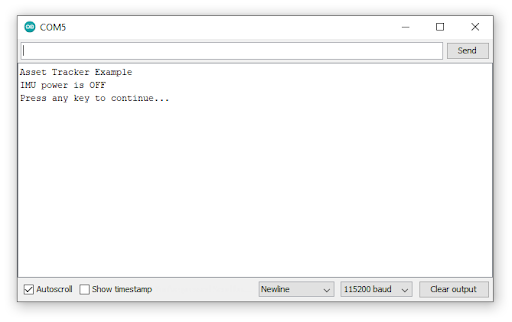
Example2 demonstrates how to get readings from the ICM-20948 Inertial Measurement Unit on the Asset Tracker. Open AssetTracker_Example2_IMU.ino and upload to the Processor Board. Now open the Serial Monitor or a terminal emulator and connect to the Processor Board at 115200 Baud. If all is well, you should see the following:
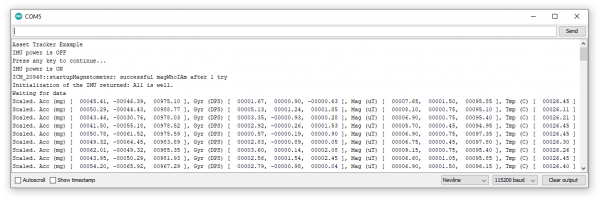
Click Send or hit Enter and you should then see the following, followed by lots of lovely IMU data scrolling up the screen:
The things to look out for are a 980 milli-g Acceleration in Z - if your board is horizontal. That's gravity. You will also see a reading of the Earth's magnetic field on one or more of the Magnetometer (Compass) axes, but the value will depend on your local Angle Of Magnetic Declination and Inclination. (Strange but true: the strongest magnetic field points downward into the ground in many places.)
Example 3: µSD Card
Example3 uses Bill Greiman's SdFat library to print a directory of all the files on your microSD card.
The usual restrictions apply: we recommend disconnecting the power to your Asset Tracker before removing or inserting the µSD card. Removing the card while powered can cause data corruption.
Example 4: MAX17048 Fuel Gauge
Example4 demonstrates how to use the MAX17048 Fuel Gauge to read the battery charge status.
Example 5: Qwiic
Example5 demonstrates how to use the Qwiic bus to talk to an external sensor attached to the Qwiic connector. The example assumes that you have a Qwiic Power Switch attached, but you can adapt the code to use whichever Qwiic board you have available. The Qwiic I2C bus is called Wire on the Asset Tracker.
Example 6: I/O Pins
Example6 demonstrates how to configure the D0, D1, A0, A1, PWM0 and PWM1 Input / Output pins.
Example 7: GNSS Antenna Power
Example7 is where we communicate with the SARA-R5 for the first time. The power for the active GNSS antenna is controlled by the SARA GPIO2 pin. When the SARA is on and GPIO2 is high, the 3.3V antenna power is enabled. We need to instruct the SARA to enable GPIO2 and set it high via the UART interface.
The example code calls enableGNSSAntennaPower(); and disableGNSSAntennaPower(); which do the heavy lifting for you. Those functions are defined in AssetTrackerPins.in and in turn call the SARA-R5 library:
language:c
assetTracker.setGpioMode(assetTracker.GPIO2, assetTracker.GPIO_OUTPUT, 1); // Enable
and
language:c
assetTracker.setGpioMode(assetTracker.GPIO2, assetTracker.GPIO_OUTPUT, 0); // Disable
There is no indicator LED to tell you if the antenna power is on. You can, if you wish, use a digital multimeter to probe carefully on the center pin of the GNSS SMA connector. You will see voltage toggling between 3.3V and 0V.
This example demonstrates that serial communication is taking place between the Processor Board and the SARA-R5.
Example 8: External SPI
Example8 shows how to use the SPI Breakout Plated-Through Holes (PTHs) on the left edge of the board. The example assumes you have a SparkFun Micro OLED Display connected, but you can adapt the code to talk to whichever SPI board you have available. The SPI port is called SPI on the Asset Tracker.
Example 9: VIN
Example9 demonstrates how to read the VIN bus voltage using the resistor divider on the Asset Tracker. The function readVIN() in AssetTrackerPins.ino automatically converts the Analog To Digital Converter result into voltage correctly for the different Processor Boards.
Example 10: IMU Wake-On-Motion
Example10 demonstrates how the ICM-20948 IMU can be configured to detect motion or an impact. This example could be a key part of your final asset-tracking code.
Example 11: GNSS GPRMC
Example11 demonstrates how to read the Asset Tracker’s location using the u-blox M8 GNSS receiver built into the SARA-R5. The GNSS generates an NMEA GPRMC data stream and our SARA-R5 library does the heavy lifting for you, extracting the latitude and longitude etc. as numbers.
Example 12: Identification
Example12 is the first example which communicates with the LTE part of SARA-R5. The example reads data from the SARA including its ID, firmware version, serial number, IMEI and subscriber number. The subscriber number - if present - comes from the SIM. This example demonstrates that the SIM is inserted correctly.
Example 13: Network Information
Example13 is the first example which checks that the SARA is receiving an LTE signal. The code prints the received signal strength, registration status and data “context ID”. The SARA reads your operator details from the SIM and uses those when registering on the network.
It is important that you run examples 13, 14 and 17 in order as each plays a role in making sure the SARA's data connection is configured correctly.
Example 14: Register Operator
Example14 shows if you are already connected to a network and gives you the opportunity to register on a different network (if one is available and if your SIM supports this). You can use this example to list all of the LTE operators the SARA can detect, but you will only be able to connect to networks supported by your SIM.
Example 15: Receive SMS
For many applications, good old Short Message Service text messaging is a good solution. Example15 demonstrates how to read and print any existing text messages in the SARA's memory. The code will then wait for a new message to arrive and will print it when it does.
Incoming messages are automatically marked as read once they have been printed by the code. You can force the code to print all the messages in memory by commenting the line which says:
language:c
if (unread == "REC UNREAD") // Only print new (previously-unread) messages.
Example 16: Send SMS
Example16 demonstrates how to send an SMS message to another phone or Asset Tracker. The code will ask for the destination number, followed by the message. If you are using the Arduino IDE Serial Monitor, you can type these into the text box at the top of the window and then click Send or press Enter. If you are using a terminal emulator, type the number and then press Enter (or add a newline / line feed character (“\n” or 0x0A)) to end the message.
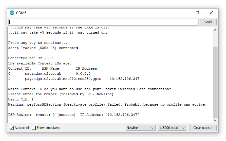
Example 17: Packet Switched Data
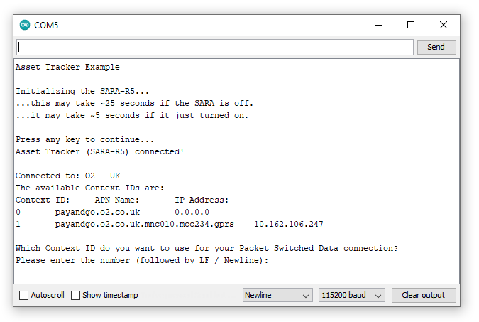
Example17 is an important example as it configures the “Context Identifier” for your mobile data connection. The SARA will read details of the data context from the network and SIM and you can confirm which one you want to use. The first context may be blank; select one that shows a sensible name and IP address for your service provider. In the screenshots below, we select option 1:
The code provides a warning that “deactivate profile failed”. We see this because the SARA needs to disconnect from a profile before it can connect to a new one, and in this case this failed because there was no profile active. Don’t worry about this warning, it is just there for information. The example shows that our connection was successful by displaying the Internet Protocol (IP) address the SARA has been allocated by the service operator.
Example 18: Ping
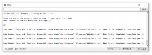
Example18 tests the SARA's data connection by performing one of the oldest and shortest data transfers going… A ping!
The code will ask for the name of the server you want to ping. www.google.com is a good choice, but www.sparkfun.com works too! If the ping is successful, you will see the time it took for the ping to do a round trip in milliseconds.
If the ping is not successful, one option to find out why is to uncomment the line which says:
language:c
assetTracker.enableDebugging(SERIAL_PORT); // Uncomment this line to enable helpful debug messages
This enables a bunch of helpful debug messages that print in the Serial Monitor or your terminal emulator window. After uncommenting the above line, upload the code again.
Look for any messages that include +UUPINGER:. That will give you the cause of the PING ERror. The SARA-R5 AT Command Reference contains the full list of Ping error codes in Appendix A.10.
For example, error 8 means that the SARA “Cannot resolve host” which is usually a sign that a Domain Name Server (DNS) is not available. Error 17 indicates “Packet Switched Data connection not established”. If you see errors like this, please make sure you ran examples 13, 14, 17 and 18 in order. Each builds on the previous example.
Example 19: ThingSpeak
Example19 demonstrates how to send data to ThingSpeak using HTTP POST or GET.
Prior to using this example you need to complete the following steps:
- Create a ThingSpeak User Account here
- Create a new Channel by selecting Channels --> My Channels --> New Channel
- Note the Write API Key and copy/paste it into
myWriteAPIKeyin the example code.
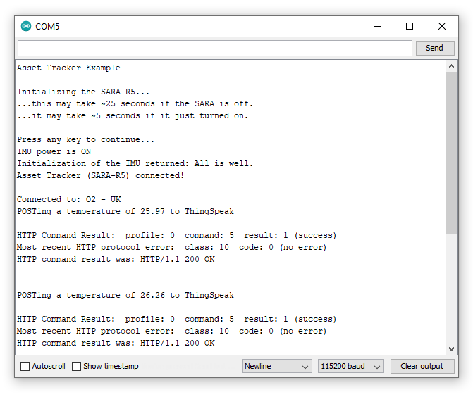
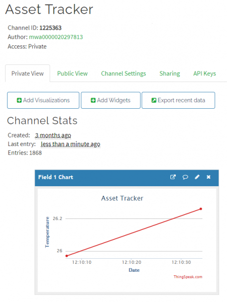
The example code reads the temperature from the Asset Tracker IMU and POSTs it to ThingSpeak. It will be added to your ThingSpeak channel as "Field 1".
If you open your serial monitor at 115200 baud the code prints out over serial the data sent to ThingSpeak:
Check your ThingSpeak channel and you should see data posted to it similar to the screenshot below:
Examples 20-22: Production Tests
Examples 20 - 22 are the ones we use using Asset Tracker production tests to check if the SARA’s I/O pins are connected correctly. We’ve included them as you might find them useful if you want to control the pins on the SARA. The examples use the SARA’s +UTEST mode to control the pins. Please consult the SARA-R5 AT Command Reference for further details.
Troubleshooting
In this section we'll go over a few troubleshooting tips for common snags and questions using the MicroMod Asset Tracker Carrier Board.
LTE Network Availability
The SARA-R5 supports LTE-M and NB-IoT data communication for multi-regional use. Please check the LTE signal availability for your area before purchasing a SARA-R5 product and selecting an LTE service provider / operator.
Data Connectivity
When working through the data connectivity examples, it is important that you run examples 13, 14 and 17 in order, before moving on to example 18 or 19. Each example builds on the last and together they configure the SARA’s data connection correctly.
TP (1PPS) Pin and LED
At the time of writing, we are shipping the SARA-R5 on the Asset Tracker with firmware version 02.06 on it. 02.06 contains a feature (which is just a polite name for a bug!) which means the 1 Pulse-Per-Second from the GNSS does work, but the pulse is only ~3 microseconds wide and cannot be adjusted. Handy huh? u-blox are aware of this - in fact we told them about it - and a fix is coming but they haven’t added it yet. We will keep an eye out for it and update this section once the fix is released.
Just to complicate matters, 3 microseconds is too short for the buffer FET and LED connected to the timing pulse to respond. So, we regret that you cannot currently use the TP PTH. We will share the fix with you as soon as we have it. The SARA firmware is easy to update using the Asset Tracker Firmware Update Tool.
NB/IoT Compatibility
The SparkFun MicroMod Asset Tracker uses the "00B" product version of the SARA-R5 module (specifically the SARA-R510M8S-00B-00). LTE NB-IoT Radio Access Technology, and the LTE FDD bands: 66, 71, 85 are not supported by this version.
General Troubleshooting Help
If you need technical assistance and more information on a product that is not working as you expected, we recommend heading on over to the SparkFun Technical Assistance page for some initial troubleshooting.
If you don't find what you need there, the SparkFun Forums: MicroMod are a great place to find and ask for help. If this is your first visit, you'll need to create a Forum Account to search product forums and post questions.
Resources and Going Further
Now that you've successfully got your MicroMod Asset Tracker Carrier Board up and running with your Processor Board, it's time to incorporate it into your own tracking project! For more information, check out the resources below:
MicroMod Asset Tracker Carrier Documentation:
u-blox SARA-R5 LTE-M / NB-IoT module Documentation:
- Datasheet (PDF)
- AT Command Set (PDF)
- System Integration Manual (PDF)
- Application Development Guide (PDF)
- Internet Applications Development Guide (PDF)
- GNSS Integration App Note (PDF)
- Firmware Update App Note (PDF)
MicroMod Documentation:
Users looking to update the firmware on their Asset Tracker Carrier Board using the MicroMod Update Tool should read through our MicroMod Update Tool Hookup Guide:
MicroMod Update Tool Hookup Guide
Need some inspiration for your next project? Check out some of these related tutorials with MicroMod:
