MAX30105 Particle and Pulse Ox Sensor Hookup Guide
MAX30105 Breakout Overview
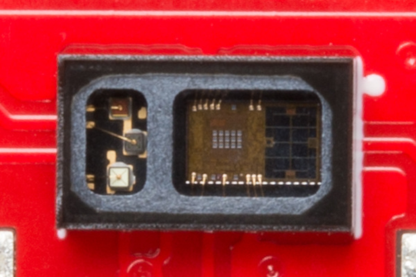
The MAX30105 has three on-board LEDs (seen on the left). Maxim recommends these LEDs be powered from 5V, but we've found the LEDs work fine at 3.3V. The red and IR LEDs are guaranteed to work at 3.3V, but the green LED may need 3.5V. It's best to try out your board at 3.3V and see if the green LED illuminates.
The IC itself runs at 1.8V, so we’ve included the interface logic to allow you to hook the MAX30105 Breakout Board to any board that has 5V, 3.3V, even 1.8V level I/O.
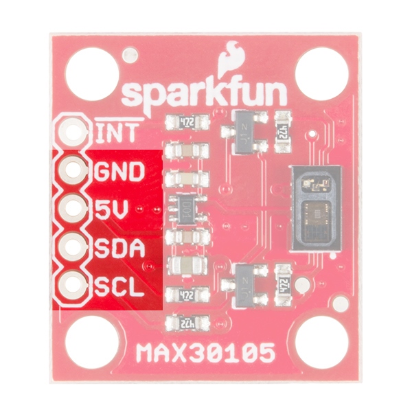
| Pin Label | Input/Output | Description |
|---|---|---|
| INT | Output | Interrupt, active low |
| GND | Supply Input | Ground (0V) supply |
| 5V | Supply Input | Power supply |
| SDA | Bi-directional | I2C bus clock line |
| SCL | Input | I2C bus clock line |
The GND/5V/SDA/SCL pin-out is the standard I2C connection on most of our products. This allows you to easily connect I2C boards to many of our platforms.
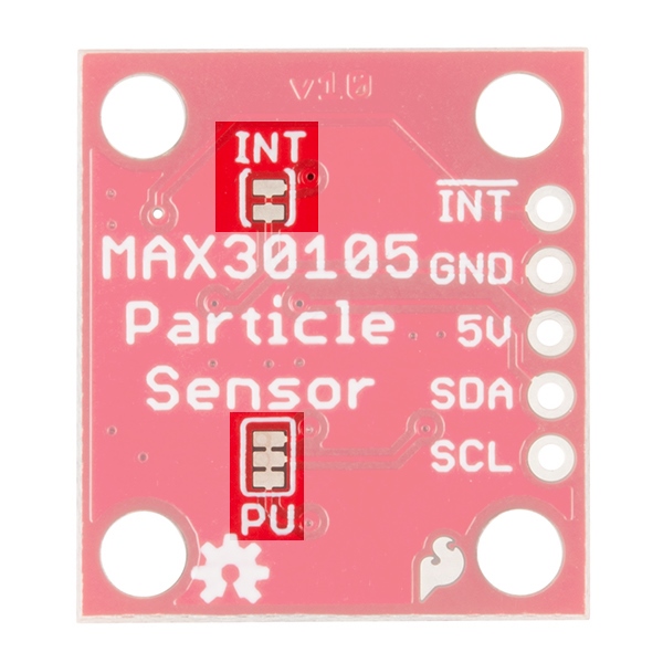
There are two jumpers on the back of the PCB:
The PU jumper is used on many I2C boards to allow the user to disconnect the 4.7k Ohm pull-up (PU) resistors from the SDA and SCL lines. By default, this jumper is closed meaning there are 4.7k pull-up resistors on SDA and SCL. If this is the only device on the I2C bus, then this jumper should be left closed. If there are multiple I2C devices or breakout boards on the bus with pull-up resistors, then the traces in this jumper should be cut to remove the 4.7k Ohm resistors from the bus. If needed, the jumper can be re-soldered to close it again in the future.
The INT jumper is used to control the pull-up resistor on the interrupt pin. The INT jumper is closed by default, which means a 4.7k resistor is pulling up the interrupt pin. The INT pin on the MAX30105 is an open drain pin. If there is only one board on your I2C bus, this jumper should be left closed. If there are multiple boards on the I2C bus sharing a single interrupt pin, this jumper can be cut to disconnect the pull up resistor.


