Make Your Own Fritzing Parts
 HelloTechie
Schematic View
Custom Schematic SVG
Go back to either Illustrator, Inkscape, or the vector graphic editor you are using. Open up the Fritzing's SchematicViewGraphic_Template.svg in the downloaded Fonts and Templates folder. You can also open the example SparkFun T5403 Barometer Breakout schematic SVG template file from the SparkFun Fritzing Parts Github repo.
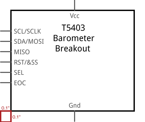
When editing the schematic to match your board, you will want to make sure each connector pin is shown. You will want to change the pin labels to match the connector pin names. Depending on your part, you might have to resize the template schematic. Make sure there is 0.1” space between the main part symbol square and the edge of the outer pins.
Save SVG
You will want make sure to save as a new SVG. Remember to have a naming convention that will be easy to tell the difference between the other SVG files you are creating for your Fritzing part.
Editing Schematic View in Parts Editor
Load SVG
Go back to the Parts Editor, and click on the Schematic button to go to the Schematic view. Go to File->Load image for view. Next, you will select the schematic SVG you just created, and click Open. The part should be now in the Fritzing (New) Parts Editor.
Set Connector Pins
If you look at the Connectors window on the right side, you will notice that your pin names are already there. When you make a change to the connector pin's name and description in either Breadboard, Schematic, PCB, or Connectors view, the Parts Editor will automatically change the connector pin's name and description for the other views. Also, the connector type (male, female, or pad) will still be the same.
Just like you did in Breadboard view, you will still need to select a graphic for each pin. Click on the 'Select graphic' button, and choose the appropriate graphic for that pin. For the Schematic view, you are going to want to change the Terminal point, so the connecting wires are connecting at the furthest point.
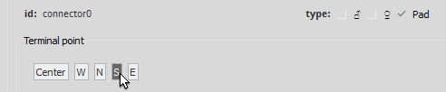
The easiest way to do this is make sure the connector pin’s graphic is still selected, and change the Terminal point in the Connectors window. For the GND graphic, the Terminal point is moved to the south end by clicking on “S”.
Repeat for All Connectors
After you update all your connector pins you can move on to Editing in PCB view.