Make Your Own Fritzing Parts
 HelloTechie
Breadboard View - Parts Editor
Load Image
After you created your custom breadboard image, you will want to load the breadboard SVG in the Fritzing (New) Parts Editor. First, go back to the Fritzing (New) Parts Editor and click the Breadboard button to get into the Breadboard view. Go to File->Load image for view.
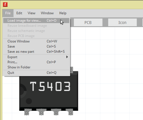
Next, you will select the breadboard SVG you just created and hit Open. The graphic should be now in the Fritzing (New) Parts Editor.
Connectors
When working in the main Fritzing application, you connect different Fritzing parts with colored wires to show how the parts connect to one and another. In order for Fritzing to know where connector pins are on a board or part, you will need to tell Fritzing where those connectors are.
Name and Description for Connector Pins
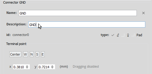
For the Breadboard view, the Connectors window will be on the right side of the Fritzing (New) Parts Editor. Select a pin to change the name of the pin and to add a description.
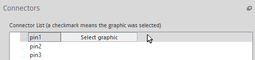
Select the Connector Pin's Graphic
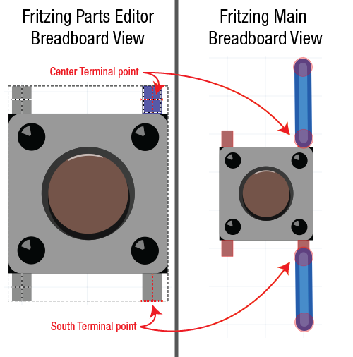
Click on the Select graphic button on the right of your connector pin's name. Then, click on the connector pin's graphic. This will set the Anchor point. The Anchor point is the location where the wire connects to that connector. By default the Terminal point will show up in the middle of the selected graphic. If you want to move the Terminal point, you are able to click on the Terminal point and hold to move. You can also change the Terminal point by clicking on either “Center”, “W”, “N”, “S”, or “E” in the Connectors window.
Change Connector Type
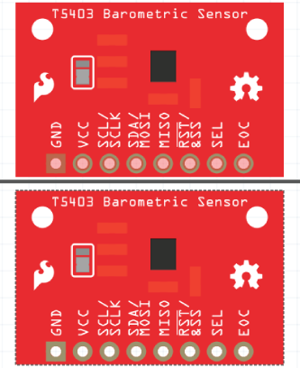
Change the type of connector in the Connectors window. You can choose from male, female, or pad. For the SparkFun T5403 Barometer Breakout, all the connector pins are female.
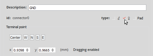
In the image below, you can see the differences between setting the connector type as male vs female.
Repeat for All Connector Pins
Name, select the appropriate graphic, and change the connector type for all your connector pins. You can also set Internal Connections in the Connectors window.