Make Your Own Fritzing Parts
 HelloTechie
PCB View
Making custom PCB SVG
Go back to either Illustrator, Inkscape, or the vector graphic editor you are using. When making a custom PCB SVG, the main image groups you will need are copper (which will have all your connector pads) and silkscreen.
Create the PCB Graphic
You can either start fresh when creating a PCB SVG, modify your custom breadboard SVG, or edit the Fritzing's PCBViewGraphic_Template.svg in the downloaded Fonts and Templates folder. For this example, the custom breadboard SVG was modified, and the file was saved as a new SVG called SFE_T5403_Barometer_Breakout_PCB.svg.
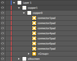
Make Sure to have Two Copper Groups
When setting up your layers, make sure to have two copper groups. All of your connector layers should be in the copper groups. When you do this, Fritzing will know that the component has the copper connectors on both sides of the PCB.
Make Sure the Connector Pins' Spacing is Accurate
It is important to have the PCB connector pins match accurately with your board and to have the appropriate spacing between pins. Fritzing offers a PCB Fab services. If you or other Fritzing users want to use that service with your custom part, you will want to make sure your PCB view is accurate.
Graphic Standards
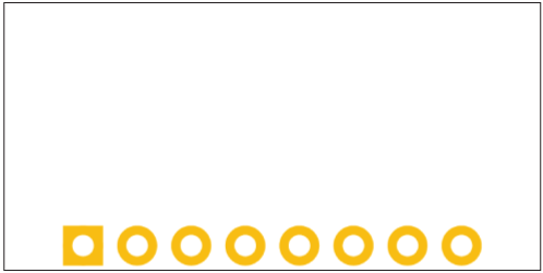
Instead of the connector pins being a copper/tinned green color, the PCB view connector pins are the "copper" color:

The main changes made from the custom breadboard SVG is that the main groups are copper and silkscreen. The silkscreen will still be white.
Editing PCB View in Parts Editor
Go back to the Parts Editor, and click on the PCB button to get to PCB view. Go to File->Load image for view. Next, you will select the PCB SVG you just created, and click Open. The part should be now in the Fritzing (New) Parts Editor.
Update Connector Pins
Select the appropriate graphics for each connector pin, just like you did in Breadboard and Schematic view.