LTE Cat M1/NB-IoT Shield Hookup Guide
Hardware Overview
It may not look like it, but there's a lot going on on the LTE Cat M1/NB-IoT Shield. This page covers all of the hardware features included on the board. Take a quick peruse through it to make sure you don't get tripped up by the UART- or power-select switches, the power/reset buttons, or the external USB and GPS interfaces.
Oops! We accidentally tied the AREF pin to GND. This shouldn't affect the overall functionality of the shield; however, it does affect the use of the analog pins on the microcontroller board (A0 - A5).
Update: We have fixed the AREF pin issue with version v11 of the shield.
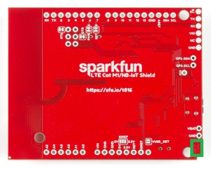
Version marking on the bottom of the shield.
Power Supply
The u-blox SARA-R410M-02B module uses a relatively low amount of power. Peak current consumption is about 200mA (a far cry from past cellular shields which occasionally pulled upwards of 2A) at a voltage supply of 3.3V. Logic on the module is all 1.8V, but never fear -- we've included logic-level shifting included on-board (see the Logic-Level Selection section for more information).
The shield is designed to take power from one of three sources:
- Arduino -- The shield receives power from the Arduino's 5V supply pin.
- LiPo Battery -- A 3.7-4.2V LiPo battery can be connected to the black 2-pin JST connector.
- On-board micro-B USB connector -- A micro-B USB cable can be connected from your computer or a USB wall wart to supply power to the shield. This may be useful if you're using the shield as more of a "breakout board." (This connector can also be used to provide a USB interface to the u-blox module -- see the USB Interface section below).
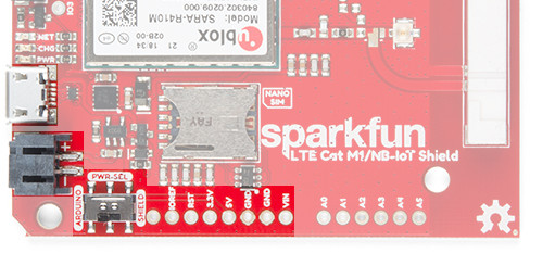
The PWR_SEL switch should be used to select the power source. In the Arduino position, the shield will receive power from the Arduino. In the SHIELD position, the shield will supply power to the Arduino.
LiPo Charging
The shield includes an MCP73831 LiPo charger, which is configured to power a single-cell LiPo battery at up to 500mA.
The battery can be charged by either connecting a micro-B USB cable to the shield, or by connecting the shield to a powered Arduino and setting the PWR_SEL switch to ARDUINO.
Power and Reset Buttons
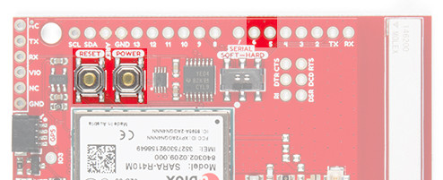
The LTE Cat M1/NB-IoT Shield includes a pair of SPST buttons labeled RESET and POWER. These are connected directly to the SARA-R4 module's PWR_ON and RESET_N pins.
By default the SARA-R4 module is turned off, to turn it on -- as you might any other cell phone -- you need to hold the POWER button down for about 3 seconds.
The RESET button resets the SARA-R4 module to its default configuration. In most cases you should not need to use this button. If you do, hold it down for at least 10 seconds while the module is on. Note that this button has no affect on the Arduino -- it won't reset your sketch.
Both of these pins are also wired to the Arduino:
| Pin Function | Button Label | Arduino Pin | Description |
|---|---|---|---|
| Power On | POWER | 5 | Power the SARA-R4 module on or off. Hold for ~3 seconds. |
| Reset | RESET | 6 | Reset the SARA-R4 module configuration to default. Hold for >10 seconds |
The library is designed to toggle the POWER pin if the shield is not communicating, so you may be able to avoid pressing this button at all.
UART Interface
All communication between your Arduino and the SARA-R4 module will occur via an AT command interface over a simple UART -- RX and TX pins.
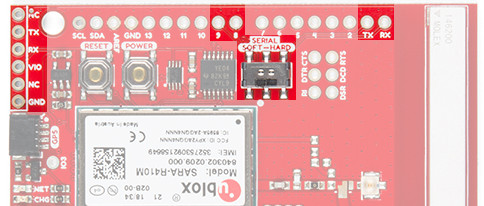
Designed with a simple Arduino Uno in mind, this shield can either communicate with the SARA-R4 module via either a hardware or software serial interface. The SERIAL switch can either be set to HARD for hardware serial on pins 0/1 or SOFT for software serial on pins 8/9.
| Arduino Receive (Cell Transmit) | Arduino Transmit (Cell Receive) | |
|---|---|---|
| Software Serial | 8 | 9 |
| Hardware Serial | 0 | 1 |
FTDI Header
The UART signals are also broken out to a 6-pin "FTDI" serial header. If you're not using the shield as a shield -- more-so as a breakout -- this header may be useful. You can connect any 3.3V or 5V USB-to-Serial converter (like the Serial Basic) to this header, and directly communicate with the SARA-R4's UART.
This header is not affected by the SERIAL-select switch. External power must be supplied to the LTE shield -- either via USB or LiPo battery.
LED Indicators
A trio of LEDs are broken out between the USB and GPS connectors. The table below documents each of these LEDs color and indication:
| LED Label | LED Color | LED indication |
|---|---|---|
| PWR | Red | Power supplied to SARA-R4 module |
| CHG | Yellow | LiPo battery charging (may illuminate if no battery is connected) |
| NET | Blue | Cellular network status. Illuminates when the SARA-R4 module is connected to a cellular network. (Must be configured in software.) |
The most important of these LEDs is the blue "NET" indicator. This LED will illuminate when your SARA-R4 module is properly configured, is connected to a SIM card, and is communicating with a cell network. By default, the pin SARA-R4 connected to this LED is not configured, but the library should take care of that upon initialization.
Logic-Level Selection
The SARA-R4 module's GPIO pins all operate at 1.8V logic levels. Fortunately, the shield includes level shifting which should convert either 3.3V or 5V signals to 1.8V.
On most Arduino, selection of the high end of the logic-level translation should be automatic. Voltage supplied from the Arduino's IOREF pin should set it. If so, ignore what comes next.
If your Arduino does not have an IOREF pin, or does not supply a valid logic level on that pin, you should use the IOREF jumper to select your Arduino's logic level.
GPS Port
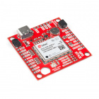
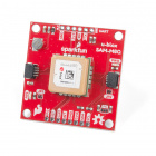
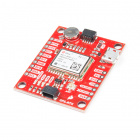
If you want to easily add location-tracking to your project, the LTE Shield's Qwiic GPS port can connect to a handful of u-blox GPS modules. We're adding more compatible modules soon. For now, the supported modules are:
The LTE Shield Arduino library includes support for reading this GPS module via the SARA-R4's AT command set.
Note that this Qwiic connector is only designed to support u-blox-based GPS modules. It does not support any other GPS modules or sensors.
LTE Antenna
The LTE Shield includes a ceramic, SMD antenna -- a Molex 1462000001. The antenna has a gain of 3.8dBi around 1.7GHz to 2.7GHz.
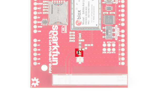
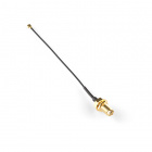
If your project requires an external antenna, the onboard antenna can be disconnected and the included U.FL antenna can be used. To disconnect the onboard ceramic antenna, grab a hobby knife and slice across the big metal pad near the U.FL connector -- between the two, white, silkscreen dots as highlighted in the image below along a black line.
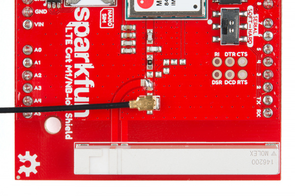
Once the jumper has been cut, add a solder jumper to connect the center pad to the pad located just above the u.FL connector, and carefully connect the u.FL part of your external antenna. Your setup should look like the image below.
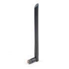
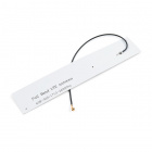
Once you've adjusted the jumpers, it's safe to add your own antenna via a U.FL connector. A couple options include the LTE Antenna 175mm Duck SMA Male - VT4GLTE-R-10 and LTE Antenna 100mm FPC u.FL - VT4GFIA-6.
LTE Antenna 100mm FPC U.FL - VT4GFIA-6
CEL-15053USB Interface
The SARA-R4 features a USB interface which, with the proper drivers installed, can provide your Raspberry Pi or, really, any other machine with a USB interface to Cat M1/NB-IoT. Using the LTE Shield's USB interface is almost as simple as plugging in a USB cable to your computers USB port.
Unfortunately, the UART and USB interfaces can not be used concurrently. To use the USB interface, close the VUSB_DET jumper on the back side of the board.
