LTE Cat M1/NB-IoT Shield Hookup Guide
Introduction
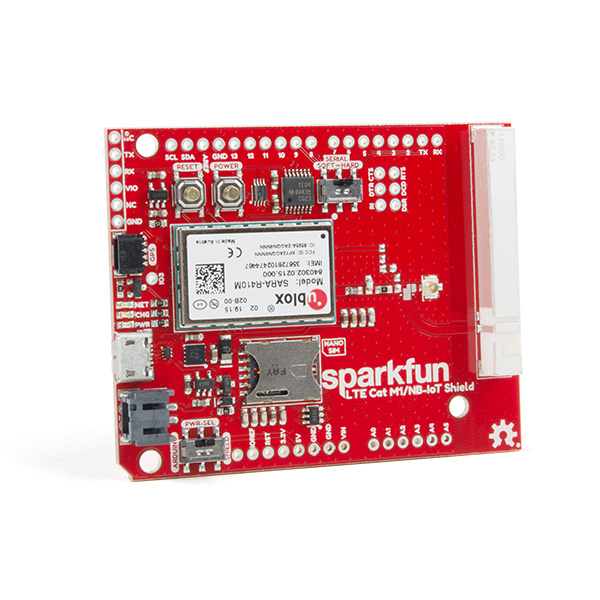
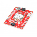
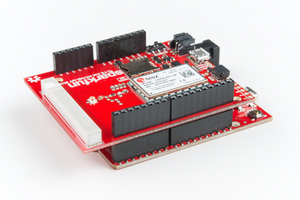
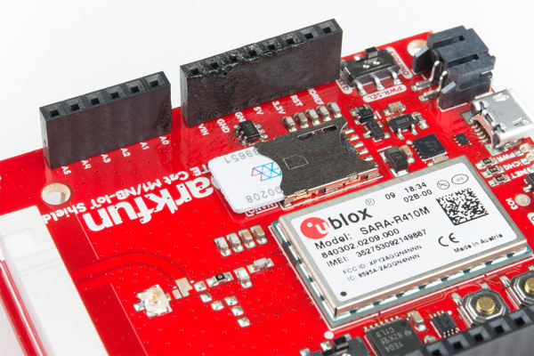
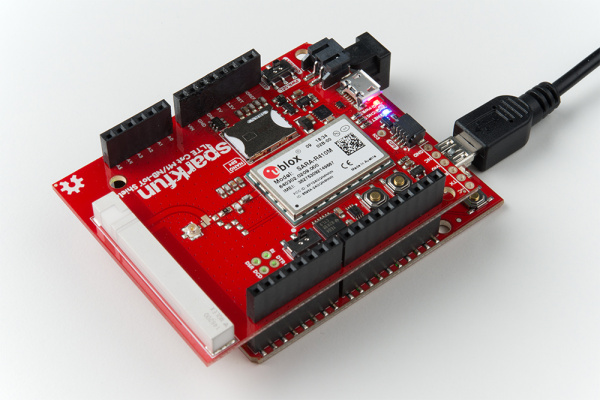
The SparkFun LTE Cat M1/NB-IoT Shield equips your Arduino or Arduino-compatible microcontroller with access to data networks across the globe. It adds wireless, high-bandwidth cellular functionality to your IoT project while maintaining low power consumption and a small footprint.
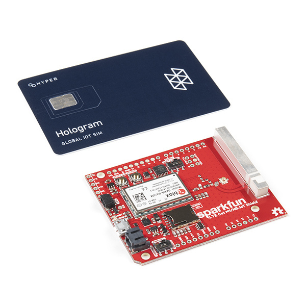
You can either purchase the SparkFun LTE Cat M1/NB-IoT Shield individually, as in the link above, or packaged with a Hologram SIM card. The Hologram SIM card provides global connectivity on an extremely reasonable pricing model. They also provide software tools like cloud data and SMS messaging and webhooks for routing data from your cell shield to popular web services.
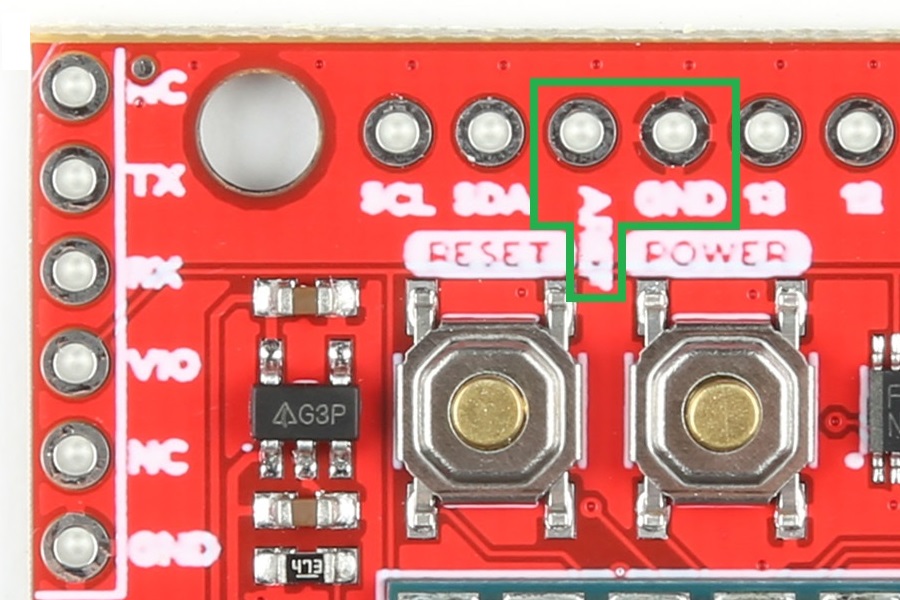
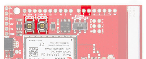
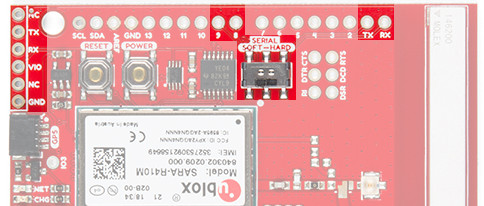
Revision Update: In the latest revision of the SparkFun LTE Cat M1/NB-IoT Shield, we have fixed the AREF pin that was accidentally tied to ground. If users are unsure about which version they purchased, please refer to the pictures of the updated changes, shown below.
At the heart of the LTE Cat M1/NB-IoT shield is a u-blox SARA-R410M-02B LTE Cat M1/NB-IoT modem. Cat M1 (Category M1) and NB-IoT (Narrowband IoT) are both Low Power Wide Area Network (LPWAN) technologies that are designed to provide cellular communication to small IoT devices. They operate on LTE network bands just like most smartphones, and should be supported by most cellular network carriers.
The u-blox module commmunicates over a UART via a simple AT command set. We've provided a library to help you get started with everything from sending SMS text messages to communicating with servers over a TCP/IP connection.
Both the module and library support an I2C GPS interface, so you can plug in a u-blox GPS module and start remotely tracking your project.
Required Materials
In addition to the shield itself, we recommend the following items to follow along with this tutorial. You may not need everything though depending on what you have. Add it to your cart, read through the guide, and adjust the cart as necessary.
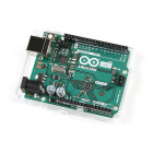
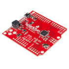
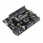
Arduino or Arduino-Compatible Development Board -- The LTE Cat M1/NB-IoT Shield is primarily designed to work as a...shield. It should be compatible with most Arduino-type development boards, including the Arduino Uno, SparkFun RedBoard, SparkFun BlackBoard, and SAMD21 Dev Breakout.
SparkFun BlackBoard
SPX-14669The shield can also be used as a breakout board for the u-blox SARA-R4 module, in which case nearly any microcontroller development board with a free UART should work. You can even use the shield's USB interface with a Raspberry Pi, Raspberry Pi Zero or, really, any Windows/Mac/Linux device with a free USB port.
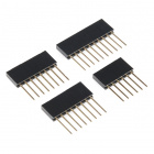
Headers -- To connect the shield to your Arduino you'll need to solder headers into it. We recommend the stackable R3 headers, but male headers can also do the trick.
Soldering Tools -- You'll also need soldering tools to connect the headers to your shield. A basic soldering iron and solder should be enough.
SIM card -- A nano SIM card will be required to provide connectivity for the LTE CAT-M1 Shield's u-blox module. If you've purchased the Hologram/SparkFun LTE Shield Combo, then you're all set. Otherwise, there are a variety of connectivity suppliers including AT&T, T-Mobile, and Verizon.
Optional Materials
In addition to those required items, these bits and pieces can help add functionality to your LTE Shield, so you can take it even further:
LiPo Battery -- The LTE Shield includes a LiPo battery charger. This LiPo can be used to power both your Arduino and the shield simultaneously. Any of the below batteries should work with the shield:
Lithium Ion Battery - 1Ah
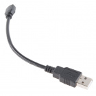
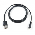
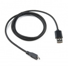
PRT-13813Micro-B USB cable -- The shield's SARA-R4 module supports a USB interface, which can be used for both power and a communication interface. A micro-B USB cable isn't required, but may be helpful if you want to power your project via USB or give the SARA-R4 module's USB interface a spin.
SparkFun Traveler microB Cable - 1m
CAB-14741SparkFun Rugged microB Cable - 1m
CAB-14742Suggested Viewing
Suggested Reading
This tutorial builds on a variety of electronics, programming, and engineering concepts. If any of the subjects of these tutorials sound foreign to you, consider checking them out before continuing on:
Serial Communication
Installing an Arduino Library
Logic Levels
Three Quick Tips About Using U.FL
If you aren't familiar with the Qwiic system, we also recommend reading here for an overview.
 |
| Qwiic Connect System |
Hardware Overview
It may not look like it, but there's a lot going on on the LTE Cat M1/NB-IoT Shield. This page covers all of the hardware features included on the board. Take a quick peruse through it to make sure you don't get tripped up by the UART- or power-select switches, the power/reset buttons, or the external USB and GPS interfaces.
Oops! We accidentally tied the AREF pin to GND. This shouldn't affect the overall functionality of the shield; however, it does affect the use of the analog pins on the microcontroller board (A0 - A5).
Update: We have fixed the AREF pin issue with version v11 of the shield.
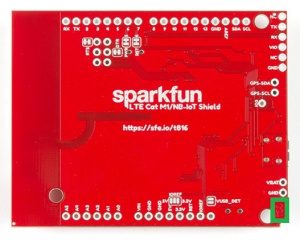
Version marking on the bottom of the shield.
Power Supply
The u-blox SARA-R410M-02B module uses a relatively low amount of power. Peak current consumption is about 200mA (a far cry from past cellular shields which occasionally pulled upwards of 2A) at a voltage supply of 3.3V. Logic on the module is all 1.8V, but never fear -- we've included logic-level shifting included on-board (see the Logic-Level Selection section for more information).
The shield is designed to take power from one of three sources:
- Arduino -- The shield receives power from the Arduino's 5V supply pin.
- LiPo Battery -- A 3.7-4.2V LiPo battery can be connected to the black 2-pin JST connector.
- On-board micro-B USB connector -- A micro-B USB cable can be connected from your computer or a USB wall wart to supply power to the shield. This may be useful if you're using the shield as more of a "breakout board." (This connector can also be used to provide a USB interface to the u-blox module -- see the USB Interface section below).
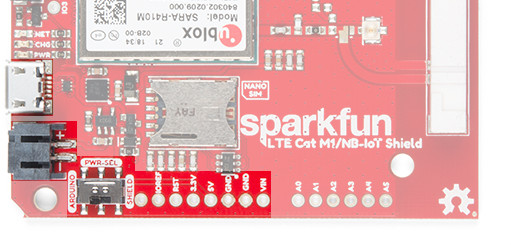
The PWR_SEL switch should be used to select the power source. In the Arduino position, the shield will receive power from the Arduino. In the SHIELD position, the shield will supply power to the Arduino.
LiPo Charging
The shield includes an MCP73831 LiPo charger, which is configured to power a single-cell LiPo battery at up to 500mA.
The battery can be charged by either connecting a micro-B USB cable to the shield, or by connecting the shield to a powered Arduino and setting the PWR_SEL switch to ARDUINO.
Power and Reset Buttons
The LTE Cat M1/NB-IoT Shield includes a pair of SPST buttons labeled RESET and POWER. These are connected directly to the SARA-R4 module's PWR_ON and RESET_N pins.
By default the SARA-R4 module is turned off, to turn it on -- as you might any other cell phone -- you need to hold the POWER button down for about 3 seconds.
The RESET button resets the SARA-R4 module to its default configuration. In most cases you should not need to use this button. If you do, hold it down for at least 10 seconds while the module is on. Note that this button has no affect on the Arduino -- it won't reset your sketch.
Both of these pins are also wired to the Arduino:
| Pin Function | Button Label | Arduino Pin | Description |
|---|---|---|---|
| Power On | POWER | 5 | Power the SARA-R4 module on or off. Hold for ~3 seconds. |
| Reset | RESET | 6 | Reset the SARA-R4 module configuration to default. Hold for >10 seconds |
The library is designed to toggle the POWER pin if the shield is not communicating, so you may be able to avoid pressing this button at all.
UART Interface
All communication between your Arduino and the SARA-R4 module will occur via an AT command interface over a simple UART -- RX and TX pins.
Designed with a simple Arduino Uno in mind, this shield can either communicate with the SARA-R4 module via either a hardware or software serial interface. The SERIAL switch can either be set to HARD for hardware serial on pins 0/1 or SOFT for software serial on pins 8/9.
| Arduino Receive (Cell Transmit) | Arduino Transmit (Cell Receive) | |
|---|---|---|
| Software Serial | 8 | 9 |
| Hardware Serial | 0 | 1 |
FTDI Header
The UART signals are also broken out to a 6-pin "FTDI" serial header. If you're not using the shield as a shield -- more-so as a breakout -- this header may be useful. You can connect any 3.3V or 5V USB-to-Serial converter (like the Serial Basic) to this header, and directly communicate with the SARA-R4's UART.
This header is not affected by the SERIAL-select switch. External power must be supplied to the LTE shield -- either via USB or LiPo battery.
LED Indicators
A trio of LEDs are broken out between the USB and GPS connectors. The table below documents each of these LEDs color and indication:
| LED Label | LED Color | LED indication |
|---|---|---|
| PWR | Red | Power supplied to SARA-R4 module |
| CHG | Yellow | LiPo battery charging (may illuminate if no battery is connected) |
| NET | Blue | Cellular network status. Illuminates when the SARA-R4 module is connected to a cellular network. (Must be configured in software.) |
The most important of these LEDs is the blue "NET" indicator. This LED will illuminate when your SARA-R4 module is properly configured, is connected to a SIM card, and is communicating with a cell network. By default, the pin SARA-R4 connected to this LED is not configured, but the library should take care of that upon initialization.
Logic-Level Selection
The SARA-R4 module's GPIO pins all operate at 1.8V logic levels. Fortunately, the shield includes level shifting which should convert either 3.3V or 5V signals to 1.8V.
On most Arduino, selection of the high end of the logic-level translation should be automatic. Voltage supplied from the Arduino's IOREF pin should set it. If so, ignore what comes next.
If your Arduino does not have an IOREF pin, or does not supply a valid logic level on that pin, you should use the IOREF jumper to select your Arduino's logic level.
GPS Port
If you want to easily add location-tracking to your project, the LTE Shield's Qwiic GPS port can connect to a handful of u-blox GPS modules. We're adding more compatible modules soon. For now, the supported modules are:
The LTE Shield Arduino library includes support for reading this GPS module via the SARA-R4's AT command set.
Note that this Qwiic connector is only designed to support u-blox-based GPS modules. It does not support any other GPS modules or sensors.
LTE Antenna
The LTE Shield includes a ceramic, SMD antenna -- a Molex 1462000001. The antenna has a gain of 3.8dBi around 1.7GHz to 2.7GHz.
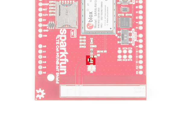
If your project requires an external antenna, the onboard antenna can be disconnected and the included U.FL antenna can be used. To disconnect the onboard ceramic antenna, grab a hobby knife and slice across the big metal pad near the U.FL connector -- between the two, white, silkscreen dots as highlighted in the image below along a black line.
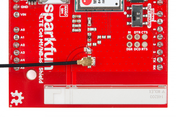
Once the jumper has been cut, add a solder jumper to connect the center pad to the pad located just above the u.FL connector, and carefully connect the u.FL part of your external antenna. Your setup should look like the image below.
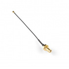
Once you've adjusted the jumpers, it's safe to add your own antenna via a U.FL connector. A couple options include the LTE Antenna 175mm Duck SMA Male - VT4GLTE-R-10 and LTE Antenna 100mm FPC u.FL - VT4GFIA-6.
LTE Antenna 100mm FPC U.FL - VT4GFIA-6
CEL-15053USB Interface
The SARA-R4 features a USB interface which, with the proper drivers installed, can provide your Raspberry Pi or, really, any other machine with a USB interface to Cat M1/NB-IoT. Using the LTE Shield's USB interface is almost as simple as plugging in a USB cable to your computers USB port.
Unfortunately, the UART and USB interfaces can not be used concurrently. To use the USB interface, close the VUSB_DET jumper on the back side of the board.
Hardware Hookup
To assemble the LTE Shield, you'll need basic soldering tools and skills. New to soldering? No worries! Check out our through-hole soldering tutorial.
How to Solder: Through-Hole Soldering
Solder on Headers
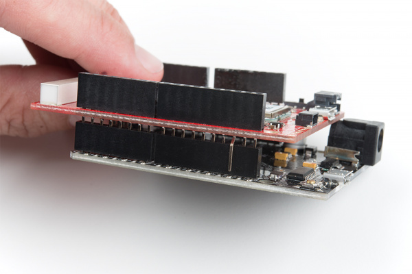
To connect the SparkFun LTE Shield to your Arduino, you'll need to solder headers into the through-hole Arduino pins. We recommend either Stackable headers -- if you want to stack more shields on top -- or male headers.
Soldering into the two 8-pin, one 6-pin, and one 10-pin header should be enough to get your shield snugly fitting and electrically connected.
Plug in a SIM Card
You'll also need to slide an activated SIM card into your shield. As you insert the SIM card, its "notch" should match the pattern on the board's silkscreen as well as that on the SIM card holder itself.
Don't forget to activate your SIM if that's required by your network provider!
Activate Your Hologram SIM
If you're using a SIM card from Hologram, you'll need to follow a few quick steps to activate your SIM card.
- Log in to your Hologram account, or create one
- Click the blue + Activate SIM button in the upper-right-corner of your Dashboard.
- Select your plan – in most cases “Maker Flexible” is the way to go, but you can upgrade.
- Enter your SIM card’s CCID. This number can be found printed on both your nano-SIM card and in the larger digits below the bar code. Then select continue.
- Next you can decide whether to enable auto-refill or not and continue. Finally, you’ll be greeted with a summary page – hit “Activate” and you’re ready to go!
For more help activating your Hologram SIM card, check out their Connect Your Device documentation.
Supply Power
Once you've soldered on the headers, and plugged in at least a SIM card. It's time to supply power and start LTE'ing!
The shield can be powered via either an Arduino or the on-board USB or LiPo battery connectors. For the purposes of this tutorial, we'd recommend powering via Arduino.
Set the PWR_SEL switch to ARDUINO. Plug the shield into your Arduino, then plug your Arduino into your computer via USB.
Once plugged in, you should see the shield's red PWR LED illuminate (you may also see the yellow CHG LED turn on as well -- even without a battery plugged in -- no worries.) The blue NET LED will probably not turn on yet. For that, we need to configure the shield. And for that, we need the SparkFun LTE Shield Arduino Library. Read on!
LTE Shield Arduino Library
The SparkFun LTE Shield Arduino library is designed to simply interface your Arduino to the Cat M1/NB-IoT Shield. The shield handles everything from initialization (turning on the SARA-R4 module, configuring your network, setting GPIO modes) to sending/receiving SMS and communicating over a TCP network interface.
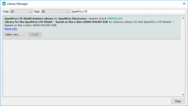
The SparkFun LTE Shield Library is available in the Arduino library manager. In the Arduino IDE, navigate to Sketch > Include Library > Manage Libraries. Then in the search box, begin searching for "SparkFun LTE Shield." Once your search is narrowed down, select the SparkFun LTE Shield library and click "Install."
Otherwise, you can manually download the library, navigate to GitHub repository and download the repository as a ZIP folder (or click the link below):
To manually install the library via a ZIP folder, open Arduino, navigate to Sketch > Include Library > Add .ZIP Library, and select the ZIP folder you just downloaded.
Example 0: Network Registration
The first example in this tutorial is the most critical. Here we demonstrate how to configure your LTE Shield's SARA-R4 module to communicate with your network of choice. This is a configuration that usually only needs to happen once. After you've successfully run this sketch, your Arduino should be all set up for SMS and TCP/IP messaging.
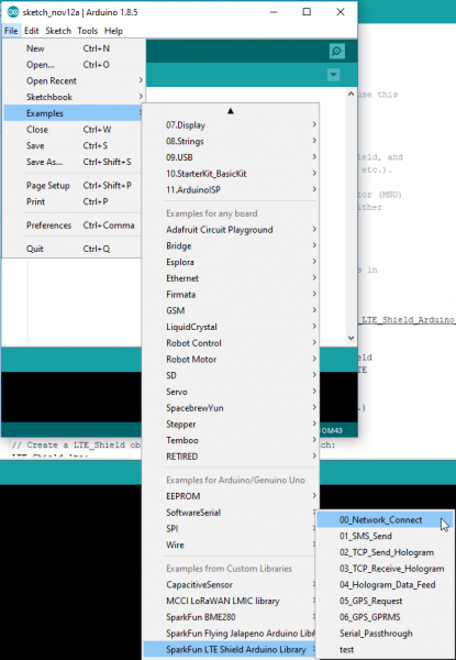
To begin, load up this example by going to File > Examples > SparkFun_LTE_Shield_Arduino_Library > 00_Register_Operator.
Before uploading the sketch, you may need to adjust the value of MOBILE_NETWORK_OPERATOR and APN. The first variable, sent as a parameter to lte.setNetwork, defines the mobile network operator your LTE shield should configure itself to communicate with. It should be one of the below values:
language:c
// Network operator can be set to either:
// MNO_SW_DEFAULT -- DEFAULT
// MNO_ATT -- AT&T
// MNO_VERIZON -- Verizon
// MNO_TELSTRA -- Telstra
// MNO_TMO -- T-Mobile
const mobile_network_operator_t MOBILE_NETWORK_OPERATOR = MNO_SW_DEFAULT;
const String MOBILE_NETWORK_STRINGS[] = {"Default", "SIM_ICCD", "AT&T", "VERIZON",
  "TELSTRA", "T-Mobile", "CT"};
Your access point name (APN), is provided by your SIM card provider. If you're using a Hologram SIM, this should be a string'ed "hologram". This value is provided to the lte.setAPN() function.
language:c
// APN -- Access Point Name. Gateway between GPRS MNO
// and another computer network. E.g. \"hologram\"
const String APN = "hologram";
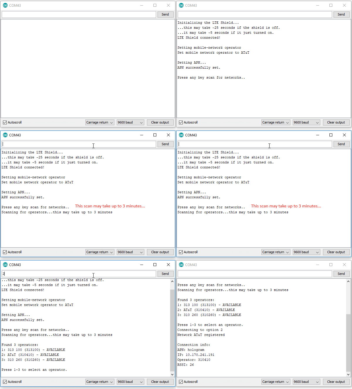
After uploading the sketch, open up your serial monitor to check the status of your shield's registration. This example is interactive. After possible network operators are scanned, you'll need to enter one of a handful of options to attempt connecting to that operator.
You'll need to be a little patient after uploading this sketch. Depending on the state of your shield, it can take about 30 seconds for the sketch to initialize your shield. It can also take up to three minutes for the shield to scan for network operators in its area.
Some times your choice of network operator will be limited to a set of numerical-only options -- a combination of mobile country codes (MMC) and mobile network codes (MNC). For example, AT&T in the example above is an MCC/MNC combination of 310 and 410, respectively -- that's the operator we select. ("313 100" is an AT&T First Responders Network and "310 260" is T-Mobile.)
Notes on Mobile Country Codes (MCC) and Mobile Network Codes (MNC)
Sometimes your choice of network operator will be limited to a set of numerical-only options. This will be a combination of mobile country codes (MCC) and mobile network codes (MNC). For example, AT&T in the example above is an MCC/MNC combination of 310 and 410, respectively – that’s the operator we select. (“313 100” is an AT&T First Responders Network and “310 260” is T-Mobile.)
If you need to do some digging to discover which MMC/MNC is which, check out the searchable, comprehensive list at mcc-mnc.com and/or The Roaming Zone.
Note: if you leave a region covered by a pair of country/network codes, you may need to reconfigure your shield using this sketch.
What's Going On at Start-Up
The LTE Shield can take a handful of seconds to start up if you've just plugged it in and haven't triggered the power button.
As it initializes communication with the shield, the Arduino library must attempt to verify that the shield is on while also tuning the baud rate down from a potentially unknown baud rate (though, most likely, 115200 bps) to 9600 bps.
On start-up, the library will cycle through the SARA-R4's supported baud rates, and attempt to establish communication. This process may take up to 5 seconds. If the shield doesn't respond, the library will assume it's powered off. It will cycle the POWER button, then start the "autobaud" process over again.
In all, this process can take up to 30 seconds. You should end up with a SARA-R4 module configured at 9600 baud, and ready to begin LTE'ing.
Note: You can shorten this initial power-on time by manually turning on the SARA-R4's power (hold the POWER button down for ~3 seconds).
Initializing the LTE Shield Library
There are a few declarations and function calls you'll need in every LTE Shield library sketch.
Global Definitions
There's, of course, the library include statement:
language:c
#include <SparkFun_LTE_Shield_Arduino_Library.h>
If you're using a software serial port -- as the examples demonstrate -- you'll also need to define a SoftwareSerial object with RX on pin 8 and TX on pin 9:
language:c
// We need to pass a Serial or SoftwareSerial object to the LTE Shield
// library. Below creates a SoftwareSerial object on the standard LTE
// Shield RX/TX pins:
SoftwareSerial lteSerial(8, 9);
And, finally, you'll need to declare an LTE_Shield object, which we'll use throughout the sketch for SMS-sending, and TCP/IP interactions. This object optionally takes two parameters -- the POWER and RESET Arduino pins. By default these parameters should match the shield defaults, so they are not usually required.
language:c
// Create a LTE_Shield object to be used throughout the sketch:
#define POWER_PIN 5
#define RESET_PIN 6
LTE_Shield lte(POWER_PIN, RESET_PIN);
Setup Requirements
With your global variables declared, initializing the shield library is as simple as calling lte.begin(SerialPort). SerialPort should either be the SoftwareSerial port you declared in globals, or a hardware serial port if that's supported by your Arduino board.
begin() will return true on a successful initialization of the shield or false if communication with the SARA-R4 module fails.
The examples in this library all assume a software serial port on pins 8 and 9. So the begin statement below should work.
language:c
if ( lte.begin(lteSerial) ) {
  Serial.println("Successfully initialized the LTE shield via software serial!");
}
If, on the other hand, you're using a hardware serial port (on pins 0/1) to communicate with the shield, the begin statement below may be used:
language:c
if ( lte.begin(Serial1) ) {
    Serial.println("Initialied SARA-R4 module on a hardware serial port.");
}
The library will take care of all the begin(), write(), and read() functions provided by your serial port.
Example 1: Send an SMS
Our next example in the LTE Shield Arduino library demonstrates how to send an SMS. Note that this example does require your SIM card's plan supports outbound SMS text messages -- they may incur a fee, so be mindful of how often you run the sketch.
To load this sketch, navigate to File > Examples > SparkFun LTE Shield Arduino Library > 01_SMS_Send.
Before uploading the code, modify the value of DESTINATION_NUMBER to that of your desired text message destination.
language:c
// Set the cell phone number to be texted
String DESTINATION_NUMBER = "11234567890";
Note that the SMS destination number should include the country code (e.g. "1" for US). For example, to text SparkFun (if SparkFun's corporate phones could receive SMS messages) at 303-284-0979, you'd set the DESTINATION_NUMBER string to "13032840979".
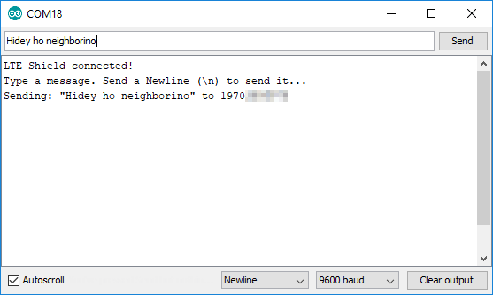
Once your destination phone number is set, upload the code and open your serial monitor (9600 baud). In the serial monitor, set the line-ending dropdown to "Newline.".
Then type a message and send it. After a few seconds you should see a text message appear on your destination phone.
Using the Arduino Library's SMS-Send Functionality
The sendSMS function should be pretty straightforward to use. The function takes two parameters: a String'ed phone number and a String'ed message to send.
language:c
LTE_Shield_error_t LTE_Shield::sendSMS(String number, String message);
Consider building a String variable before sending it to the sendSMS function. You can add variables -- including digitalRead()'s and analogRead()'s to the String by using the String() operator. The powerful String object includes easy concatenation with the += operator (or concat()). For example:
language:c
String messageToSend;
int time = millis();
messageToSend = "A0 = " + String(analogRead(A0)); // Add A0 to
messageToSend += "\r\n"; // Create a new line
messageToSend += "Time = " + String(time);
lte.sendSMS(DESTINATION_NUMBER, messageToSend);
The sendSMS function does return an error/success response. Check for a return value of LTE_SHIELD_SUCCESS (set to 0) on success, or a value greater than 0 on an error.
Example 2: Send a Hologram Message
Our next example demonstrates how to send a message to the Internet via the SARA-R4's support for TCP/IP protocols.
Load this example by opening File > Examples > SparkFun LTE Shield Arduino Library > 02_TCP_Send_Hologram.
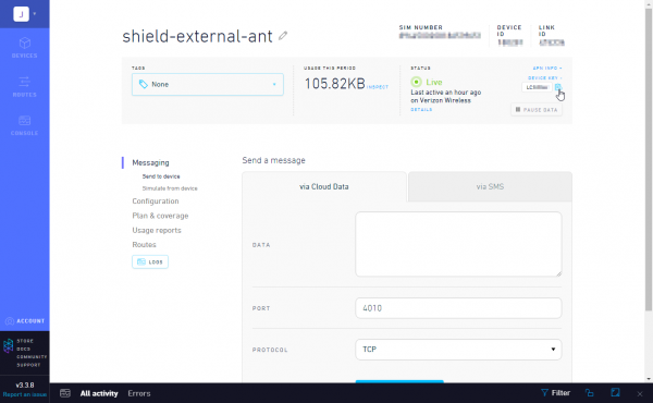
Before uploading this example, you'll need your Hologram device's device key. This can be found in your Hologram dashboard. Navigate to your device, and click the "DEVICE KEY +" in the top-left-ish corner.
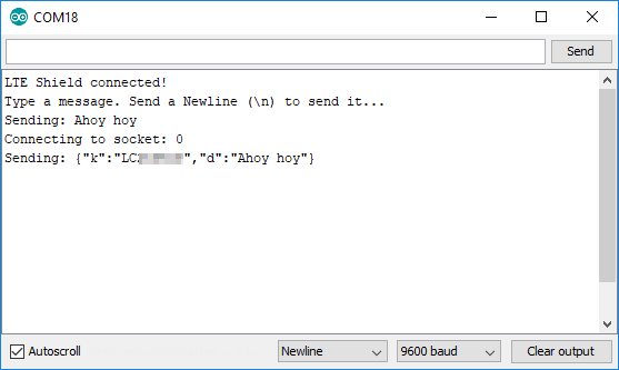
With that set, upload away! Then open the serial monitor at 9600 baud. As with the previous example, set your line-ending setting to Newline.
Open up your Hologram dashboard, then, from the serial monitor, type a message you'd like to send to the Hologram messaging server.
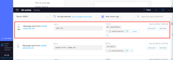
After a few seconds, you should see the message appear in your device's Hologram dashboard.
Using TCP/IP Sockets
This example demonstrates how to use the LTE Shield's TCP/IP socket capabilities. Sockets are a very common interprocess communication tool for sending and/or receiving data across a variety of networking protocols. In this case, we'll be using socket to send data over a TCP network link. The SARA-R4 module supports up to seven concurrently-open sockets -- usually we'll only need one-or-two at a time.
To begin, open a socket with the socketOpen function. This function takes one parameter -- an indication of whether you want to open a TCP or UDP socket. Possible parameters are LTE_SHIELD_TCP or LTE_SHIELD_UDP.
language:c
int socket;
socket = lte.socketOpen(LTE_SHIELD_TCP);
if (socket < 0) {
  Serial.println("Unable to open a socket");
}
socketOpen should return a value between 0 and 6. This is your socket -- protect it well!
Once your socket is open, it's time to use it to connect to a server. For that, there's the socketConnect function. This function takes a socket number, URL or IP address, and port to connect to. In this example we use the socket received from socketOpen and use it to connect to hologram.io on port 9999.
language:c
const char HOLOGRAM_URL [] = "cloudsocket.hologram.io";
const unsigned int HOLOGRAM_PORT = 9999;
if (lte.socketConnect(socket, HOLOGRAM_URL, HOLOGRAM_PORT) == LTE_SHIELD_SUCCESS) {
  // Send our message to the server:
  Serial.println("Connected to Hologram server!"));
}
Once you're connected to the server, it's time to send some data! For that, there's the socketWrite function. This function takes, again, a socket, and a String'ed message. You'll need to be careful with the message if you're sending it to the Hologram servers. It should be a JSON-encoded String of the format described here: https://hologram.io/docs/reference/cloud/embedded/#send-a-message-to-the-hologram-cloud. (See the example code for help constructing a compatible JSON string.)
language:c
String message = "{\"k\": \"a8F8asd4\", \"d\":\"Hello, world!\"}"
if (lte.socketWrite(socket, message) == LTE_SHIELD_SUCCESS) {
  Serial.println("Successfully sent message!");
}
Finally, you can close a socket using the socketClose function. Sometimes a server will close the socket on its side, but it helps to sometimes be pre-emptive in your socket-closing.
language:c
if (lte.socketClose(socket) == LTE_SHIELD_SUCCES) {
  Serial.println("Sucessfully closed a socket!");
}
Example 3: Receive a Hologram Message
Now that you've sent a message via TCP/IP services, this example demonstrates how to create a local listening socket on your LTE Shield to receive data.
Again, this example uses Hologram to send a message from a web portal down to the shield. If you don't have a Hologram SIM, consider checking out the library-how-to at the end.
To load up the TCP receive example go to File > Examples > SparkFun LTE Shield Arduino Library > 03_TCP_Receive_Hologram.
You shouldn't need to modify anything in this example. Just upload away! After uploading open up your serial monitor. Then open up your Hologram dashboard.
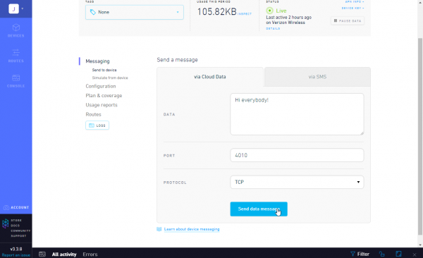
Next, from your device's Hologram dashboard type a message to send **via Cloud Data* and send that data message (keep the Port as 4010 and protocol as TCP).
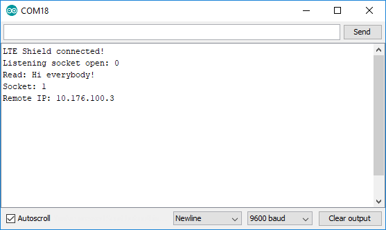
After not too-long, you should see the message pop up in your Serial Monitor.
Listening, Callbacks, and Polling
This example builds on using sockets from the last example, and introduces a couple new concepts as well.
socketListen can be used after opening a socket to set up a listening port on the SARA-R4 module. This function takes a socket to use and a port to listen on -- 4010 in this example.
language:c
if (lte.socketListen(socket, 4010) == LTE_SHIELD_SUCCESS) {
  Serial.println("Listening on socket 4010");
}
While a socket is open and listening, data comes into the SARA-R4 module asynchronously. To catch this data, the library implements a poll function, which should be called as often as possible in the loop(). poll() is designed to monitor the UART, and, if it sees data come in from a socket, relay that back to the Arduino sketch.
To pull in data from the poll() function, a callback is used. This callback should provide two parameters: an int socket and a String message. The example below demonstrates how to declare a socket-read callback, register it, and poll for data:
language:c

void processSocketRead(int socket, String message) {
  Serial.println("Read: " + message);
  Serial.println("From: " + String(lte.lastRemoteIP()));
  Serial.println("Socket: " + String(socket));
}

void setup() {
  // Provide setSocketReadCallback a pointer to our socket-read callback
  lte.setSocketReadCallback(&processSocketRead);
}

void loop() {
  // Poll as much as possible to catch asynchronous data coming into LTE Shield
  lte.poll();
}
This example also demonstrates a similar callback functionality to take action on an asynchronously-closed socket. setSocketCloseCallback() can be used to set a closed-socket callback. The callback should take a single parameter -- the socket closed. The example uses this callback to re-open a listening socket if that's what the closed socket was.
Troubleshooting
If you are running into trouble with your LTE shield, here are some troubleshooting tips and guides that may help you figure out what might be going on:
Troubleshooting Resources
Troubleshooting Steps
- To begin troubleshooting your shield, make sure you are following the hookup guide exactly.
Why? The assembly instructions and example codes have been tested and are known to work. It will also be easier to narrow down the problem because any deviation from the hookup guide may be causing the issue(s). - Use the SparkFun Troubleshooting Tips to do an initial check of any issues you may have missed. These include, but are not limited to:
- Double checking your power. Use a multimeter to it is getting the right voltage or enough current?
- Double check your soldering. Are there any cold joints?
- Double checking your wiring or connections and use a multimeter to test all connections.
- Do you have the right board selected in the Arduino IDE? Are you using the right COM port?
- Double check the baud rate for the Serial Monitor.
- Have you tried a different computer, USB cable, or microcontroller board?
- etc.
- Verify that your Hologram SIM card is activated. If you have reached the free 1MB data limit, you will need to wait for the next month/billing cycle or add a payment method for your account.
- Check your area of coverage. Hologram has a wide variety of contract carriers, but they do not have coverage everywhere. If you or your project are in an area with low or minimal cellular coverage, you may run into issues because of that.
- As part of our QC process, all shields should have been tested with a known working Hologram SIM card. However, here are a few tests and sketches you can run to verify the functionality of the board. (*These tests assume that you have already addressed the previous items 1-4 and you are testing the shield in the US. If you live outside of the US, you may need to modify the library for your carrier information.)
- Without the LTE shield, upload Blink to make sure your microcontroller is working.
With the LTE shield on the RedBoard:
- Check the hardware connections for continuity, switch positions, make sure the SIM card is inserted fully, and check that there is power going to the LTE module. (i.e. Uploading code, while the switch is in the SERIAL - [HARD] position will cause issues.)
- Don't forget to use the push buttons to power/reset the LTE module.
- Run the Serial_Passthrough example code to verify the microcontroller can talk to the LTE shield.
- Run the
Ping_SIM_card.ino( Click Link) to verify that you are reading the SIM card. You may need to run this sketch a few times, there were a small number of instances that is gave false negatives. However, a failure here could indicate that your SIM card isn't seated properly or there is a connection issue. - Run the 00_Register_Operator example sketch from the library. This will be the first sketch that tests the functionality of the LTE shield.
- You may need to adjust the mobile network operator (MNO) setting on line 45.
- You may also need to set the APN on line 51 .
- Run the Network_Info example sketch from the library. This sketch initializes the LTE module and checks that it can connect to a mobile network.
- You may need to adjust the mobile network operator (MNO) setting on line 83.
Frequently Asked Questions
Are the Hologram eUICC SIM Card's Special Features Supported with the LTE Cat M1/NB-IoT Shield?
The Hologram enhanced eUICC SIM card [ e.g. CEL-17117 ] will work with SparkFun LTE CAT M1/NB-IoT Shield - SARA-R4 [ e.g. CEL-14997 ] but the special eUICC features will not be operable with the shield at this current time.
If you need further assistance with these key features please visit the Hologram support forum:
Resource & Going Further
We hope this tutorial was informative and helps get you started with building an awesome, remote, connected project!
If you need any more information on the LTE Cat M1/NB-IoT Shield or the Arduino library, here are some resources to consider:
- SparkFun LTE Cat M1//NB-IoT Shield GitHub Repository
- Hardware
- Schematic:
- Schematic (PDF) -- v10 PDF of the LTE Shield schematic
- Schematic (PDF) -- v11 PDF of the LTE Shield schematic
- Eagle Files:
- Eagle Files (ZIP) -- v10 Eagle PCB design files
- Eagle Files (ZIP) -- v11 Eagle PCB design files
- u-blox SARA-R4 Datasheet (PDF)
- Ceramic Antenna Datasheet (PDF)
- Schematic:
- Software
- SFE Product Showcase
If you are using the Hologram SIM card, check out the resources below
- Hologram - Global IoT platform provider for SIM cards
- Documentation hub -- Wealth of guides, FAQ's, and tutorials documenting all of Hologram's products and services.
For more tutorials, more to learn, and more project-inspiration, check out these related tutorials:
