LSM6DS3 Breakout Hookup Guide
Introduction
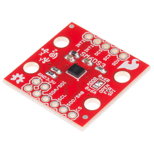
The LSM6DS3 is a accelerometer and gyroscope sensor with a giant 8 kbyte buffer and embedded processing interrupt functions, specifically targed at the cellphone market. The sensor is super-flexible and can be configured specifically for an application. We've put together a driver and slew of examples to help you explore the possibilities.
Some of the things the LSM6DS3 can do:
- Read accelerometer data up to 6.7 kilosamples per second, for super accurate movement sensing
- Read gyroscope data up to 1.7 kilosamples per second
- Operates at 1.25mA for up to 1.7 ksps modes
- Read temperature
- Buffer up to 8 kbytes of data between reads (built-in FIFO)
- Count steps (Pedometer)
- Detect shocks, tilt, motion, taps, double-taps
- Host other sensors into its FIFO
- Drive interrupt pins by embedded functions or by FIFO low-capacity/overflow warning.
Covered In This Tutorial
This tutorial gives you all you need to get going with the LSM6DS3. We'll introduce you to the chip itself, then the breakout board. Then we'll switch over to example code and show you how to interface with the board using an Arduino and our SparkFun LSM6DS3 Arduino library.
The tutorial is split into the following pages:
- LSM6DS3 Overview -- Basic information
- Hardware Overview -- Hardware connections
- Assembly -- Connect to the LSM6DS3 by I2C or SPI
- Installing the Arduino Library -- Includes overview of the examples
- Using the Arduino Library -- explains the user API
- Theory and Example Data -- Advanced driver diagrams and graphs of recorded data
- Resources and Going Further -- Links to the datasheet and application notes, plus inspirational projects
Required Materials
Get the datasheet and application notes now. Open them in a non-browser viewer that can display the index/table of contents in a pane. There is so much information, paned viewing is a must!
This tutorial explains how to use the LSM6DS3 Breakout Board with an Arduino. To follow along, you'll need the following materials:
- LSM6DS3 Breakout Board
- Arduino UNO, RedBoard, or another Arduino-compatible board
- Straight Male Headers -- Or wire. Something to connect between the breakout and a breadboard.
- Breadboard -- Any size (even mini) should do.
- M/M Jumper Wires -- To connect between Arduino and breadboard.
A logic level shifter is required for any 5V-operating Arduino (UNO, RedBoard, Leonardo, etc). If you use a 3.3V-based 'duino -- like the Arduino Pro 3.3V or 3.3V Pro Mini -- there is no need for level shifting.
Suggested Reading
If you're not familiar with some of the concepts below, we recommend checking out that tutorial before continuing on.
Hardware Overview
The Pinout
In total, the LSM9DS0 Breakout breaks out 11 pins.
The bare-minimum connections required are broken out on the left side of the board. These are the power and I2C pins (the communication interface the board defaults to). These pins can be used for the SPI interface as well:
| Pin Label | Pin Function | Notes |
|---|---|---|
| GND | Ground | 0V voltage supply. Spare GND pin to connect more stuff! |
| VDD | Power Supply | Supply voltage to the chip. Should be regulated between 1.8V and 3.6V. Spare VDD provided for general use as well. |
| SDA/SDI | I2C: Serial Data SPI: MOSI | I2C: Serial data (bi-directional) SPI: Device data in (MOSI) |
| SCL | Serial Clock | I2C and SPI serial clock. |
| SDO/SA0 | I2C: Address SPI: MISO | I2C: Address LSB SPI: Device data out (MISO) |
| CS | I2C: Mode SPI: CS | I2C: Select I2C (disconnected) SPI: Chip select (Slave select) |
The remaining pins are broken out on the other side. These pins break out SPI functionality and interrupt outputs:
| Pin Label | Pin Function | Notes |
|---|---|---|
| INT2 | Accel/Gyro Interrupt 2 | INT1 and INT2 are programmable interrupts for the accelerometer and gyroscope. They can be set to alert on over/under thresholds, data ready, or FIFO overruns. Make sure these are connected to an INPUT pin to prevent driving 5v back into the LSM6DS3. |
| INT1 | Accel/Gyro Interrupt 1 | |
| OCS | Aux SPI 3-wire | These pins are used to attach slave I2C and 3-wire devices for FIFO data collection. This function is not covered in this tutorial. |
| SCX | Aux Clock | |
| SDX | Aux Data |
Power Supply
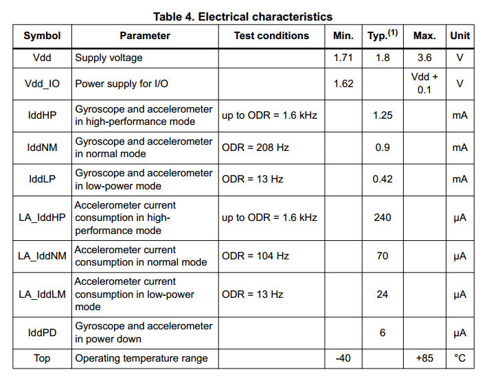
The VDD and GND pins are where you'll supply a voltage and 0V reference to the IC. The breakout board does not regulate this voltage, so make sure it falls within the allowed supply voltage range of the LSM9DS0: 1.8V to 3.6V. Below is the electrical characteristics table from the datasheet.
The communication pins are not 5V tolerant, so they'll need to be regulated to within a few mV of VDD.
Interrupts
There are a variety of interrupts on the LSM6DS3. While connecting these is not as critical as the communication or power supply pins, using them will help you get the most out of the chip.
The interrupt pins are INT1 and INT2. One or both pins can be software configured and mapped to the following conditions:
- Step detected
- Step detected after delta time
- Step counter overflowed
- Significant motion (shock, drop)
- FIFO full
- FIFO overrun
- FIFO threshold reached (Datasheet calls this the "watermark"
- Boot status
- Gyroscope data ready
- Accelerometer data ready
- Inactivity
- Single tap
- Wake-up
- Free-fall
- Double tap
- 6D (orientation)
- Tilt
- Timer
- Wake-up
- Ironing interrupt
Only a few interrupt examples are provided. See the datasheet and application guide for using the advanced interrupt features.
The Jumpers
| Jumper Label | Jumper Function |
|---|---|
| ADDR | Use to sellect address 0x6A or 0x6B(default) for I2C communication. This jumper must be opened for SPI mode, or the MISO line will not supply data |
| PU_EN | This trace-connected jumper enables 4.7k resistors on SDA and SCL for I2C. SPI works with these connected, but really they should be cut apart for better signal shape at high speeds and to lower power consumption |
| SCX and SDX | ST recommends pulling the unused SCX and SDX to power or ground when not in use. If connecting slave devices, cut these traces. |
The ADDR jumper is commonly reconfigured for I2C addresses and SPI mode, so it is solder jumpered.
The other jumpers are probably not for most users, but if it is necessary, whip out your handy hobby knife, and carefully cut the small traces between pads. Even if you're using SPI, though, the jumpers shouldn't hinder your ability to communicate with the chip.
Assembly
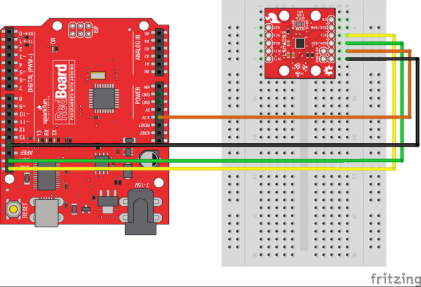
The easist way to connect the LSM6DS3 to an arduino compatible board is to use the I2C interface. The breadboard is shown for reference, but the wires can be soldered directly to the LSM6DS3 breakout and plugged into the arduino.
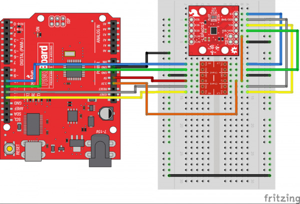
Here's how to connect the SPI lines to a 5V system using a SparkFun Logic Level Converter. Be sure to orient the converter's low side to the LSM6DS3. If using a teensy or other 3.3V microcontroller, the SPI lines can be connected directly.
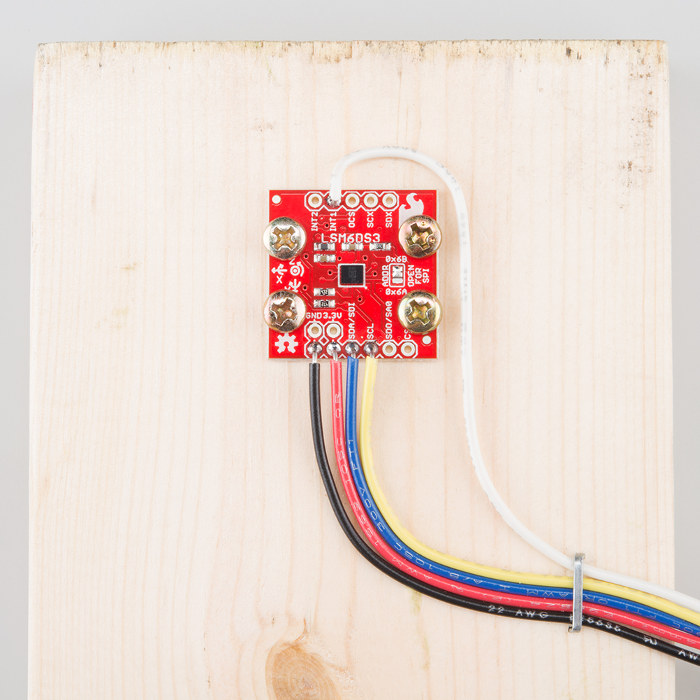
Use the 4 mounting holes to get the LSM6DS3 firmly attached to the thing that is being measured! Here, a 1x4 is used as a test platform to filter movement noise. Also shown here is a connection to the INT1 pin (Pin D3 on UNO and RedBoard). The other ends of the wires plug directly into the RedBoard.
Installing the Arduino Library
We've written an Arduino library to help make interfacing with the LSM6DS3's gyro, accelerometer, and temperature sensor as easy-as-possible. Visit the GitHub repository to download the most recent version of the library, or click the link below:
For help installing the library, check out our How To Install An Arduino Library tutorial. You'll need to move the SparkFun_LSM6DS3_Arduino_Library folder into a libraries folder within your Arduino sketchbook.
Alternatively, if you are running a relatively current version of the Arduino IDE (1.6.2 or newer) you will find the library in the library manager if you search for "LSM6DS3". For more details see the official Arduino library manager documentation.
Using the Arduino Library
Test the library
- MinimalistExample - The easiest configuration
Hook up the LSM6DS3 to the I2C bus, and click "File -> Examples -> Sparkfun LSM6DS3 Breakout -> MinimalistExample". This example demonstrates the highest level of usage. The default settings in the driver are I2C at the default address, 0x6B, so all you have to do is create a variable of the type "LSM6DS3" and .begin(); it.
Key parts:
language:c
LSM6DS3 myIMU; //Default constructor is I2C, addr 0x6B
This line creates a variable myIMU of type LSM6DS3. As the comment says, the default parameters are what we desire.
language:c
//Call .begin() to configure the IMU
myIMU.begin();
Calling .begin(); causes the driver to initialize the IMU. .begin can pass some diagnostics information back, but it's not necessary for this basic example.
language:c
  Serial.println(myIMU.readFloatAccelX(), 4);
Calling .readFloatAccelX() causes the driver to go get data from the IMU. In this line, the data is also passed to the print function.
Configure More Settings
- FifoExample - Demonstrates using the built-in buffer to burst-collect data - Good demonstration of settings
To get the most out of the LSM6DS3 you'll probably want to configure it. This sketch was put together as a template that shows you ALL the settings that the driver supports, and you can remove lines you don't need.
The creation of myIMU has a dark secret. If you're not using I2C, address 0x6B (defualt), you can specify your port during the construction. From the example,
language:c
LSM6DS3 myIMU( SPI_MODE, 10 );
...we specify SPI_MODE, a custom keyword, and pin 10. This makes use of the SPI interface and uses pin 10 for the CS line. As the logic is not arduino specific, any pin can be CS.
Here's the low-down on the arguments that can be used.
language:c
LSM6DS3 <your variable name>( SPI_MODE, <CS PIN NUMBER> );
...or...
language:c
LSM6DS3 <your variable name>( I2C_MODE, <address> );
...where address can be 0x6A or 0x6B.
Note: This example pulls a lot of data from the IMU. SPI is used for better performance.
The other settings:
language:c
//Over-ride default settings if desired
myIMU.settings.gyroEnabled = 1;  //Can be 0 or 1
myIMU.settings.gyroRange = 2000;   //Max deg/s.  Can be: 125, 245, 500, 1000, 2000
myIMU.settings.gyroSampleRate = 833;   //Hz.  Can be: 13, 26, 52, 104, 208, 416, 833, 1666
myIMU.settings.gyroBandWidth = 200;  //Hz.  Can be: 50, 100, 200, 400;
myIMU.settings.gyroFifoEnabled = 1;  //Set to include gyro in FIFO
myIMU.settings.gyroFifoDecimation = 1;  //set 1 for on /1

myIMU.settings.accelEnabled = 1;
myIMU.settings.accelRange = 16;      //Max G force readable.  Can be: 2, 4, 8, 16
myIMU.settings.accelSampleRate = 833;  //Hz.  Can be: 13, 26, 52, 104, 208, 416, 833, 1666, 3332, 6664, 13330
myIMU.settings.accelBandWidth = 200;  //Hz.  Can be: 50, 100, 200, 400;
myIMU.settings.accelFifoEnabled = 1;  //Set to include accelerometer in the FIFO
myIMU.settings.accelFifoDecimation = 1;  //set 1 for on /1
myIMU.settings.tempEnabled = 1;

//Non-basic mode settings
myIMU.settings.commMode = 1;

//FIFO control settings
myIMU.settings.fifoThreshold = 100;  //Can be 0 to 4096 (16 bit bytes)
myIMU.settings.fifoSampleRate = 50;  //Hz.  Can be: 10, 25, 50, 100, 200, 400, 800, 1600, 3300, 6600
myIMU.settings.fifoModeWord = 6;  //FIFO mode.
//FIFO mode.  Can be:
//  0 (Bypass mode, FIFO off)
//  1 (Stop when full)
//  3 (Continuous during trigger)
//  4 (Bypass until trigger)
//  6 (Continous mode)
Read the datasheet, and select the parameters that suit your needs. They can only take on the values listed, or the default value will be used. If you don't care about a setting, omit that line.
A Low-Level Example
- LowLevelExample - Demonstrates using only the core driver without math and settings overhead
This little example was put together to show you how to use the sensor without all the crazy floating point math. It saves memory in the processor (roughly half), but you won't have access to all the fancy math functions.
language:c
myIMU.writeRegister(LSM6DS3_ACC_GYRO_CTRL1_XL, dataToWrite)
and
language:c
myIMU.readRegister(&dataToWrite, LSM6DS3_ACC_GYRO_CTRL4_C);
show reading and writing to arbitrary registers
The Other Examples
- InterruptFreeFall - Embedded function demonstrating free-fall detection
- InterruptHWTapConfig - Embedded function demonstrating tap and double-tap detection
- MemoryPagingExample - Demonstrates switching between memory pages
- MultiI2C - Using two LSM6DS3s over I2C
- MultiSPI - Using two LSM6DS3s over SPI
- Pedometer - Embedded function demonstrating step-counting feature
User API Functions
Here's an explanation of the regular functions the user might call
Construction:
language:c
LSM6DS3( uint8_t busType, uint8_t inputArg );
busType can be SPI_MODE or I2C_MODE.
For SPI_MODE, inputArg specifies pin number for I2C_MODE, inputArg specifies either address 0x6A or 0x6B
language:c
status_t begin(void);
always call .begin(); before using the following functions!
language:c
int16_t readRawAccelX( void );
int16_t readRawAccelY( void );
int16_t readRawAccelZ( void );
int16_t readRawGyroX( void );
int16_t readRawGyroY( void );
int16_t readRawGyroZ( void );
These functions return the 16bit raw values from the LSM6DS3.
language:c
float readFloatAccelX( void );
float readFloatAccelY( void );
float readFloatAccelZ( void );
float readFloatGyroX( void );
float readFloatGyroY( void );
float readFloatGyroZ( void );
These functions return the floating point real-world values. Accel functions return in g's and Gyro return in degrees/second.
language:c
int16_t readRawTemp( void );
Gets the raw temperature value
language:c
float readTempC( void );
float readTempF( void );
Gets the temperature in your favorite scale (sorry, no kelvin)
These next functions operate the FIFO. Using the FIFO is more advanced and definitely requires consulting the datasheet for the LSM6DS3
language:c
void fifoBegin( void );
Configures the FIFO. This will make the FIFO start listening to Accelerometer data and/or gyroscope data, depending on the settings (the settings.accelFifoEnabled = 1; will include the accel in the fifo).
language:c
void fifoClear( void );
This clears the FIFO by reading out all the data and dumping it. If the FIFO is full and the bus is slow, this may take some time.
language:c
int16_t fifoRead( void );
Get the 16 bits of the next data coming out. This might be accelerometer data or gyroscope data, you can use the status bits to determine which (or by clearing out the FIFO completely and starting from a known reference).
language:c
uint16_t fifoGetStatus( void );
Get the 16 bits of the status word.
language:c
void fifoEnd( void );
Disables the FIFO.
Functions 'under the hood'
language:c
float calcGyro( int16_t );
float calcAccel( int16_t );
This converts raw values into real numbers. Internally, it uses the .settings to do the math. When using the high-level functions that return floating point numbers, these are internally called.
The only reason they are available to the user is because they can be used to convert the raw data coming out of the FIFO into real numbers. Though, if faster processing is needed (taking short-cuts or staying in raw integer math) they don't have to be used.
Theory and Example Data
From the nature of the examples, the LSM6DS3 can be used very simply (detect 'down', for example) to something much more complicated, like discerning arbitrary motion through space. We hope that after playing around with the examples, you'll take the library apart and do something truely amazing with it. This section gives you more information about what's going inside.
The Data
Sure, it's easy to read single points of data but if you really want good motion detection, you'll have to pull time-synchronized data and do math at it. The first step is to see what that data would look like, and practice algoritihms to see if your math is any good before you try to debug things in arduino.
Lets take a look at some actual data. Ideally we would use a robot to perfectly articulation the IMU through some test motion, but instead we used an engineer's arm. For the following tests, the IMU was held stationary, then moved down about 1 foot in about a half-second, then held stationary again. What follows is a select set of graphs.
These graphs show the same motion with several different settings. Notice that the raw data that is collected at these low-frequency sampling rates consists of steps. The higher the datarate, the finer the steps. Also notice that during what was felt as a smooth downward motion, sometimes non-monotonic slopes are seen, that is, the change in amplitude between steps doesn't always have the same sign.
Also shown in the graphs is a second trace -- but don't get too excited. This trace is a software filter created by implementing a rolling average of the last 20 samples. This was done with a teensy 3.1, and wasn't attempted with 328 based microcontroller.
Once the data is collected and filtered, then more advanced threshold and slope detectors can be implemented to get custom motion responses. This is similar to what the 'embedded functions' of the LSM6DS3 are actually doing to provide easy-to-use interrupt output.
Resources and Going Further
There are a gazillion ways to use an IMU, from simple gravity sensing to advanced motion tracking. There are so many ways to configure the LSM6DS3! After you've used your arduino and the examples to get the hang of things, use this process:
- Read the datasheet and application note!
- Design an experiment to try an idea
- Measure the results
Only this, is the way to improve.
Resources
- LSM6DS3 Product GitHub Repository -- Your revision-controlled source for all things LSM6DS3. Here you'll find our most up-to-date hardware layouts and code.
- LSM6DS3 Datasheet -- This datasheet covers everything from the hardware and pinout of the IC, to the register mapping of the gyroscope and accelerometer.
- LSM6DS3 Application Note -- This application note has the same information as the datasheet, but puts real english words in there to try and help out the humans. Use both this and the datasheet togheter in a tabbed PDF viewer, with the index window open, for maximum efficiency.
Going Further
Need a little inspiration? Check out some of these tutorials!
