Pi Servo Hat Hookup Guide
 SFUptownMaker
 Introduction
The SparkFun Pi Servo Hat allows your Raspberry Pi to control up to 16 servo motors via I2C connection. This saves GPIO and lets you use the onboard GPIO for other purposes. Furthermore, the Pi Servo Shield adds a serial terminal connection which will allow you to bring up a Raspberry Pi without having to hook it up to a monitor and keyboard.
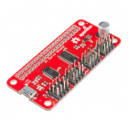
SparkFun Pi Servo HAT
DEV-14328Required Materials
Here's what you need to follow along with this tutorial. We suggest purchasing a blank microSD card rather than a NOOBS ready card, since the NOOBS ready cards may not have a new enough OS to support the Pi Zero W.

SparkFun Pi Servo HAT
DEV-14328In addition, you'll want some kind of servo motor to test the setup. Try testing the examples provided later in the tutorial with the generic sub-micro servo first.

Required Tools
No special tools are required to follow this product assembly. You will need a soldering iron, solder, and general soldering accessories.


Suggested Reading
You may want to review these tutorials before undertaking this one.
How to Solder: Through-Hole Soldering
Raspberry Pi SPI and I2C Tutorial
Hobby Servo Tutorial
Getting Started with the Raspberry Pi Zero Wireless
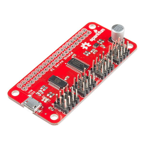
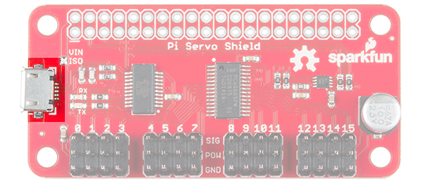
Hardware Overview
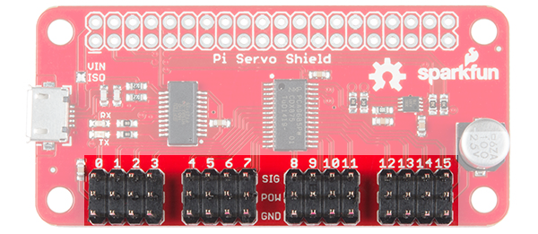
There are only a few items of interest on the board, as it is a hat designed to be minimally difficult to use.
USB Micro B Connector - This connector can be used to power the servo motors only, or to power the servo motors as well as the Pi that is connected to the hat. It can also be used to connect to the Pi via serial port connection to avoid having to use a monitor and keyboard for setting up the Pi.
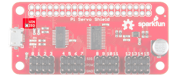
Power supply isolation jumper - This jumper can be cleared (it is closed by default) to isolate the servo power rail from the Pi 5V power rail. Why would you want to do that? If there are several servos, or large servos with a heavy load on them, the noise created on the power supply rail by the servo motors can cause undesired operation in the Pi, up to a complete reset or shutdown. Note that, so long as the Pi is powered, the serial interface will still work regardless of the state of this jumper.
Servo motor pin headers - These headers are spaced out to make it easier to attach servo motors to them. They are pinned out in the proper order for most hobby-type servo motor connectors.
Hardware Assembly
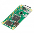
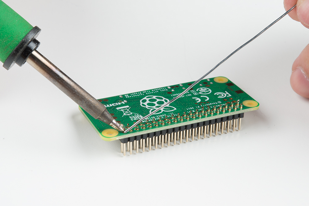
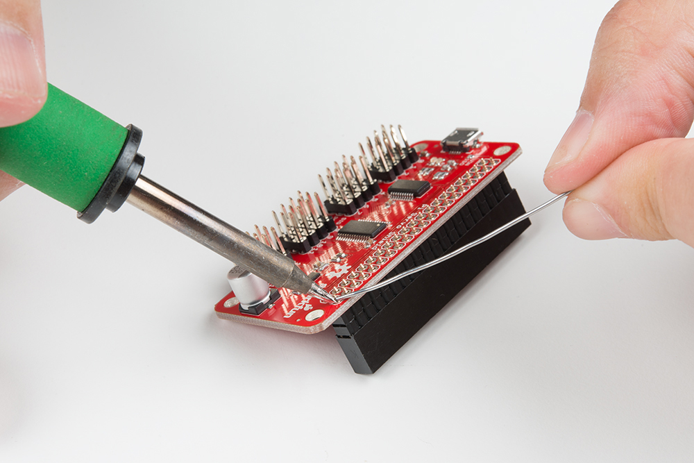
We suggest soldering the male headers onto the Pi Zero W.
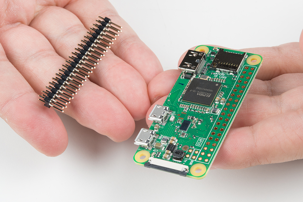
My favorite trick for this type of situtaion is to solder down one pin, then melt the solder on that pin with the iron held in my right hand and use my left hand to adjust the header until it sits flat as shown below. Make sure that you are soldering with the header's shorter side and the longer pins are on the component side. After tacking down one pin, finish soldering all the pins down to the Pi Zero W.
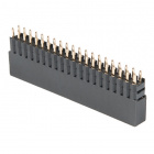
Repeat the steps with the female header and the Pi Servo Hat.
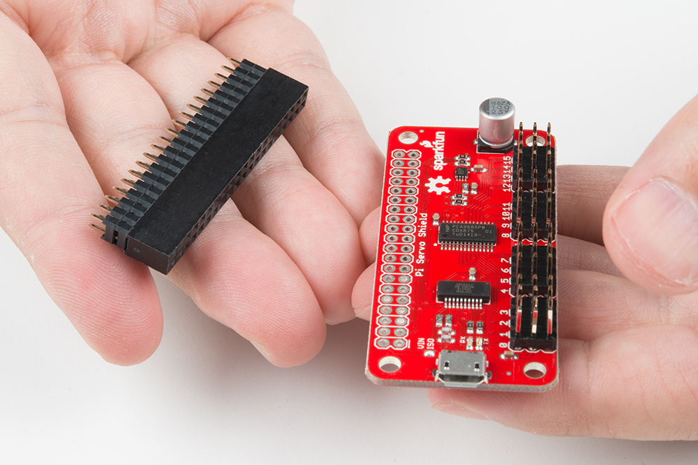
Make sure to insert the short pins from the bottom of the board and add solder to the component side so that the Pi Servo Hat stacks on top of the Pi Zero W's male header pins. You will also need to make sure that the header is sitting level before soldering down all the pins.
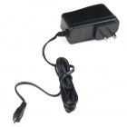
Once the headers have been soldered, stack the Pi Servo Hat on the Pi Zero W. Then connect a hobby servo to a channel "0" based on the servo that you are using. Try looking at the hobby servo's datasheet or referring to some of the standard servo connector pinouts listed in this tutorial. Using a sufficient 5V wall adapter, we can power the Pi Zero W. Plug the wall adapter into a wall outlet for power and connect the micro-B connector labeled as the "PWR IN" port on the Pi Zero W.
Software - Python
We'll go over in some detail here how to access and use the pi servo hat in Python. Full example code is available in the product GitHub repository.
Set Up Access to SMBus Resources
First point: in most OS level interactions, the I2C bus is referred to as SMBus. Thus we get our first lines of code. This imports the smbus module, creates an object of type SMBus, and attaches it to bus "1" of the Pi's various SMBuses.
language:python
import smbus
bus = smbus.SMBus(1)
We have to tell the program the part's address. By default, it is 0x40, so set a variable to that for later use.
language:python
addr = 0x40
Next, we want to enable the PWM chip and tell it to automatically increment addresses after a write (that lets us do single-operation multi-byte writes).
language:python
bus.write_byte_data(addr, 0, 0x20)
bus.write_byte_data(addr, 0xfe, 0x1e)
Write Values to the PWM Registers
That's all the setup that needs to be done. From here on out, we can write data to the PWM chip and expect to have it respond. Here's an example.
language:python
bus.write_word_data(addr, 0x06, 0)
bus.write_word_data(addr, 0x08, 1250)
The first write is to the "start time" register for channel 0. By default, the PWM frequency of the chip is 200Hz, or one pulse every 5ms. The start time register determines when the pulse goes high in the 5ms cycle. All channels are synchronized to that cycle. Generally, this should be written to 0.
The second write is to the "stop time" register, and it controls when the pulse should go low. The range for this value is from 0 to 4095, and each count represents one slice of that 5ms period (5ms/4095), or about 1.2us. Thus, the value of 1250 written above represents about 1.5ms of high time per 5ms period.
Servo motors get their control signal from that pulse width. Generally speaking, a pulse width of 1.5ms yields a "neutral" position, halfway between the extremes of the motor's range. 1.0ms yields approximately 90 degrees off center, and 2.0ms yields -90 degrees off center. In practice, those values may be slightly more or less than 90 degrees, and the motor may be capable of slightly more or less than 90 degrees of motion in either direction.
To address other channels, simply increase the address of the two registers above by 4. Thus, start time for channel 1 is 0x0A, for channel 2 is 0x0E, channel 3 is 0x12, etc. and stop time address for channel 1 is 0x0C, for channel 2 is 0x10, channel 3 is 0x14, etc. See the table below.
| Channel # | Start Address | Stop Address |
|---|---|---|
| Ch 0 | 0x06 | 0x08 |
| Ch 1 | 0x0A | 0x0C |
| Ch 2 | 0x0E | 0x10 |
| Ch 3 | 0x12 | 0x14 |
| Ch 4 | 0x16 | 0x18 |
| Ch 5 | 0x1A | 0x1C |
| Ch 6 | 0x1E | 0x20 |
| Ch 7 | 0x22 | 0x24 |
| Ch 8 | 0x26 | 0x28 |
| Ch 9 | 0x2A | 0x2C |
| Ch 10 | 0x2E | 0x30 |
| Ch 11 | 0x32 | 0x34 |
| Ch 12 | 0x36 | 0x38 |
| Ch 13 | 0x3A | 0x3C |
| Ch 14 | 0x3E | 0x40 |
| Ch 15 | 0x42 | 0x44 |
If you write a 0 to the start address, every degree of offset from 90 degrees requires 4.6 counts written to the stop address. In other words, multiply the number of degrees offset from neutral you wish to achieve by 4.6, then either add or subtract that result from 1250, depending on the direction of motion you wish. For example, a 45 degree offset from center would be 207 (45x4.6) counts either more or less than 1250, depending upon the direction you desire the motion to be in.
Software - C++
We'll go over in some detail here how to access and use the pi servo hat in C++. Note that it's much harder than it is in Python, so maybe now's the time to learn Python? Full example code is available in the product GitHub repository.
Include the Necessary Files
We'll start by going over the files which must be included.
language:cpp
#include <unistd.h> // required for I2C device access
#include <fcntl.h>  // required for I2C device configuration
#include <sys/ioctl.h> // required for I2C device usage
#include <linux/i2c-dev.h> // required for constant definitions
#include <stdio.h>  // required for printf statements
Open the I2C Device File
Start by opening the i2c-1 file in /dev for reading and writing.
language:cpp
char *filename = (char*)"/dev/i2c-1"; // Define the filename
int file_i2c = open(filename, O_RDWR); // open file for R/W
You may wish to check the value returned by the open() function to make sure the file was opened successfully. Successful opening of the file results in a positive integer. Otherwise, the result will be negative.
language:cpp
if (file_i2c < 0)
{
  printf("Failed to open file!");
  return -1;
}
Set Up the Slave Address for the Write
Unlike Python (and Arduino), where the slave address is set on a per-transaction basis, we'll be setting up an "until further notice" address. To do this, we use the ioctl() function:
language:cpp
int addr = 0x40;    // PCA9685 address
ioctl(file_i2c, I2C_SLAVE, addr); // Set the I2C address for upcoming
                                  //  transactions
ioctl() is a general purpose function not specifically limited to working with I2C.
Configure the PCA9685 Chip for Proper Operation
The default setup of the PCA9685 chip is not quite right for our purposes. We need to write to a couple of registers on the chip to make things right.
First we must enable the chip, turning on the PWM output. This is accomplished by writing the value 0x20 to register 0.
language:cpp
buffer[0] = 0;    // target register
buffer[1] = 0x20; // desired value
length = 2;       // number of bytes, including address
write(file_i2c, buffer, length); // initiate write
Next, we must enable multi-byte writing, as we'll be writing two bytes at a time later when we set the PWM values. This time we don't need to set the length variable as it's already correctly configured.
language:cpp
buffer[0] = 0xfe;
buffer[1] = 0x1e;
write(file_i2c, buffer, length);
Write Values to the PWM Registers
That's all the setup that needs to be done. From here on out, we can write data to the PWM chip and expect to have it respond. Here's an example.
language:cpp
buffer[0] = 0x06;  // "start time" reg for channel 0
buffer[1] = 0;     // We want the pulse to start at time t=0
buffer[2] = 0;
length = 3;        // 3 bytes total written
write(file_i2c, buffer, length); // initiate the write

buffer[0] = 0x08;   // "stop time" reg for channel 0
buffer[1] = 1250 & 0xff; // The "low" byte comes first...
buffer[2] = (1250>>8) & 0xff; // followed by the high byte.
write(file_i2c, buffer, length); // Initiate the write.
The first write is to the "start time" register for channel 0. By default, the PWM frequency of the chip is 200Hz, or one pulse every 5ms. The start time register determines when the pulse goes high in the 5ms cycle. All channels are synchronized to that cycle. Generally, this should be written to 0.
The second write is to the "stop time" register, and it controls when the pulse should go low. The range for this value is from 0 to 4095, and each count represents one slice of that 5ms period (5ms/4095), or about 1.2us. Thus, the value of 1250 written above represents about 1.5ms of high time per 5ms period.
Servo motors get their control signal from that pulse width. Generally speaking, a pulse width of 1.5ms yields a "neutral" position, halfway between the extremes of the motor's range. 1.0ms yields approximately 90 degrees off center, and 2.0ms yields -90 degrees off center. In practice, those values may be slightly more or less than 90 degrees, and the motor may be capable of slightly more or less than 90 degrees of motion in either direction.
To address other channels, simply increase the address of the two registers above by 4. Thus, start time for channel 1 is 0x0A, for channel 2 is 0x0E, channel 3 is 0x12, etc. and stop time address for channel 1 is 0x0C, for channel 2 is 0x10, channel 3 is 0x14, etc. See the table below.
| Channel # | Start Address | Stop Address |
|---|---|---|
| Ch 0 | 0x06 | 0x08 |
| Ch 1 | 0x0A | 0x0C |
| Ch 2 | 0x0E | 0x10 |
| Ch 3 | 0x12 | 0x14 |
| Ch 4 | 0x16 | 0x18 |
| Ch 5 | 0x1A | 0x1C |
| Ch 6 | 0x1E | 0x20 |
| Ch 7 | 0x22 | 0x24 |
| Ch 8 | 0x26 | 0x28 |
| Ch 9 | 0x2A | 0x2C |
| Ch 10 | 0x2E | 0x30 |
| Ch 11 | 0x32 | 0x34 |
| Ch 12 | 0x36 | 0x38 |
| Ch 13 | 0x3A | 0x3C |
| Ch 14 | 0x3E | 0x40 |
| Ch 15 | 0x42 | 0x44 |
If you write a 0 to the start address, every degree of offset from 90 degrees requires 4.6 counts written to the stop address. In other words, multiply the number of degrees offset from neutral you wish to achieve by 4.6, then either add or subtract that result from 1250, depending on the direction of motion you wish. For example, a 45 degree offset from center would be 207 (45x4.6) counts either more or less than 1250, depending upon the direction you desire the motion to be in.
Resources and Going Further
Now that you've successfully got your SparkFun Pi Servo Hat up and running, it's time to incorporate it into your own project!
For more information, check out the resources below:
- SparkFun Pi Servo Hat Schematic (PDF)
- SparkFun Pi Servo Hat Eagle Files (ZIP)
- PCA9685 Datasheet (PDF) - To get a better feel for exactly how PCA9685 works and additional functionality it offers.
- SparkFun Pi Servo HAT GitHub Repository
- Setting Up the Pi Zero Wireless Pan-Tilt Camera Tutorial - A kit that uses the Pi Servo Hat in a pan/tilt camera setup.
For additional software example using the PCA9685, you can refer to the hookup guide for the Edison PWM Block, which uses the same hardware and is conceptually very similar. Or check out the example with the pan and tilt camera using the Pi Servo Hat.
SparkFun Blocks for Intel® Edison - PWM
Setting Up the Pi Zero Wireless Pan-Tilt Camera
Need some inspiration for your next project? Check out some of these related tutorials: