LP55231 Breakout Board Hookup Guide
 Byron J.
Engine Example
To demonstrate the power of the execution engines, we're going to use a classic LED-switching application: the LED scanner.
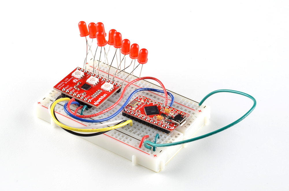
While chasing among the colors of the RGB LEDs is colorful, it doesn't lend the sense of motion that we'd expect from an LED scanner. For a more traditional look, we cut the jumpers to disable the onboard LEDs, and added a group of 9 red 5mm LEDs.
language:c
/******************************************************************************
Engines-scaner.ino
9-channel LED scanner using LP55231.

Byron Jacquot @ SparkFun Electronics
October 21, 2016
https://github.com/sparkfun/SparkFun_LP55231_Arduino_Library

Using output maps for the execution engine, sequentially cycles through the 9
LED outputs, resulting in a scrolling pattern.  See the LP55231 breakout board
hookup guide for a  detailed examination of how this works.

Resources:
Written using SparkFun Pro Micro controller, with LP55231 breakout board.

Development environment specifics:
Written using Arduino 1.6.5

This code is released under the [MIT License](http://opensource.org/licenses/MIT).

Please review the LICENSE.md file included with this example. If you have any questions
or concerns with licensing, please contact techsupport@sparkfun.com.

Distributed as-is; no warranty is given.
******************************************************************************/


#include <Wire.h>

#include <lp55231.h>

static const int32_t enable_pin = 15; // Apparently active high?
static const int32_t trigger_pin = 14; // low if unused
static const int32_t interrupt_pin = 16;

static uint32_t next;

static Lp55231Engines ledChip(0x32);

static const uint16_t program[] =
{
    0x9c10, // 0 map start
    0x9c9f, // 1 map end
    0x06ff, // 2 ramp up
    0x0200, // 3 wait
    0x07ff, // 4 ramp down
    0x9d80, // 5 map next
    0xa002, // 6 loop to 2
    0x000a, // 7 - empty placeholder
    0x0005, // 8 - empty placeholder
    0x000a, // 9 - empty placeholder
    0x0005, // a - empty placeholder
    0x000a, // b - empty placeholder
    0x0005, // c - empty placeholder
    0x000a, // d - empty placeholder
    0x0005, // e - empty placeholder
    0x000a, // f - empty placeholder
    0x0001, // 10 map begin - start of 2nd page
    0x0002, // 11
    0x0040, // 12
    0x0004, // 13
    0x0008, // 14
    0x0080, // 15
    0x0010, // 16
    0x0020, // 17
    0x0100, // 18
    0x0020, // 19
    0x0010, // 1a
    0x0080, // 1b
    0x0008, // 1c
    0x0004, // 1d
    0x0040, // 1e
    0x0002, // 1f  map end
};


void setup()
{
    Serial.begin(9600);

    delay(5000);
    Serial.println("### Setup entry");

    pinMode(enable_pin, OUTPUT);
    digitalWrite(enable_pin, LOW);
    digitalWrite(enable_pin, HIGH);

    ledChip.Begin();
    ledChip.Enable();

    // Chip needs a moment to wake up.

    delay(1000);

    ledChip.ClearInterrupt();

    for(uint8_t i = 0; i < 9; i++)
    {
        ledChip.SetLogBrightness(i, true);
        ledChip.SetDriveCurrent(i, 0xff);
    }

    if(ledChip.LoadProgram(program, (sizeof(program)/2)))
    {
    Serial.println("Program loaded?");

        if(ledChip.VerifyProgram(program, (sizeof(program)/2)))
        {
            Serial.println("program verifies");
        }
    }
    else
    {
        Serial.println("Program dodn't load?");
    }

    next = millis() + 3000;

    ledChip.SetEngineEntryPoint(0, 0);
    ledChip.SetEnginePC(0, 0);

    ledChip.SetEngineModeFree(0);
    ledChip.SetEngineRunning(0);

    Serial.println("### Setup complete");

}

void loop()
{
int32_t result;
int8_t  val;
static uint32_t count = 0;

    if(millis() >= next)
    {
        next += 1000;
        count++;

        Serial.print("# ");
        Serial.println(count);

        Serial.print(ledChip.GetEnginePC(0));
        Serial.print(" ");
        Serial.println(ledChip.GetEngineMode(0));

    }
}
Load the sketch above, and observe that the LEDs chase from side to side.
Theory Of Operations
Let's dissect the sketch a little, and examine a couple of the finer points. We'll read it in reverse, starting at the bottom, and working out way to the top.
First, note what's going on in loop()
language:c
 void loop()
{
    static uint32_t count = 0;

    if(millis() >= next)
    {
        next += 1000;
        count++;

        Serial.print("# ");
        Serial.println(count);

        Serial.print(ledChip.GetEnginePC(0));
        Serial.print(" ");
        Serial.println(ledChip.GetEngineMode(0));
    }
}
It's not doing anything that specifically makes the LED scanner run! It checks the program counter, but doesn't do anything that makes LEDs illuminate. After initialization, all of the LED scanning work is being done independently by the LP55231. This means that the microcontroller is completely available for other tasks.
The tradeoff of avoiding computational load in loop is that the initialization is much more detailed. setup contains the following lines.
language:c
...
ledChip.Begin();
ledChip.Enable();

// Chip needs a moment to wake up.

delay(1000);

ledChip.ClearInterrupt();

for(uint8_t i = 0; i < 9; i++)
{
    ledChip.SetLogBrightness(i, true);
    ledChip.SetDriveCurrent(i, 0xff);
}
if(ledChip.LoadProgram(program, (sizeof(program)/2)))
{
    Serial.println("Program loaded?");

    if(ledChip.VerifyProgram(program, (sizeof(program)/2)))
    {
        Serial.println("program verifies");
    }
}
else
{
    Serial.println("Program dodn't load?");
}

next = millis() + 3000;

ledChip.SetEngineEntryPoint(0, 0);
ledChip.SetEnginePC(0, 0);

ledChip.SetEngineModeFree(0);
ledChip.SetEngineRunning(0);
...
This Sequence of commands:
- Initializes the IC (
BeginandEnable) - Loads and verifies the execution engine program (
LoadProgramandVerifyProgram). We'll examine the program more closely in a moment. - Instructs the LP55231 to execute the program (
SetEngineEntryPoint,SetEnginePC,SetEngineModeFreeandSetEngineRunning).
The actual scanner is written in LP55231 machine language, contained in the program array:
language:c
static const uint16_t program[] =
{
    0x9c10, // 0 map start
    0x9c9f, // 1 map end
    0x06ff, // 2 ramp up
    0x0200, // 3 wait
    0x07ff, // 4 ramp down
    0x9d80, // 5 map next
    0xa002, // 6 loop to 2
    0x000a, // 7 - empty placeholder
    0x0005, // 8 - empty placeholder
    0x000a, // 9 - empty placeholder
    0x0005, // a - empty placeholder
    0x000a, // b - empty placeholder
    0x0005, // c - empty placeholder
    0x000a, // d - empty placeholder
    0x0005, // e - empty placeholder
    0x000a, // f - empty placeholder
    0x0001, // 10 map begin - start of 2nd page
    0x0002, // 11
    0x0040, // 12
    0x0004, // 13
    0x0008, // 14
    0x0080, // 15
    0x0010, // 16
    0x0020, // 17
    0x0100, // 18
    0x0020, // 19
    0x0010, // 1a
    0x0080, // 1b
    0x0008, // 1c
    0x0004, // 1d
    0x0040, // 1e
    0x0002, // 1f  map end
};
The program breaks down into 4 sections, marked with line numbers in the comment column. Let's review the sections, starting from the bottom
- Lines
10through1fare the output mapping table. Each line in the table specifies a single LED. The table is 16 lines long -- 9 lines to scan form 1 to 9, then 7 more lines from 9 back down to 1. - Lines
0and1specify the start and end of the mapping table. As the program runs, it increments through the table. When it reaches the end, it starts over from the beginning. - Lines
7tofare unused. Developing the program, there's less to keep track of if there's a little room for the program to grow or shrink, without having to move the mapping table and remember to adjust the table mapping instructions. - Lines
2to6are the actual program. It fades in, pauses a moment, then fades out, selects the next output, and loops back to the beginning.
More Engine Information
If you're working with the execution engines, you'll probably find that the LP55231 datasheet seems a little short. The LP55231 has a cousin in the LP8501 which is very similar. It's a tiny BGA part, but the datasheet is more detailed, particularly pages 19 through 25, that explain the instruction set more clearly, and give an example of setting the engine to run a program.
We've also got a number of examples showing off various features -- check the github repo. As we explored the features of the LP55231, we kept sketches to demonstrate them. Each sketch starts with a comment that describes what it's doing.
Texas Instruments also have a Windows assembler application to assist in writing LP55231 programs. You can find it in the tools & software section of the LP55231 webpage. We started out using it, but quickly learned to write LP55231 programs from scratch, in hexadecimal.
A Few Notes On using The Execution Engines
Things we've learned through trial and error.
- Each engine calculates a single output value. To drive multiple LEDs from a single engine, you need to use mapping tables.
- The
Lp55231Engineslibrary has routines to read the program counter and output mapping bits of each engine. These can be very useful when troubleshooting engine behavior. An engine that's not running will never change it's PC, and an engine without a mapped output, won't do anything visible. - If multiple engines map the same output, the lower-numbered engine controls the LED.
- All three engines have to be idle before program memory is accessible. The
Lp55231Enginesclass will force the engines into this state as part of theLoadProgramcall. In other words: loading and running are mutually exclusive. - There's an error in the datasheet: It transposes the
INTandENDnames in table 6. The instruction 0xd000 executes as an interrupt.