LP55231 Breakout Board Hookup Guide
Chip Internals
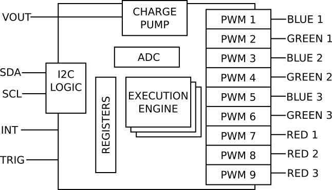
For an apparently tiny chip that simply illuminates LEDs, the LP55231 has a lot inside. Before we get into the example projects, lets take a peek under the hood.
Host Microcontroller Interface
The chip has 118 registers on the I2C bus, divided into several sections.
- The first group of registers is used for basic control of the chip. This includes power-up and reset functionality, as well as features such as charge-pump control and onboard diagnostics that can detect open or shorted LED outputs.
- Increasing in sophistication over the basics, the chip offers direct control over the LEDs. They can be turned on and off, output drive current can be set, and groups of LEDs can be controlled together using master faders.
- Finally, there are the execution engines. Their register interface includes random-access memory that holds the program, and registers that control when and how they run. We'll cover these in much greater detail shortly.
Charge Pump
The charge pump is a power supply that boosts the input voltage to a higher level.
Green, blue and white LEDs all have forward voltages in the 3.4VDC range. On a system powered from a 3.3V supply, they won't light up, so the LP55231 uses the charge pump to create a higher voltage to get those LEDs to turn on.
The charge pump is only used for the first six outputs -- the other three all use the system voltage. Channels 7, 8 and 9 are intended to drive red LEDs, which have a forward voltage around 2 volts, so they have no problem operating from a 3.3V supply. This also means that when driving RGB LEDs, the red, green, and blue channels aren't adjacent.
The IC enables the charge pump automatically when it detects that the system voltage is in the 3.3V range. With a 5V power supply, the charge pump is bypassed, and the 5V supply is used for all LEDs.
Output Drivers
The LED output drivers are Pulse Width Modulation outputs. They are highly configurable, with many options determining how they drive the outputs.
First, they are current-source outputs, configurable to match the attached LEDs, to a maximum of 25.5 mA per output. The output current is set per-channel by writing the corresponding current control registers.
Each output can also be configured to a logarithmic brightness response curve. Our eyes preceive light on a logarithmic scale, so the log mode allows the chip to fade in and fade out in a more visibly obvious manner. The tradeoff is that log mode doesn't achieve the brightest overall response.
Outputs can be grouped together using master fader channels. By assigning outputs to a master fader, the host microcontroller can control many LEDs with a single write operation. Master faders are also useful for fading mixed colors. The intensity of a mixed color can be controlled, without causing the color to shift as it fades.
Execution Engines
The crowning features of the LP55231 are the three execution engines. These are simple computers that perform LED-specific operations. They can set outputs to specific values, perform timed operations like blink and fade sequences, and respond to logic signals.
The engines are programmed using a simple machine language, which is loaded into memory over I2C.
The execution engines are powerful, but also cryptic. We'll demonstrate a program in the Execution Engine example, and there are demonstrations of more advanced features in the GitHub Repository.
One Thing Missing
The notable thing the LP55231 is lacking is non-volatile storage -- it doesn't have ROM or FLASH memory that would allow it to remember what it was doing across a power-cycle. As such, it works best as a peripheral to a microcontroller, rather than as a stand-alone device.
