LoRaWAN with ProRF and The Things Network
What is LoRaWAN?
If you're interested in the Internet of Things, you've probably heard of LoRa™ radios. LoRa™ is a fancy new kind of FSK (Frequency-shift keying) modulation that was developed by Semtech Corporation, it's short for Long Range and it lives up to the name.
Because LoRa™ is just a modulation scheme, it can be used anywhere that you would use other types of packet radio. In fact, one of our favorite LoRa™ modules — the HopeRF RFM95W — is a direct drop-in replacement for their standard FSK radio module — the RFM69HCW — which makes it easy to upgrade your existing packet radio projects to take advantage of Semtech's long-range, low-power technology.
One particular use of LoRa™ is uniquely exciting, though: LoRaWAN™
LoRaWAN™ is a network standard developed and maintained by the LoRa Alliance: an open association of collaborating members — mostly large tech companies — that's designed to allow low-power devices to connect to each other and the internet using public gateways. The standard dictates that devices can move freely between gateways. Essentially, it's like cellphone towers for IoT. The difference is that anyone can inexpensively own and operate a LoRaWAN™ gateway, so building the network is easy. And because anyone could theoretically operate a network server, it's relatively resistant to monopoly.
The LoRa Alliance has laid out a template for LoRaWAN™ networks and this template consists of 4 parts:
- Nodes
- Gateways
- Network Servers
- Application Servers
Nodes
A LoRaWAN™ node is an endpoint device, such as a sensor or an actuator of some kind. A node can be up to 10km (6 miles!) away from a gateway in ideal conditions with the right radio modules. The connection between a node and a gateway is very low bandwidth — between 0.3 and 50 kbps — but it is bi-directional. Nodes need to be smart enough to encrypt and decrypt packets, handle network authentication and respect the duty cycle (we'll talk about that in a minute) but these are tasks that can be easily achieved on super low-cost microcontroller hardware. The only other thing that a node needs to have is a LoRa™ radio and some kind of antenna.
Gateways
A LoRaWAN™ gateway — sometimes called a concentrator — is kind of like a cross between a cell tower and a WiFi router. It's the bridge between the nodes and the internet. Because of the long range capabilities of LoRa™, a single gateway can theoretically service entire cities or hundreds of square kilometers. Ideally, however, a given node will be "heard" by multiple gateways to ensure the best network fidelity. Nodes don't intrinsically know when they've been "heard" they just scream into the void, so it's always good to have multiple gateways within range. If multiple gateways happen to get copies of the same packet, that will be taken care of upstream at the network server. Besides range, another limitation to any LoRaWAN™ gateway is the number of channels it has. The number of channels that a gateway has is the number of nodes that it can talk to at once. At first, this seems extremely limiting since many consumer gateways are around 8 channels, but then we introduce the concept of duty-cycle.
Nodes agree to adhere to a duty cycle limitation. This limitation is actually enforced by government regulation in many parts of the world in an effort to keep the airwaves open for everyone to use. A duty cycle is a measure of the fraction of time that a resource is in use. For instance, if you're transmitting on a particular frequency for 2 seconds straight every 10 seconds, you're operating at a 20% duty cycle. So what's the duty cycle limitation for a LoRaWAN™ node? It depends on your local laws, but it's probably 1%. For certain applications it may be as low as 0.1%, but this isn't as low as it sounds. A 1% duty cycle represents almost 15 minutes of combined airtime per day, which far exceeds the fair usage policy of most free networks. And when you consider that a packet takes tens of milliseconds of airtime, these restrictions feel a lot more permissive. Also, by adhering to this duty cycle, we increase the number of nodes that can be serviced by a single gateway by a hundred times!
Network Servers
LoRaWAN™ nodes don't know anything about the internet so the gateway can't just turn LoRaWAN™ packets loose on the web and hope for the best. There needs to be a particular server that expects those packets and knows how to deal with them. This is the network server and — as the control center of the network — it has a lot of jobs to do. Its primary job is to direct packets between gateways and application servers. Since LoRaWAN™ allows for uplinks (messages to a server from a node) and downlinks (messages to a node from a server). Because the network server controls all gateways on the network, there are a lot of packets to juggle.
Another thing that the network server does is to de-duplicate packets coming in from multiple gateways. Since any node might be within range of multiple gateways and there's no hand-off when moving between them, the packets just get duplicated as each gateway sends its copy to the network server. The network server compares them and throws out identical packets. Finally, depending on the capabilities advertised by the network operator, a network server might be doing all kinds of other things like monitoring airtime usage and managing subscriptions. Some networks even offer localization for all nodes, triangulating them using "Differential Time of Arrival" techniques with multiple gateways.
The big thing to remember about the network server is that it does all of the behind-the-scenes work that makes a LoRaWAN™ network operate. Just like in the early days of cellular networks, not all gateways talk to the same network. LoRaWAN™ is only a network standard, not a network in and of itself. On top of this, the network server probably isn't going to run any application-specific code to talk to your devices, but it will know where to send your packets so that your application-specific code can see them...
Application Servers
An application server is a server that's connected to the network server (usually somewhere on the internet) that knows specifically what to do with packets from a given node or type of node. For instance, if you have a website that shows the current weather conditions at a certain LoRaWAN™ weather station, the weather station is sending packets which are being relayed to the network server by one or more gateways. The network server isn't interpreting that weather data or serving you the website... that stuff is happening on an application server. The application server and the node are both registered with the network server, so it knows to send packets from the weather station node to the weather station application server. Application servers can be anything from an IFTTT Webhook to a Raspberry Pi somewhere on the web. Sometimes an application server makes data available to browsers, sometimes it simply manipulates data and sends it back out to nodes over the network server.
"Okay, So How Do I Get In On This?"
There are a lot of LoRaWAN™ networks all over the world, some free to use and some paid. The largest free network today seems to be The Things Network, and it's growing every day. Even if you're not currently covered, you can set up your own gateway and join the network to help it grow!
The Things Network
"Building A Global Internet of Things Network Together."
The Things Network is essentially the free, community-based, open source arm of The Things Industries — an integrated chain of products and services for developing enterprise IoT solutions. While The Things Industries makes their money selling hardware, software, services and consulting, they maintain The Things Network as a sort of tech demo and a tool for gaining market share. I know this is a cynical way to discuss a free open source network, but I like to put it in these terms because their service is so convenient and well maintained that it's natural to wonder, "what's the catch?"
The Things Network (TTN) is a LoRaWAN™ network server with some extra bells and whistles. Registering a node or an application to the network is free and so is the network traffic — as long as you follow the fair use guidelines. Services are based on best effort, so there's no guarantee on uptime or latency, but it's free! The Things Network also encourages members to grow the network by making it incredibly easy to register a gateway. Simply connect your gateway hardware to the internet, open the TTN console, and follow the prompts. They sell their own branded gateway hardware, but they also provide documentation for registering your homebrew gateway. When you register a gateway, you also provide your gateway's physical location and antenna placement so The Things Network can estimate network coverage and map that coverage for potential users.
To help grow the network, The Things Network even provides resources for finding, joining and starting regional "communities," organizations dedicated to providing an entire city or area with network coverage. You can see a map of existing communities in the button below. Many large cities around the world already have total coverage!
Needless to say, we think The Things Network is a pretty cool idea. Also, since it's free, it's a great way to get started with LoRaWAN™. We'll be using The Things Network to complete this tutorial, so if your city doesn't have TTN coverage, you'll need to set up a gateway of your own. You can buy one from The Things Network Marketplace or make your own with an ESP8266 or a Raspberry Pi!
Registering Your Node
Before you can program your first node, you'll need to register a device on The Things Network. Registering allows the network to generate the necessary keys which you'll then place in your code so that the network recognizes your device.
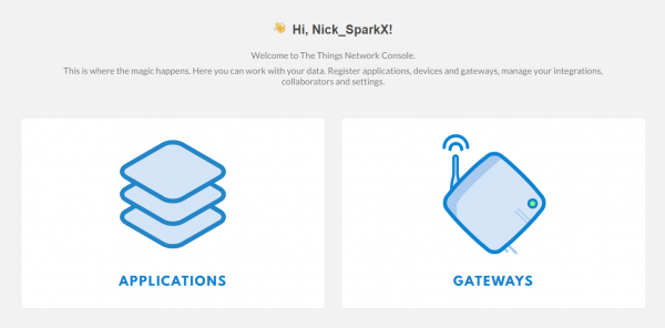
Once you've logged into the console, you'll be presented with a screen like this:
You'll notice that there's no option to just add a node, that's because The Things Network needs to know what application to associate with your device. Therefore, you'll need to start by creating an application. Clicking on the Applications button will take you to a page that looks like this:
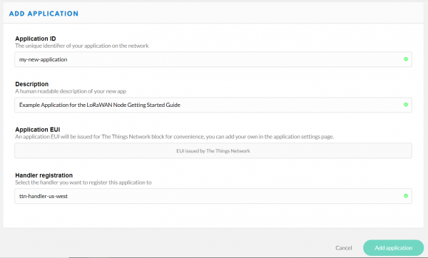
This would usually be a list of all your applications, but The Things Network very helpfully recognizes that you don't have any applications yet and suggests that you add one. You can add an application either by clicking that link or clicking on "add application" in the upper right corner. Both of those links will take you to this page:
Give your application an Application ID; this is the name that The Things Network will use to distinguish it from the other applications. It can only contain lowercase letters, numbers, and dashes. The description field is for humans, so take a moment to write a sentence about what your app does. In this case, I've just written that it's an example application. The EUI will be issued by the network, so there's no need to type anything there. Finally, select the handler that you want your application to be registered to. Essentially, these are instances of the network server in different physical locations around the world. All applications will talk to all network servers, but to minimize latency, it's best to select the handler closest to your gateway. I'm in Colorado, so I chose "ttn-handler-us-west," which I assume is in California somewhere. Click the Add Application button and you'll be taken to your freshly generated application console.
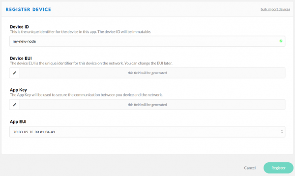
Now that you've created an application, you can register a device to it. Scroll down to the Devices section of the application page and you will see your current device count (which is none) as well as options to register a device and to manage devices. Click on register device.
This form is pretty similar to the Register an Application page, but you have a little less to do. Give your device a Device ID, the same rules apply as did with the Application ID. Then click the little crossed arrows beside the Device EUI field, this lets TTN know that you want them to generate an EUI for you. Now just click on the Register button at the bottom of the form.
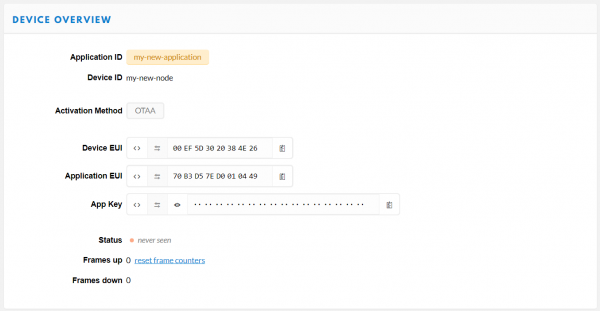
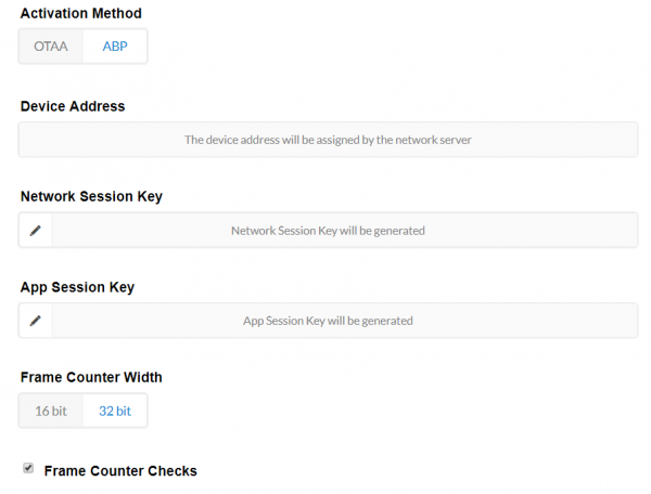
And now you've been taken to your brand new device console. Under the section labeled Device Overview you'll notice the Application ID and Device ID that you set earlier. Under Activation Method it will likely say "OTAA," which stands for Over The Air Activation. This is a secure, transportable method of activating LoRaWAN devices, whereby the device uses a known application key to request new session keys whenever it wants to join the network. This is the preferred method for activating a production device, but for prototyping it's usually easier to hard code the session keys into your device. In order to do this, we'll need to set the activation method to "ABP" or Activation By Personalization. To do this, click on the Settings tab in the upper right-hand corner of the device page and you'll be taken to the device settings menu. Partway down the page you should find an option to change the activation method.
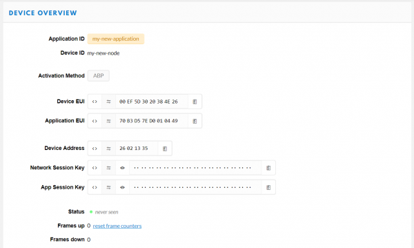
Click on "ABP," and then save your settings. When you return to the Overview page, you should now see some extra fields in the Device Overview:
We'll need these numbers to program your Pro RF so leave this page up on your browser and let's open up the Arduino IDE. It's time to program the node!
Programming Your Node
Note: This example assumes you are using the latest version of the Arduino IDE on your desktop. If this is your first time using Arduino, please review our tutorial on installing the Arduino IDE. If you have not previously installed an Arduino library, please check out our installation guide.
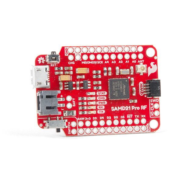
We developed the Pro RF to be a small, lightweight LoRaWAN™ node. All you need to do is close two solder jumpers on the bottom of the board (labeled LoRaWAN™) to connect the extra GPIO required by the LoRaWAN™ library. With that done, let's get started!
Get the LMIC-Arduino Library
For this example, we're going to use a library written by Matthijs Kooijman which is a modified version of "IBM's LMIC (LoraMAC-in-C)" library. You can download it through the Arduino Library Manager. It's currently called "IBM LMIC Framework" in the Arduino Library Manager, but that may change to "LMIC-Arduino" in the next release. Or you can download and manually install it from the GitHub Repository.
Once you have the library installed, you may need to edit the LMIC configuration file. Find your Arduino libraries folder and navigate to ...IBM_LMIC_framework/src/lmic/, you should find a file called config.h here, open it in any text editor and find the lines where CFG_us915 is defined. It should look like this:
language:c
//#define CFG_eu868 1
#define CFG_us915 1
// This is the SX1272/SX1273 radio, which is also used on the HopeRF
// RFM92 boards.
//#define CFG_sx1272_radio 1
// This is the SX1276/SX1277/SX1278/SX1279 radio, which is also used on
// the HopeRF RFM95 boards.
#define CFG_sx1276_radio 1
Since we're using the 915MHz radio module, you need to make sure that the line #define CFG_us915 1 is not commented out and that the line #define CFG_eu868 1 is, by prepending // as shown above. Same goes for the radio type, we want #define CFG_sx1276_radio 1 and not #define CFG_sx1272_radio 1. With those changes made, save the config.h file and return to the Arduino IDE.
Edit the Example Code
With the library installed, you should now have the example code in your Examples menu. Let's start with File>Examples>IBM LMIC framework>ttn-abp, this is the "ABP" or "Activation By Personalization" example code. In order to make it work with your application you'll need to copy in some keys from the Device Overview page on your TTN Console, so flip back to the browser tab with the Device Overview page loaded up.
You'll notice that, by default, the Network Session Key and App Session Key fields are obscured for security reasons. You can click the eye icon to show the code before copying it. Also, it will be easier to copy this into the example code if you click the <> button to show the codes in "C style".
You will need to copy three separate numbers into your example code from this page: the Network Session Key, the App Session Key, and the Device Address. Here's a diagram explaining which field on this page corresponds to which constant in the example code:
You will also need to replace the pin mapping portion of the code, which correlates the pin definitions used by the lmic library with the physical connections on the Pro RF. Find the section labeled // Pin mapping and replace with the following:
// Pin mapping
const lmic_pinmap lmic_pins = {
    .nss = A5,
    .rxtx = LMIC_UNUSED_PIN,
    .rst = 4,
    .dio = {7, 10, 11},
};
With these constants replaced in your example code, you can upload it to your Pro RF and watch for data to come pouring in!
Watch for Data
The example code is designed to send the string "Hello, World!" once every minute. This is actually a pretty large string for LoRaWAN™ and you shouldn't allow the example code to run all day because it will eventually violate TTN's Fair Usage Policy. But don't worry too much about it, you can send a string the size of "Hello, World!" over 600 times in 24 hours before violating the policy.
To see the data arriving from your device, click on the Data tab in your device console. You should see a field labeled Application Data and after a minute or so, you'll hopefully see your first packet come through:
Congratulations! You just sent your first LoRaWAN™ packet to The Things Network, your node device is working!
Decoding Your Data
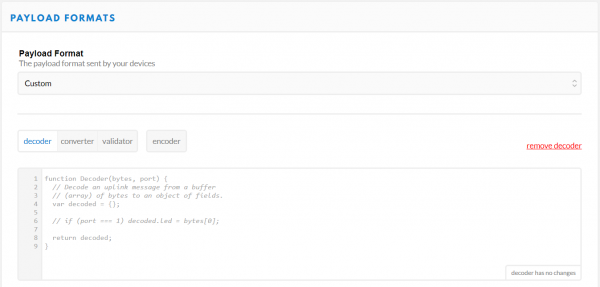
You may have noticed in the Application Data window that your payload is shown in raw bytes. In order to see "Hello, World!" encoded in ASCII, the way you sent it, you'll need to decode the payload. The Things Network includes tools for doing this right in the console! Navigate to the Application Overview page for your application and click on the Payload Formats tab. This menu allows you to write functions which will be applied to all incoming packets for this application.
So let's write our own decoder. We need to take the raw byte data and return a string that contains all of the characters corresponding to each byte. Take a look at this solution and then we'll walk through it:
language:js
function Decoder(bytes, port) {

return {
    ASCII: String.fromCharCode.apply(null, bytes)
};

}
Decoder is a Javascript function that The Things Network has already set up for us. It takes two arguments called bytes, an array containing our payload, and port, the LoRaWAN™ "FPort" of the packet. FPort identifies the end application or service that the packet is intended for. Port 0 is reserved for MAC messages. We don't need to know anything about the port number for our example.
We can return any value that we want from the Decoder function and it will appear alongside our payload in the Application Data window. In the example above, I've created a new property called "ASCII" which is equal to String.fromCharCode.apply(null, bytes). To break this down a little more, we're returning a new String object called "ASCII," and we're using the Javascript apply() method to call fromCharCode() with the argument bytes and stuff the result into our new String. The fromCharCode() method simply steps through each byte in the array bytes (which, remember, contains our payload) and returns the ASCII character represented by that character code.
After copying the above code into your decoder function, scroll down and click the save payload functions button. Now return to the Application Data window and you should see that all packets received after the decoder function was changed now have a new property:
Our packet has been decoded! Excellent!
Using Your Data
Okay, so now you have data coming in to your TTN application but what do you do with it? Well, you have a few options:
APIs
The most basic endpoints for interacting with The Things Network programmatically are the TTN Handler APIs or "application programming interfaces". There are two APIs, the Data API and the Application Manager API. The Data API allows you to send and receive messages, making it the most useful for most applications. You can interact with this API using the MQTT protocol. The Application Manager API is available directly through HTTP and lets you manage applications, gateways, and devices. It's much more powerful than the Data API and is mostly intended to allow endpoint applications to perform device management.
SDKs
The Things Network has also created several Software Developer Kits (SDKs) which allow you to program your application without having to interact directly with the low level APIs. SDKs are available for several popular languages.
Integrations
Finally, the easiest way to access your data and put it to work is with The Things Network's various platform integrations. Integrations allow you to pass your application data directly to another platform such as AWS IoT, Cayenne, EVRYTHNG, or IFTTT. From there, you can use those platforms to interact with your data.
Example: IFTTT Integration
As an example of how to use Integrations, let's set up an IFTTT integration with our example application.
If you've never used IFTTT, go ahead and create an account. IFTTT is a pretty cool platform that allows you to combine services from around the web to automate all kinds of tasks. These combinations of services are called "recipes" and they take the form of "If This happens, then make That happen," and in our case, the This will be new data arriving in our application. First, head over to your TTN Application Console and click on the Integrations tab and then click "add integration".
Find the "IFTTT Maker" integration in the list. It looks like this:
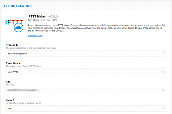
Clicking on that block will take you to the "Add Integration" form for this integration. The form has 6 fields:
Process ID -- This is a name that TTN will use to keep track of this integration. You can name it whatever you want, I'm calling mine "my-new-integration".
Event Name -- This is the name of the IFTTT "recipe" that you want to trigger whenever the application receives new data. Go ahead and name this something, just remember what you named it so we can call your IFTTT recipe the same thing.
Key -- This is your IFTTT Key. You can find this by going to the Maker Webhooks page on IFTTT and clicking on the Documentation button.
Value 1, Value 2, and Value 3 -- IFTTT Webhooks allow you to pass up to 3 values to your IFTTT recipe. In this case, let's pass our decoded payload to IFTTT. To do this, we put the name of the property that we want to pass into the Value field, so type "ASCII" into Value 1.
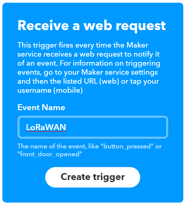
Alright, take note of the Event Name that you set, click the Add integration button and let's hop over to IFTTT. Get to the New Applet page and click on the +This in If +This Then That. You should now be looking at a list of all the services that IFTTT has triggers for... it's a lot. Click the "Webhooks" service and choose the Receive a Web Request trigger. This is where you'll enter the Event Name that we chose earlier when setting up the integration on TTN.
Click on Create Trigger and you'll be brought back to the Make an Applet page. Now click on +That to add an action for the trigger we just created. There are all kinds of triggers available for IFTTT, but let's do something simple for the purpose of this tutorial. Click on the Email service and select the Send Me an Email action. This will send you an email at the address that you used to sign up for IFTTT every time that new data comes in on your TTN application. You can even edit the body of the email. Notice that Value 1, Value 2, and Value 3 are ingredients in the email. Wherever you see that ingredient, it will be replaced with the appropriate value. In our case, Value 1 will be replaced with the value of ASCII. Click on Create Action and then Finish to start your new applet running.
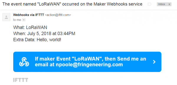
Now open up your email and plug in your Pro RF. After a few minutes, you should get an email from IFTTT!
Pretty. Darn. Cool.
Resources and Going Further
Now that you know all about LoRaWAN, how will you use it? There are a few hookup guides that can help you get started with the SparkX Pro RF - LoRa®-enabled 915MHz board. While support is limited for SparkX products, these should get you moving in the right direction.
- Pro Micro Hookup Guide
- RFM69 Hookup Guide - This is the hookup guide for the RFM69 breakout board. The RFM95W module used on the SparkX Pro RF - LoRa® enabled board is in essence a drop in for the RFM69 module with 2 additional GPIO pins to enable LoRa®. Also be aware that the two use different libraries.
Even more resources:
- The Things Network: LoRaWAN™
- LoRa Alliance™
- LoRa and Pycom
- The Things Industries
- LMIC-Arduino GitHub Repository
- IFTTT
- Wikipedia: Frequency-Shift Keying (FSK)
Need inspiration? Feel free to check out some of the following tutorials!
IoT Tutorials
SparkFun Inventor's Kit for Photon Experiment Guide
ESP8266 WiFi Shield Hookup Guide
Experiment Guide for the Johnny-Five Inventor's Kit
Getting Started with TJBot
Wireless Tutorials
Teensy XBee Adapter Hookup Guide
Logging Data to Google Sheets with the Tessel 2
Simultaneous RFID Tag Reader Hookup Guide
LoRaSerial Hookup Guide
Or check out this blog post for even more fun inspiration!
