LogicBlocks Experiment Guide
 jimblom
Logic Beyond LogicBlocks...
These experiments have barely covered the tip of the proverbial iceberg. We've discovered a lot of fundamental electronics building blocks, but there are many left to uncover. Unfortunately, with the standard kit we've run out of blocks. Here are a few of the foundational circuits and concepts we'd be remiss if we didn't discuss:
Adders
Adders are actual circuits (as opposed to the snakes) that add numbers, and they're built with logic gates! A half-adder is the most simple adder circuit there is. It adds two bits together and has two outputs: the sum (S) and a carry (C). As you can see, the circuit isn't all that complicated:
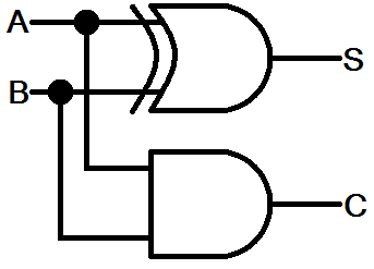
The sum of the two bits is just their XOR, and if both A and B are 1 we generate a carry output.
More complete adders, called full-adders, also have a carry input. These circuits can be strung together in long chains to create a multi-bit binary adder.
Most processors have a block of circuitry within them called an arithmetic logic unit (ALU), where all of the addition, subtraction, multiplication, and division operations are performed. The ALU houses hundreds of adder circuits (among others), and links them to create enormous 32- or 64-bit adders.
Flip-Flops (Latches)
We talked about flip-flops in the SR Latch experiment, but we only glossed over the importance of these circuits. The SR latch we made is one of the more simple latches in electronics. We can modify the SR latch to create a D latch:
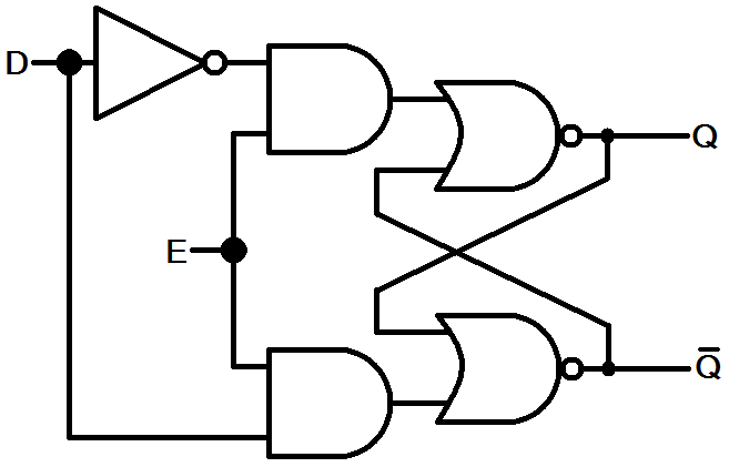
Notice the SR latch in there? The D latch has two inputs -- data (D) and enable (E). As long as the enable input is 1, the Q output will be whatever D is. If enable goes low, Q will retain its set value regardless of what the data input does.
Another popular latch is the JK latch. This latch is also based on the SR latch, but it modifies that "illegal" set of inputs (the one where Q and Q were equal) to instead toggle the current output. Here's how the JK latch is built:
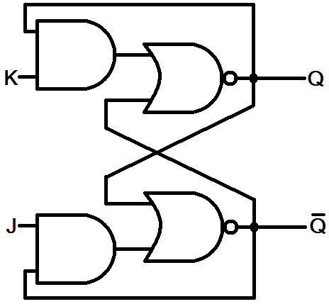
The truth table for a JK latch looks something like this:
| J | K | Previous Q | Current Q |
|---|---|---|---|
| 0 | 0 | 0 | 0 (hold state) |
| 0 | 0 | 1 | 1 (hold state) |
| 0 | 1 | X (don't care) | 0 (reset) |
| 1 | 0 | X | 1 (set) |
| 1 | 1 | 0 | 1 (toggle) |
| 1 | 1 | 1 | 0 (toggle) |
Now, let's turn that JK latch into a JK flip-flop. Flip-flops are usually created by adding a clock input to a latch. A flip-flop with a clock input will usually only perform an operation on the rising edge of a clock signal. The clock input can be used in many ways, for instance multiple flip flops can be synchronized by sharing a clock input. By replacing those 2-input AND gates with a 3-input variety, we can add a clock input to the JK flip-flop:
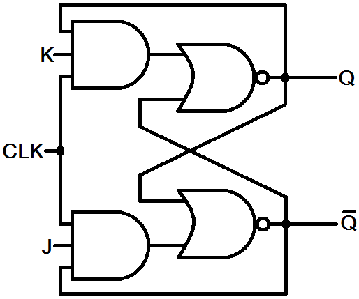
Now, the JK flop-flop will only produce a new output when the clock input is high. This gives us a bit more control over the operation of the flip-flop.
The JK flip-flop will come in handy in the next section...counters.
Counters
Adders add and counters count. Counters are a key element in most processors, especially in timing applications. Your digital clock has to count seconds somehow, right?
A really simple counter can be created by linking together numerous JK flip-flops. If multiple JK flip-flops are all set to constantly toggle (J=K=1), and we link the output of one flip-flop to the input of the next, we can create an asynchronous ripple counter. Here's how we might make a 3-bit ripple counter out of JK flip-flops:
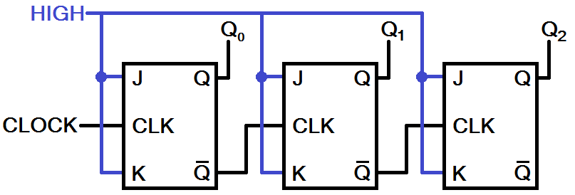
Q0, Q1, and Q2 are our three outputs; Q0 the least-significant bit, Q2 most. With three bits, this circuit can count all the way from 0 to 7 in binary. We can apply a periodic clock to the initial clock input, and begin the counting. Every rising edge on the clock leads to an increment on the counter. Since we've hooked up the complemented output from one JK to the clock input of the next, the Q outputs will toggle whenever the previous one falls.
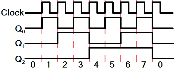
This 3-bit counter will overflow at 7, but adding more flip-flops will increase the upper limit by powers of 2 (n flip-flops count to 2n-1), so we'd need 20 flip-flops to count above 1 million.
There are other types of counters, but this is a good example built with logic circuits that aren't actually all that far-stretched from what we've learned so far.
7400 Series Logic Chips
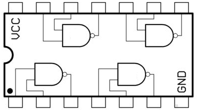
If you're looking for somewhere to go after LogicBlocks, we'd recommend looking into 7400 series logic chips. The 7400s are a huge range of integrated circuits (ICs) that implement all sorts of digital logic functions. You can find quad-NAND gates, along with a variety of other standard digital logic gates. In fact, the chips on the LogicBlock Gate blocks are 7400-series parts -- little single-circuit SMD versions.
Flip flops, counters, multiplexers, decoders, all sorts of other circuits we've covered in this tutorial are implemented in a 7400 series chip. Even more complicated circuits like entire 4-bit ALUs, memories, comparators...seriously, it's a pretty long list, check this out.
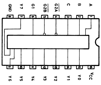
Most 7400 series chips come in a breadboard-friendly DIP package, like the 3-to-8 decoder below (74238). So you can experiment and explore without having to actually solder anything.
If you still can't get enough digital logic, CPLDs (compact programmable logic devices) or even FPGAs (field programmable gate array) would be the next step. They represent a giant leap in complexity from even the 7400 series chips, but those ICs can pack thousands of configurable digital logic circuits into a tiny space. There's a lot of digital logic out there for you to explore, but I hope the LogicBlocks have been a good introduction.