LogicBlocks Experiment Guide
 jimblom
8. 1-to-2 Decoder (De-Multiplexer)
The opposite of a multiplexer is a de-multiplexer, also called a demux or decoder. A demux allows a single input line to be passed through to multiple output lines, again using a select line to choose which output the input goes to.
The schematic for a 2-to-1 demultiplexer looks like this:
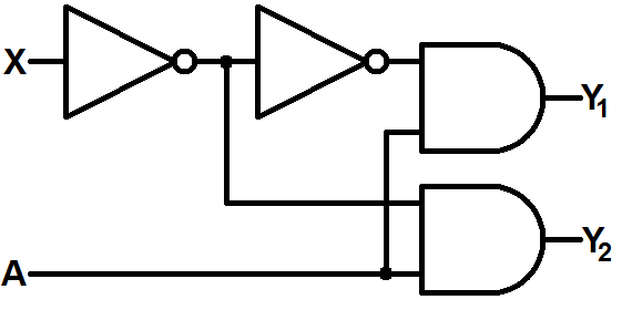
There are two inputs (X and A) and two outputs Y1 and Y2. X is our selector input, it decides which of the two outputs the A input is routed to. When X is 0, the output at Y2 mirrors A (while Y1 will always be 0). When X is 1, the A input is routed to Y1.
The demultiplexer becomes really handy when we have limited outputs available in our system and we need to interface with many many input devices.
What You'll Need
- 2x AND Blocks
- 2x NOT Blocks
- 2x Input Blocks
- 2x Splitter Blocks
- 1x Power Block
- 1x Feedback Cable
LogicBlocks Layout
Construct the LogicBlocks circuit as shown below. Use the feedback cable to simply extend the output of one splitter (you'll need to fuss with it a bit to fit it into both blocks).
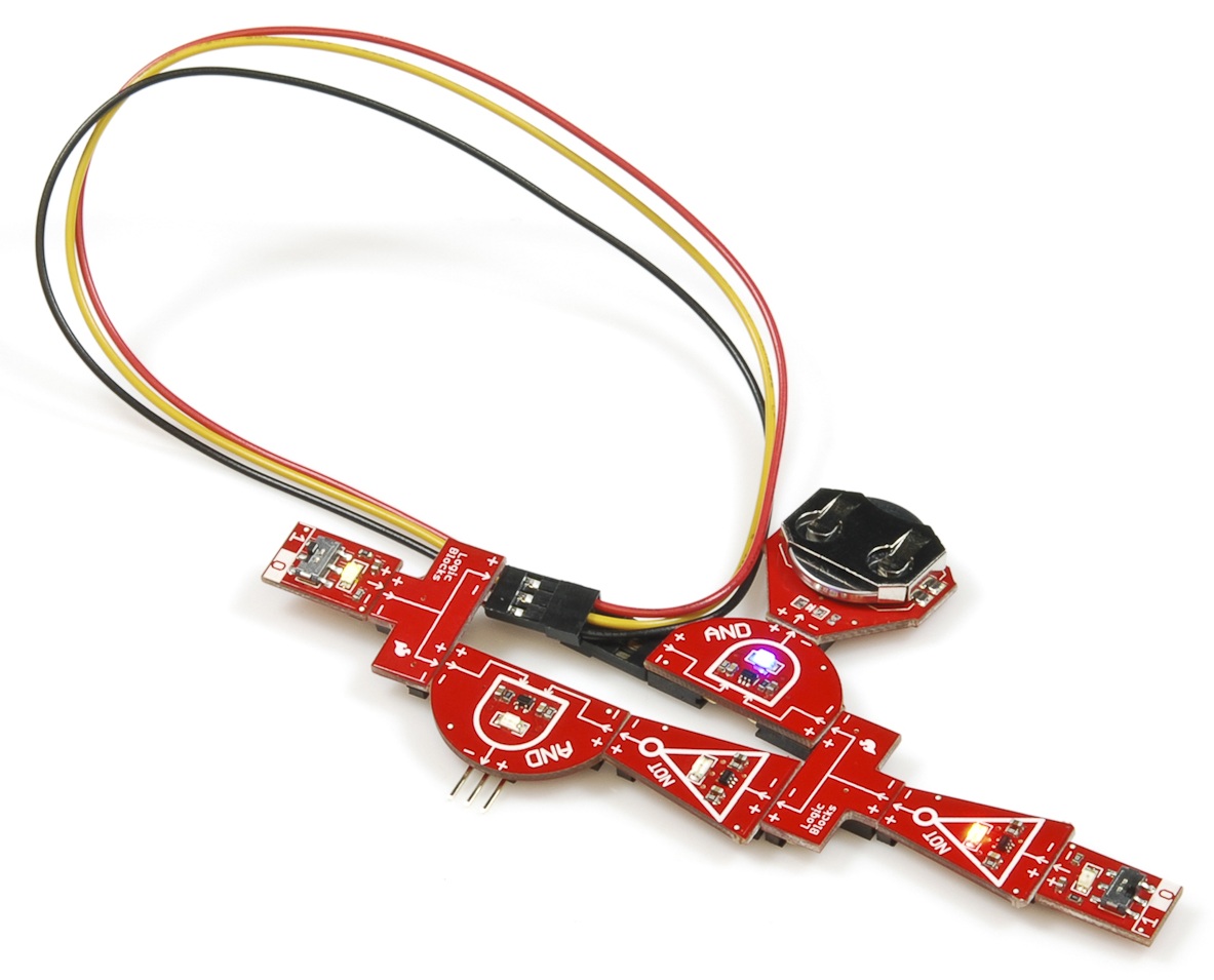
In this LogicBlock circuit, our selector input (X) is represented by the Input Block that runs into the NOT Block. The only remaining input is our A input.
The two outputs are each represented by the blue LEDs on each of the AND gates. Y1 is the AND Block without the Power Block attached.
The Experiment
Give this order of operations a try:
- Flip the selector input (X) to 0. Then try toggling the A input both high and low. Only one of the AND Blocks should change, and it should be the same value as the input.
- Flip the X input to 1. Again toggle A a few times. Now the other AND gate should be keeping pace with A.
- Can you imagine what a larger demux might look like? Here's an example circuit for a 2-to-4 decoder:
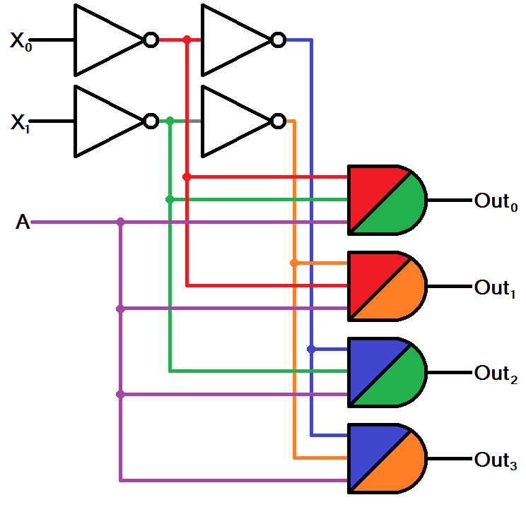
This circuit has two selector inputs (X0 and X1) which route our input (A) to one of the four outputs.
- Compare the 2-to-4 decoder to a 4-to-1 multiplexer (from the last experiment). How do they differe?
- Can you imagine what a circuit for a 3-to-8 decoder might look like?