LogicBlocks Experiment Guide
 jimblom
 7. 2-to-1 Multiplexer
A multiplexer (or mux) is a common digital circuit used to mix a lot of signals into just one. If you want multiple sources of data to share a single, common data line, you’d use a multiplexer to run them into that line. Multiplexers come in all sorts of shapes and sizes, but they’re all made out of logic gates.
Every multiplexer has at least one select line, which is used to select which input signal gets relayed to the output. In a 2-to-1 multiplexer, there’s just one select line. More inputs means more select lines: a 4-to-1 multiplexer would have 2 select lines, an 8-to-1 has 3, and so on (2n inputs requires n select lines).
Think of a mux as a "digital switch". The select line is the throw on the switch, it chooses which of the many inputs get to be the output.
Here’s how you might make a 2-to-1 multiplexer out of logic gates. A and B are the two inputs, X is the select input, and Y is the output.
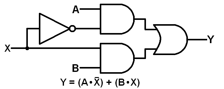
Here's what a truth table would look like for such a circuit:
| Select Input (X) | Input A | Input B | Output Y |
|---|---|---|---|
| 0 | 0 | 0 | 0 |
| 0 | 0 | 1 | 0 |
| 0 | 1 | 0 | 1 |
| 0 | 1 | 1 | 1 |
| 1 | 0 | 0 | 0 |
| 1 | 0 | 1 | 1 |
| 1 | 1 | 0 | 0 |
| 1 | 1 | 1 | 1 |
LogicBlock time!
What You'll Need
- 2x AND Blocks
- 1x OR Block
- 1x Inverter Block
- 1x Splitter Block
- 3x Input Blocks
- 1x Feedback Cable
- 1x Power Block
LogicBlocks Layout
Follow the layout below to create a 2-to-1 multiplexer (Hint: pay more attention than we did to matching up the + and − labels!):
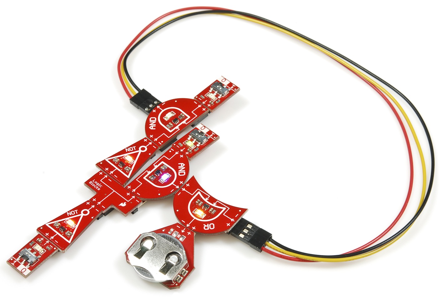
We'll need to internally label each of the inputs. The selector input (X) is the lonely input running into the NOT gate. The remaining two inputs are our A and B, which you can arbitrarily name as you wish.
The output of this multiplexer is indicated by the yellow LED on the OR gate.
The Experiment
Give this order of operations a try:
- Initial state: set all three inputs to 0. The output should be 0.
- Flip A to 1. Nothing should happen to the output, since, with the selector switch set to 0, the B input is being fed into the output.
- Toggle the B input to 1. Observe the output, and set B back to 0. The output should follow your toggling on B!
- Switch the selct to 1. The output should now follow the A input, and it won't care what B is set to.
- Is this circuit combinational or sequential? (Don't let the "Feedback" cable fool you!)
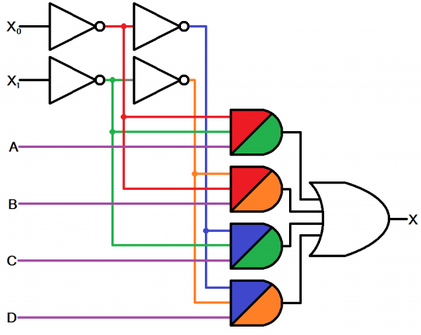
- Can you imagine what a 4-to-1 multiplexer might look like? It'd require double the inputs lines -- two selectors and four possible inputs. Here's a (color-coded) schematic for a 4-to-1 multiplexer:

A 4-to-1 demux requires four 3-input ANDs, four NOTs, and one 4-input OR. This circuit allows us to choose to send either A, B, C, or D into the X output. X0 and X1 do the selecting.
- How many gates do you think a 8-to-1 multiplexer might require?