LogicBlocks Experiment Guide
 jimblom
5. Ring Oscillator
An oscillator is a circuit whose output periodically and repetitively fluctuates. Oscillators are a critical part of most electronic circuits; they're used to create anything from a clock to radio waves. There are a variety of circuits that can create oscillation, you can use op amps, crystals, 555 timers, and, of course, logic gates!
By stringing an odd number of NOT gates together, and introducing feedback -- looping the output of the last inverter back to the input of the first -- we can create a ring oscillator. Let's LogicBlock it!
What You'll Need
- 3x NOT Blocks
- 1x Splitter Block
- 1x Feedback Cable
- 1x Power Block
Circuit Diagram
This circuit introduces a concept we've only briefly mentioned so far: sequential circuits. Unlike combinational circuits, the output of a sequential circuit depends on previous output states.
Here is the circuit for a ring oscillator:
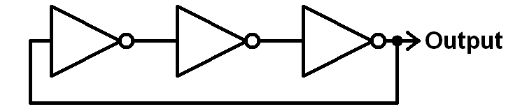
See how the output of third and final NOT gate splits into two directions? The first goes straight out to the output, like we're used to, but it also loops back into the input of the the first NOT gate. This is called feedback -- a term almost synonymous with sequential circuits. The current state of the output depends on what it was doing in the past.
LogicBlock Layout
First link up three NOT gates and plug the third into a Splitter Block. Use the Feedback Cable to connect one of the Splitter Block outputs to the input of the first NOT gate. Finally, plug the Power Block into the second output of the Splitter Block.
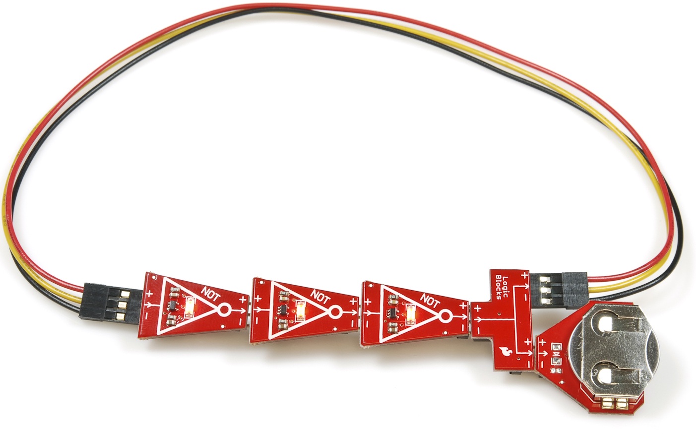
The output of this circuit is represented by the red LED on the third and final NOT block.
The Experiment
What does the truth table look like for this circuit? Wait. Does it even have a truth table? There aren't any inputs! Instead of a standard truth table, we can create a state table that defines the value of the current output as dependent on the previous output:
| Previous Output | Current Output |
|---|---|
| 0 | 1 |
| 1 | 0 |
- Does the number of inverters have to be odd? What happens if there are an even number of inverters? Try removing one of them.
- Can you calculate how fast the LED on the final NOT Block is blinking? Each block has a delay of about 1 second. What effect would increasing the number of inverters to 5 have on the blinking rate of the output?
Sub-Experiments
In some cases it may be handy to have an enable input on your oscillator. Enable inputs -- commonly found in many digital logic circuits -- control the overall operation of the circuit. When the enable input is set to 1, the circuit operates as normal, but when its set to 0 the circuit's operation is halted.
We can add an enable input to the ring oscillator by introducing an AND gate. Have a look at this circuit diagram:
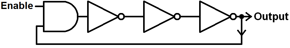
Build it by plugging an AND Block into the first NOT gate (removing the feedback cable). Then plug the male end of the feedback cable into one of the AND Block's inputs, and an Input Block (our enable) into the other input.
Now flip the switch on the enable input to see how it affects the output of the oscillator.
What would the state table look like now?
| Enable | Previous Output | Current Output |
|---|---|---|
| 0 | 0 | |
| 0 | 1 | |
| 1 | 0 | |
| 1 | 1 |