LogicBlocks Experiment Guide
 jimblom
6. SR Latch
A latch (also called a flip-flop) is a fundamental component of data storage. A single latch can hold 1-bit of data, increase that number by many orders of magnitude and you can create kilo-, mega-, giga-, even tera-bytes of memory. Of course, like most digital circuits, latches are made out of digital logic gates!
There are many different kinds of latches, all with somewhat cryptic names like SR, D, JK, and T. The SR-latch we'll be experimenting with is one of the most fundamental forms of a latch.
There are a few ways to make an SR latch. Here’s an example of a NOR SR latch:
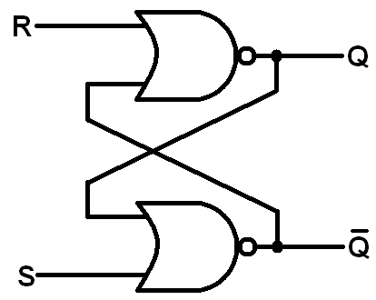
Notice the feedback? This is another sequential logic circuit. The two NOR gates each have their output flow into the input of the other. There are two controllable inputs: reset (R) and set (S), which produce the two outputs: Q and Q ("Q-not"). That's where the SR latch get's its name -- it's a set/reset latch.
The SR latch comes with a rule, which cannot ever be broken: Q must always be the opposite of Q. These outputs are called complements. In our application Q is the only output we really care about -- that's where the latch's data is usually stored and retreived -- but it's important to observe that the two outputs are opposites.
An SR latch is so important it even gets its very own circuit symbol:

Here is the state table, which is a bit wonky. Because the circuit is sequential, the current value of Q depends on its previous state:
| S | R | Previous Q | Current Q | Current Q |
|---|---|---|---|---|
| 0 | 0 | 0 | 0 (no change) | 1 |
| 0 | 0 | 1 | 1 (no change) | 0 |
| 0 | 1 | 0 | 0 (no change) | 1 |
| 0 | 1 | 1 | 0 | 1 |
| 1 | 0 | 0 | 1 | 0 |
| 1 | 0 | 1 | 1 (no change) | 0 |
| 1 | 1 | 0 | 0 (Restricted, Q and Q would not be complements) | 0 |
| 1 | 1 | 1 | 0 (Restricted, Q and Q would not be complements) | 0 |
Put into words, the output, Q, can be in any of the following states:
- Steady: When S and R are both 0, then Q remains steady. It keeps the value it had before. If it was 0 it'll remain 0, if it was 1 it will still be 1.
- Set: Changing S to 1 has the potential to "set" the output of Q. If Q was 0, changing S to 1 will change Q to 1 as well. If Q was already 1, making S=1 will have no effect.
- Reset: Moving the R input from 0 to 1 can "reset" Q. As long as Q was 1, setting R to 1 will change Q to 0. If Q was already 0, though, R won't have any effect on it.
- Restricted: When both S and R are 1, we enter restricted territory: our rule that Q and Q must be complements is broken, as they both go to 0. So we call S=1/R=1 a restricted combination. In most latch circuits precautions are taken to keep those inputs from both being 1. Our LogicBlock circuit isn't quite that smart, so you'll need to take the "circuit safety" precautions into your own hands to make sure they're never both 1 (don't worry, the universe should survive the contradiction if you set both inputs high).
We can also use a state diagram to document the possible states of Q:

Enough conceptual stuff. Let's lay out the SR latch with LogicBlocks!
What You'll Need
- 2x OR Blocks
- 2x NOT Blocks
- 2x Input Blocks
- 1x Splitter Block
- 1x Feedback Cable
- 1x Power Block
LogicBlock Layout
Construct the LogicBlock circuit like below:
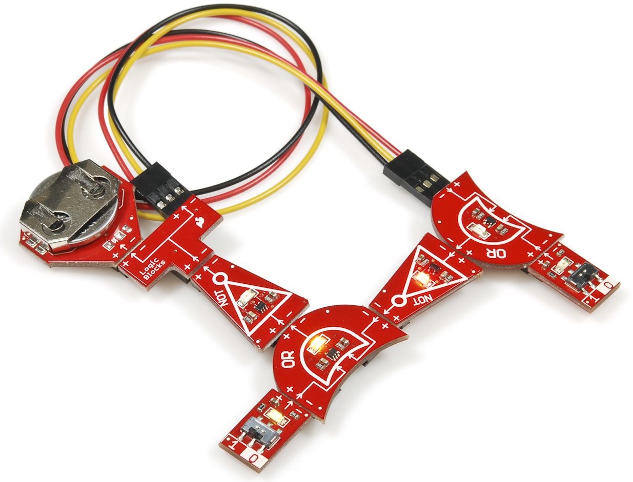
In our mind, we need to assign names to both inputs. One should be R (reset) the other should be S (set). Because the circuit is symmetric, it doesn't matter which input we call which, but the name of the input will affect which output is which.
There are two outputs to keep an eye on in this circuit; both are indicated by the red LEDs on the NOT gates. The NOT gate coming out of the OR gate with S as its direct input indicates the Q output. Our Q output is indicated by the red LED on the NOT gate fed by the OR gate with R as its input.
The Experiment
Give this series of steps a try, and observe both Q and Q outputs.
- We need an initial state to start us off. Begin by setting both S=0 and R=0.
- Now, set R=1. Q should "reset", if it wasn't already 0, it will become 0. If Q already was 0, it will stay there. Obeying our rule, Q should be 1.
- Set R=0. Nothing should change on Q or Q. They hold steady.
- Set S=1. Now Q should 'set' and go high, while Q goes low.
- Set S=0. There shouldn't be any effect on Q or its complement.
- Can you see how this might work as a piece of memory? Imagine a single bit of data being stored in the Q output!
- Try entering the restricted state by setting both S and R to 1. Q and Q should both be 0; our complement rule has been broken! To avoid this from happening safeguards will usually be placed on the inputs (in the form of more logic gates!), which will convert the restricted combination to an allowed input value.
Sub-Experiments
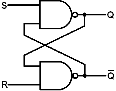
You can also make a latch out of NAND gates. Just swap the ORs with ANDs. Too keep the names of the inputs in line with the outcome they produce, we also swap the S and R inputs (or Q and Q, depending on how you look at it).
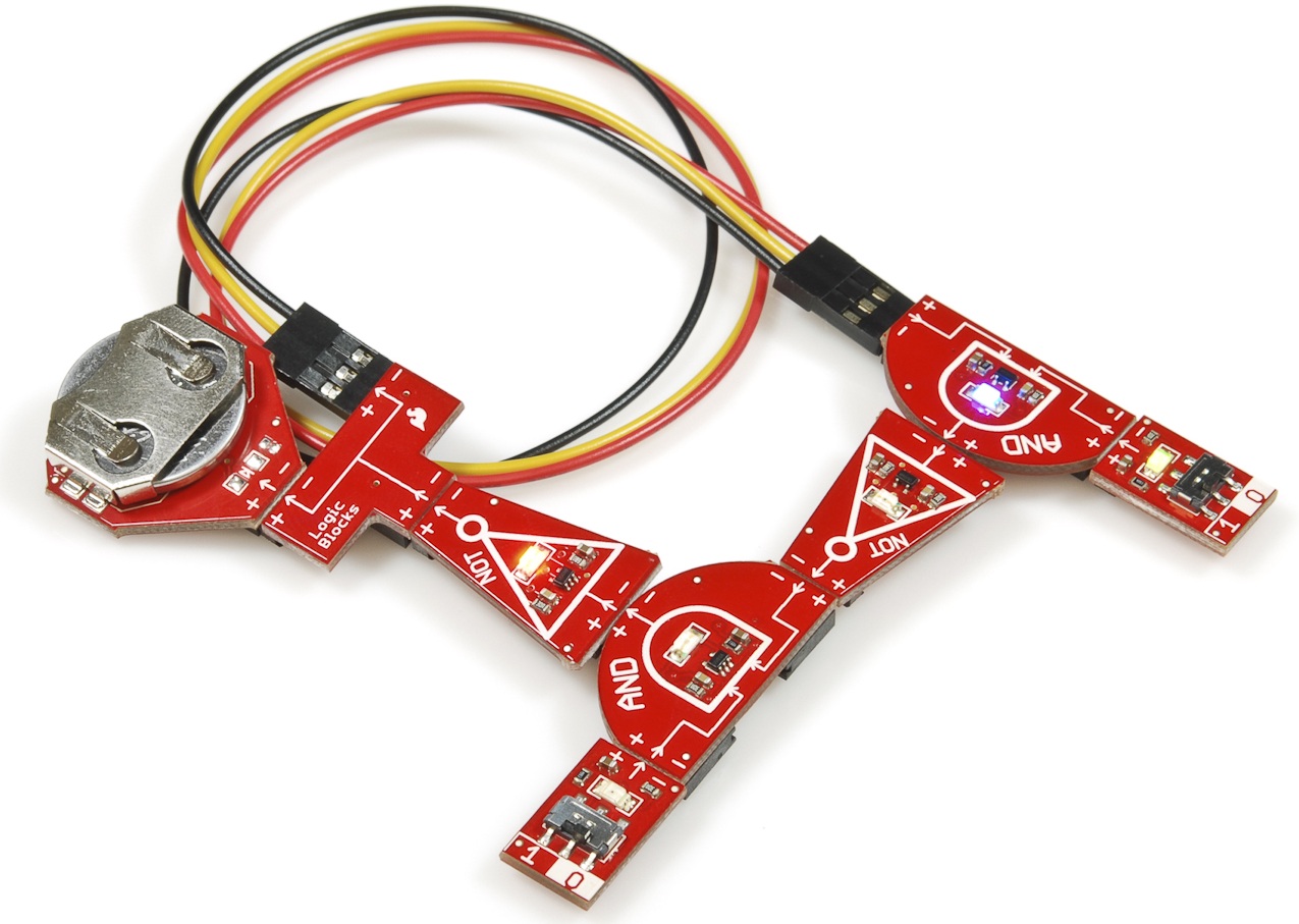
And lay it out with Logic Blocks like this (just replace the OR blocks with AND blocks):
You still have two stable states, but the truth table changes. Write out the state table for the NAND SR latch, and compare it with the NOR SR latch above. Which combination of inputs creates a restricted output in this case?
| S | R | Previous Q | Current Q | Current Q |
|---|---|---|---|---|
| 0 | 0 | 0 | ||
| 0 | 0 | 1 | ||
| 0 | 1 | 0 | ||
| 0 | 1 | 1 | ||
| 1 | 0 | 0 | ||
| 1 | 0 | 1 | ||
| 1 | 1 | 0 | ||
| 1 | 1 | 1 |
- Latches are the building blocks of many types of memory, including SRAM (static random access memory). As we've seen, a single latch can store one bit of data. How many latches do you think a piece of 1 Mb (1 million bits) SRAM has? How many NOR gates is that? Zounds!