LogicBlocks Experiment Guide
 jimblom
1. 2-Input AND Gate
The first experiment starts off as simple as possible: a dual-input, single output AND gate.
What You'll Need
- 1x AND Block
- 2x Input Blocks
- 1x Power Block
Circuit Diagram
LogicBlock Layout
Nothing too fancy here. An Input Block should be inserted into each of the AND Block's inputs. Then plug the Power Block into the output of the AND Block.

The blue LED on the AND Block will indicate the output status of the circuit.
The Experiment
Try all four possible input combinations: 0/0, 0/1, 1/0, and 1/1. Remember, this is what the AND gate's truth table should look like:
| Input A | Input B | Output |
|---|---|---|
| 0 | 0 | 0 |
| 0 | 1 | 0 |
| 1 | 0 | 0 |
| 1 | 1 | 1 |
- Does the blue AND block LED light up as you'd expect?
Sub-Experiments
While we're here, let's discuss the other two fundamental gates. A two-input OR and a single-input NOT.
Two-Input OR Gate
Can you lay out the fundamental, two-input OR gate with LogicBlocks? It'll require a similar set of blocks to the AND:
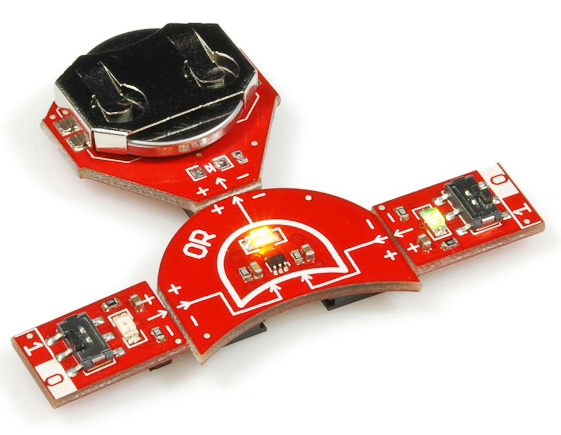
After experimenting with that, can you complete this truth table for the OR?:
| Input A | Input B | Output |
|---|---|---|
| 0 | 0 | |
| 0 | 1 | |
| 1 | 0 | |
| 1 | 1 |
Two-Input NOT Gate
Now do the same thing with the NOT gate.
This time you'll only need one Input Block:

Can you complete the NOT truth table?
| Input A | Output |
|---|---|
| 0 | 1 |
| 1 | 0 |
Now that you've got a handle of the three, fundamental logic gates, let's add some inputs! Onto the next experiment...