LogicBlocks Experiment Guide
 jimblom
4. Combinational Logic
The circuits in the previous experiments have all been examples of combinational logic circuits. In combinational circuits the output depends exclusively on the current state of the inputs. The circuit flows in one direction, from the inputs (traditionally) on the left, to the outputs on the right.
The opposite of combinational logic is sequential, in which a circuit's current output will affect its future outputs. But we'll get to that in later experiments.
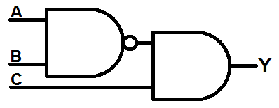
Here's an example of a combinational logic circuit we can build with LogicBlocks:
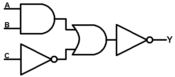
Given the input names shown in the circuit diagram (A and B feeding into the AND gate, C goes through the first NOT gate), we can form a boolean equation like this:
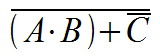
The output is the negation of ((A and B) or not C) (not the order of operations!). Let's build the above circuit with LogicBlocks!
What You'll Need
- 1x AND Block
- 1x OR Block
- 2x NOT Blocks
- 3x Input Blocks
- 1x Power Block
LogicBlock Layout
The output of an AND Block with two Input Blocks should be connected to one input of an OR Block. The other input of the OR Block should be connected to a NOT Block, which has an Input Block feeding into it. Finally, the output of the OR Block should feed into another NOT block, which is connected to a Power Block.

The output of this combinational logic circuit is represented by the red LED on the final NOT Block.
The Experiment
Try all eight possible input combinations and fill out this circuit's truth table:
| Input A | Input B | Input C | Output Y |
|---|---|---|---|
| 0 | 0 | 0 | |
| 0 | 0 | 1 | |
| 0 | 1 | 0 | |
| 0 | 1 | 1 | |
| 1 | 0 | 0 | |
| 1 | 0 | 1 | |
| 1 | 1 | 0 | |
| 1 | 1 | 1 |
- Does that jive with the equation from above?
- Have another look at that equation, or even the schematic. Recognizing the NANDs and NORs, could the equation be simplified by using De Morgan's Laws? Yes! First, push that inverter into the OR gate to turn it into a NOR:
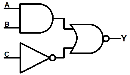
Then apply De Morgan's law: push the bubble through the NOR gate - turning that gate into an AND - and through to create NOT gates on both inputs:
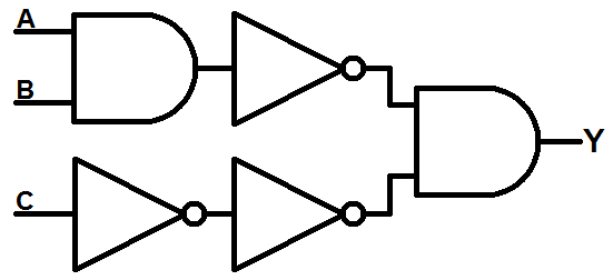
The two NOT gates on the C input would cancel each other out, so just get rid of them both. The NOT gate on the first AND's output can be pushed onto the gate to create a NAND gate:
We've completely eliminated the OR gate! Would you believe that this circuit produces the same truth table as the circuit at the beginning of this experiment? Try it out for yourself:

Sub-Experiments
- The next experiment takes a pretty giant leap from combinational to sequential logic. At this point, we'd really encourage you to just play around with the LogicBlocks, create your own circuits. Then try to draw out a circuit diagram, and a truth table.
- Are there any real-life scenarios you could imagine solving with digital logic?