Hazardous Gas Monitor
 jenfoxbot
 Build It
Below is the Fritzing diagram for the Hazardous Gas Monitor circuit. Since we are using the Photon Battery Shield breakout, make sure to connect the wires to the shield's pinouts instead of directly to the Particle Photon's header pins shown in the image. Additionally, the LiPo battery will be connected to the Photon battery Shield's JST connector underneath the Particle Photon.
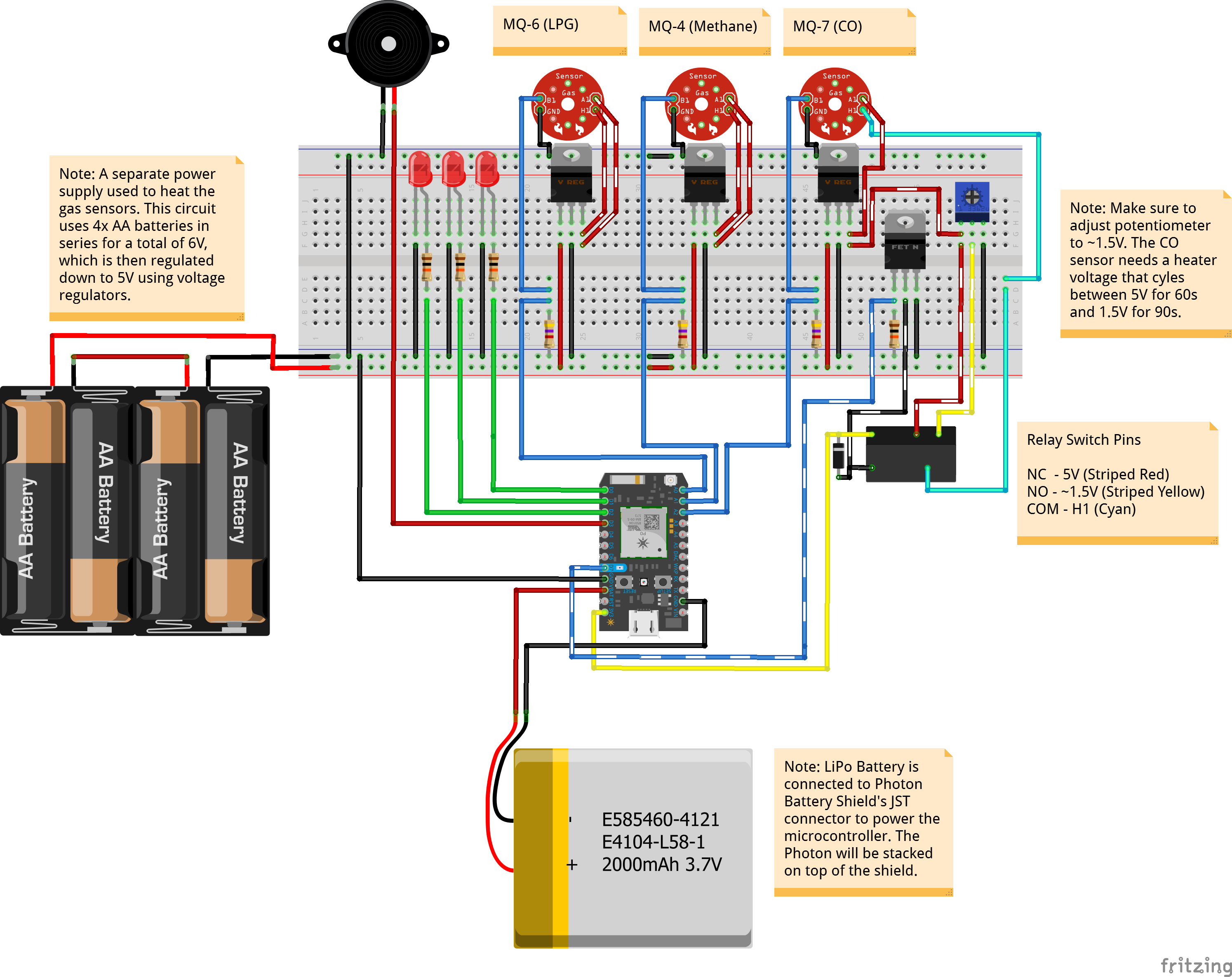
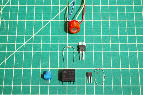
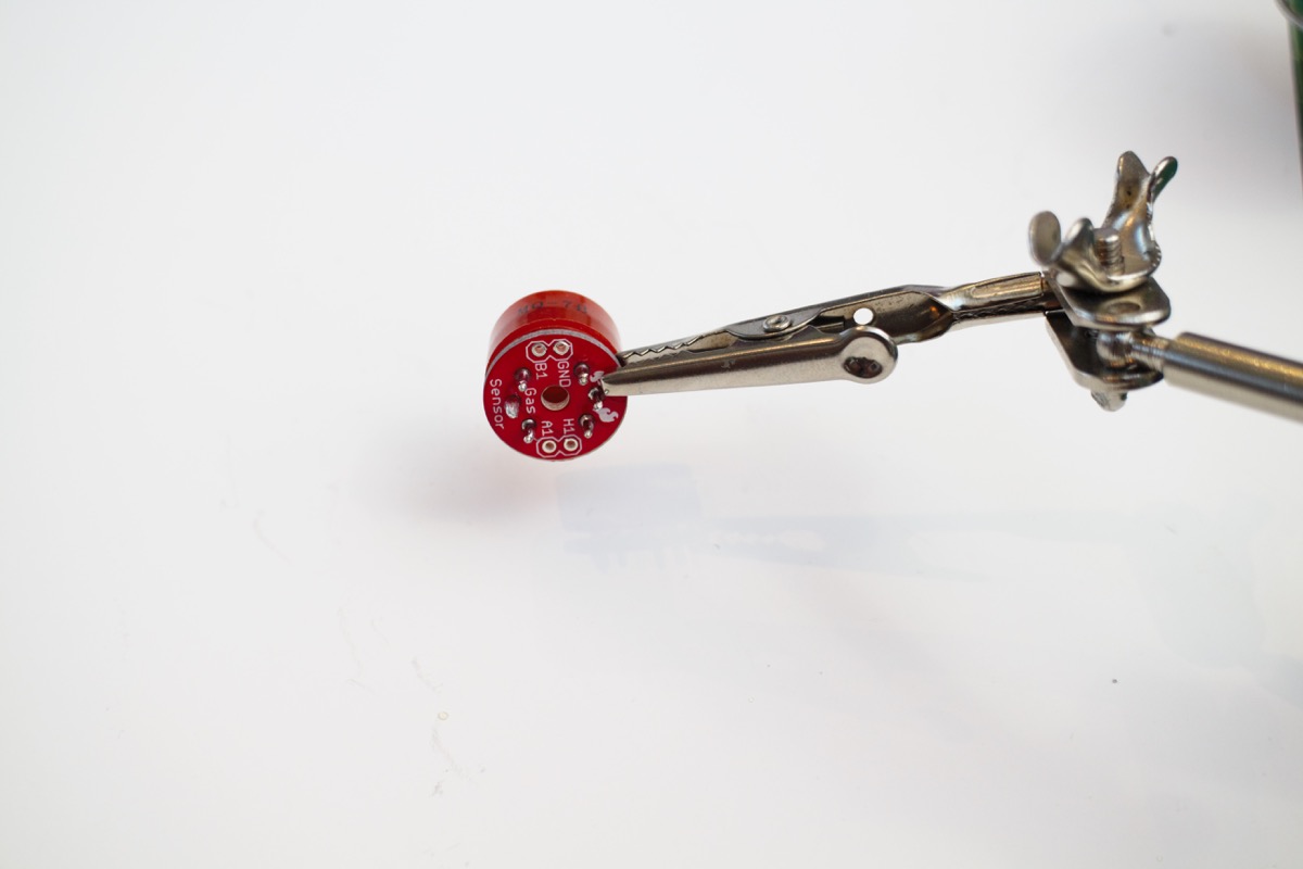
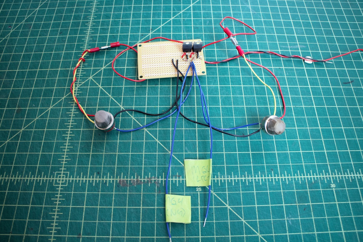
Solder gas sensor breakout boards to gas sensors. Orientation doesn't matter, just be sure that the silkscreen (aka labels) are facing down so that you can read them (had to learn that one the hard way..). Solder wires to the gas sensor breakout board.

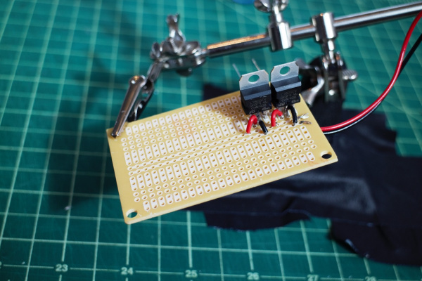
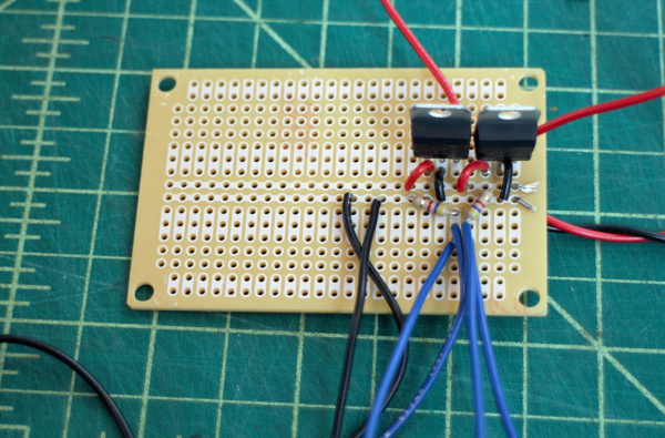
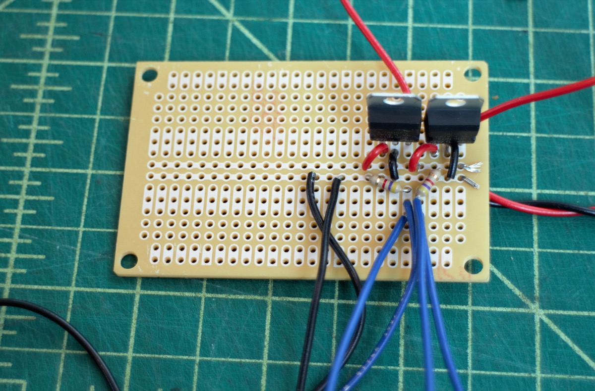
Solder three voltage regulators to the PCB board. For each regulator, connect positive battery output to the regulator input, and connect middle voltage regulator pin to ground.
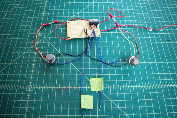
Connect the LPG (MQ6) and Methane (MQ4) sensors.
For each sensor:
- Connect H1 and A1 to the output of one of the voltage regulators (recommended to use an electrical connector).
- Connect GND to ground.
- Connect B1 to Photon analog pin (LPG goes to A0, Methane to A1)
- Connect a 4.7 kΩ resistor from B1 to ground.
Connect the CO (MQ7) gas sensor.
Aside: The MQ7 sensor requires cycling the heater voltage (H1) between 1.5V (for 90s) and 5V (for 60s). One way to do this is to use a relay triggered by the Photon (with the aid of a MOSFET and potentiometer) -- when the relay is not powered, the voltage across H1 is 5V, and when the relay is powered the voltage across H1 is ~ 1.5V.
- Connect GND to ground.
- Connect B1 to Photon analog pin (A2). Connect 4.7 kΩ resistor from B1 to ground.
- Connect A1 to third voltage regulator output (5V source).
- Connect Photon 3.3V pin to positive relay input.
- Connect Photon Digital Pin D7 to left MOSFET pin, and a 10 kΩ resistor to ground.
- Connect middle MOSFET pin to relay ground pin. Connect right MOSFET pin to ground.
- Connect relay Normally Open ("NO") pin to A1, and the Normally Closed ("NC") pin to middle potentiometer pin.
- Connect right potentiometer pin to ground, and left pin to A1.
- Connect relay Common ("COM") pin to H1.
- Adjust potentiometer resistance until it changes the relay output to ~ 1.5V when the relay receives power.
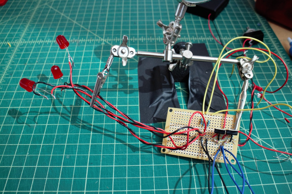
Connect an LED and 10 kΩ resistor to each of the Photon digital pins D0, D1, and D2. Connect buzzer to Photon digital pin D4.
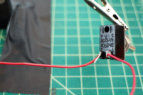
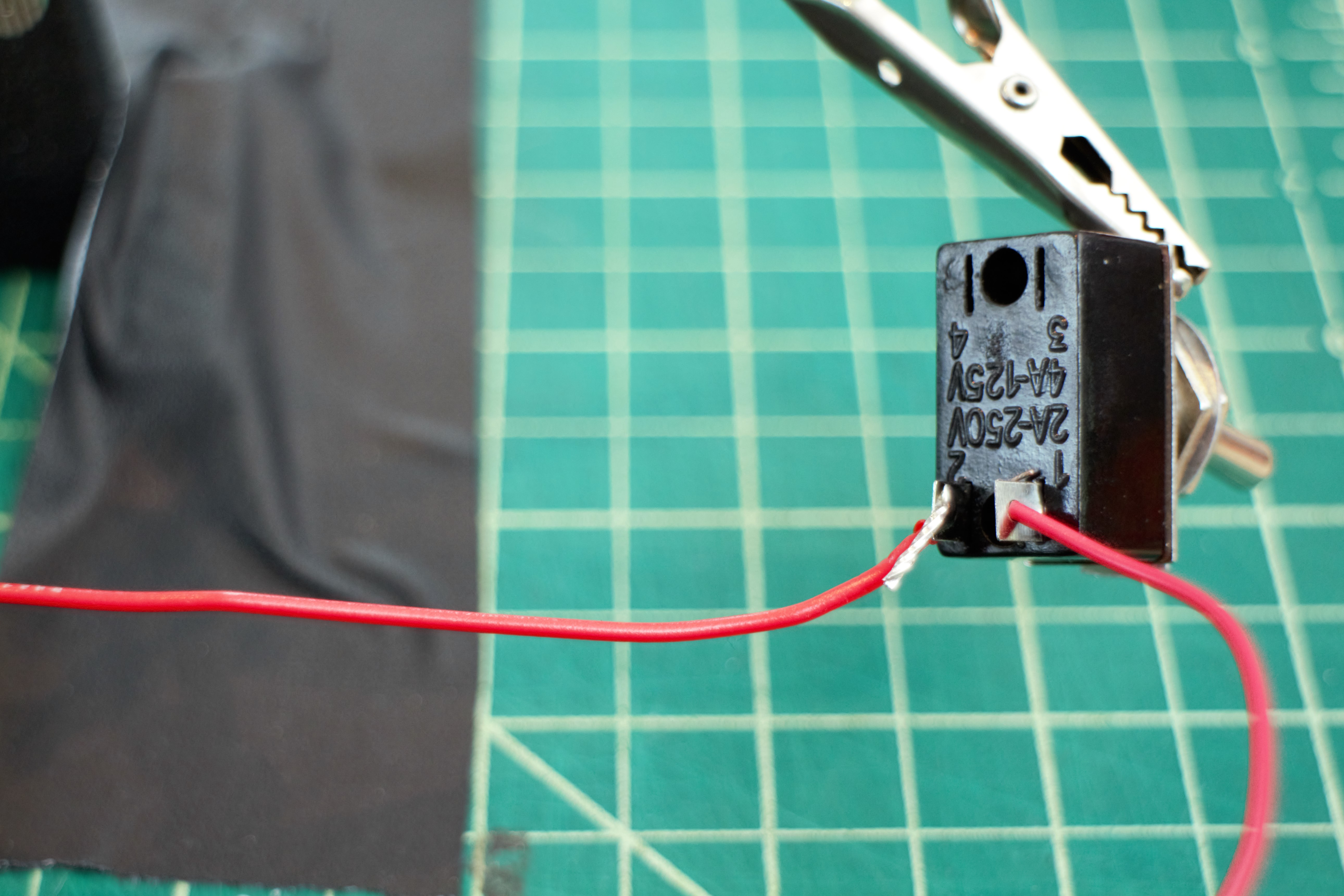
Connect toggle switch between battery pack and PCB board power. Recommended to include an electrical connector for the battery pack to make it easier to switch out batteries.
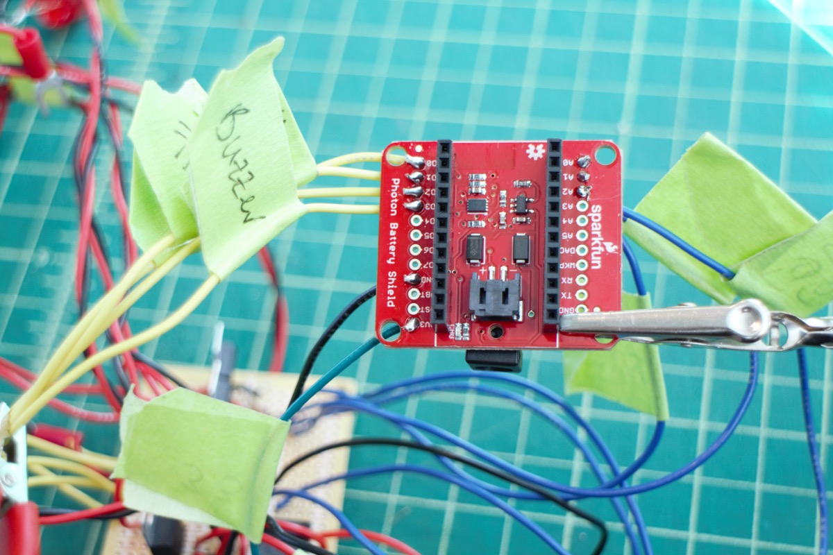
Solder wires to Photon Battery Shield breakout.
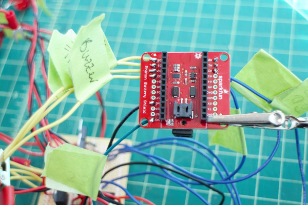
Connect lamp switch between LIB and Photon battery shield -- recommended to use an extra JST cable for this to keep the LIB battery cable in tact (and make it easier to install the lamp switch).
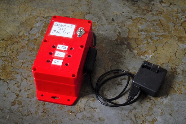
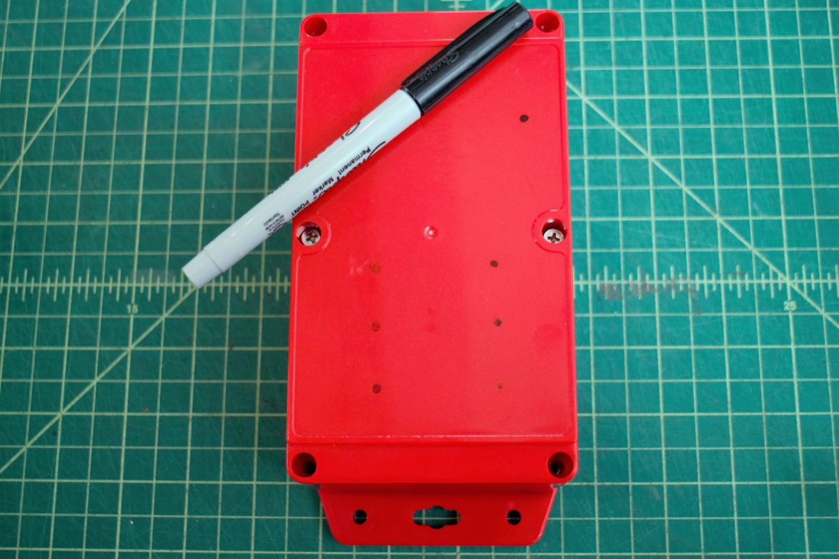
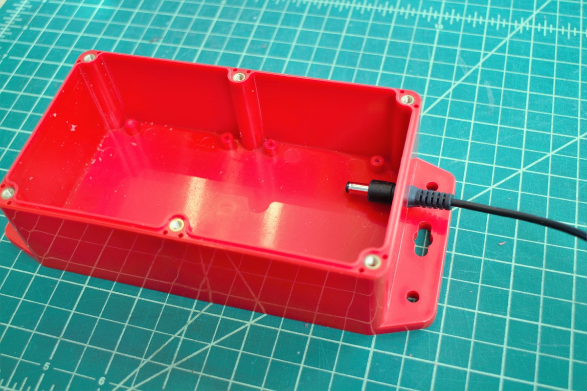
Build a case for the electronics!

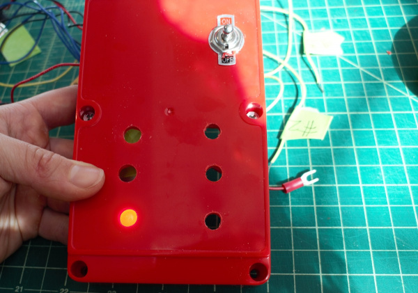
- Drill hole for toggle switch on case lid.
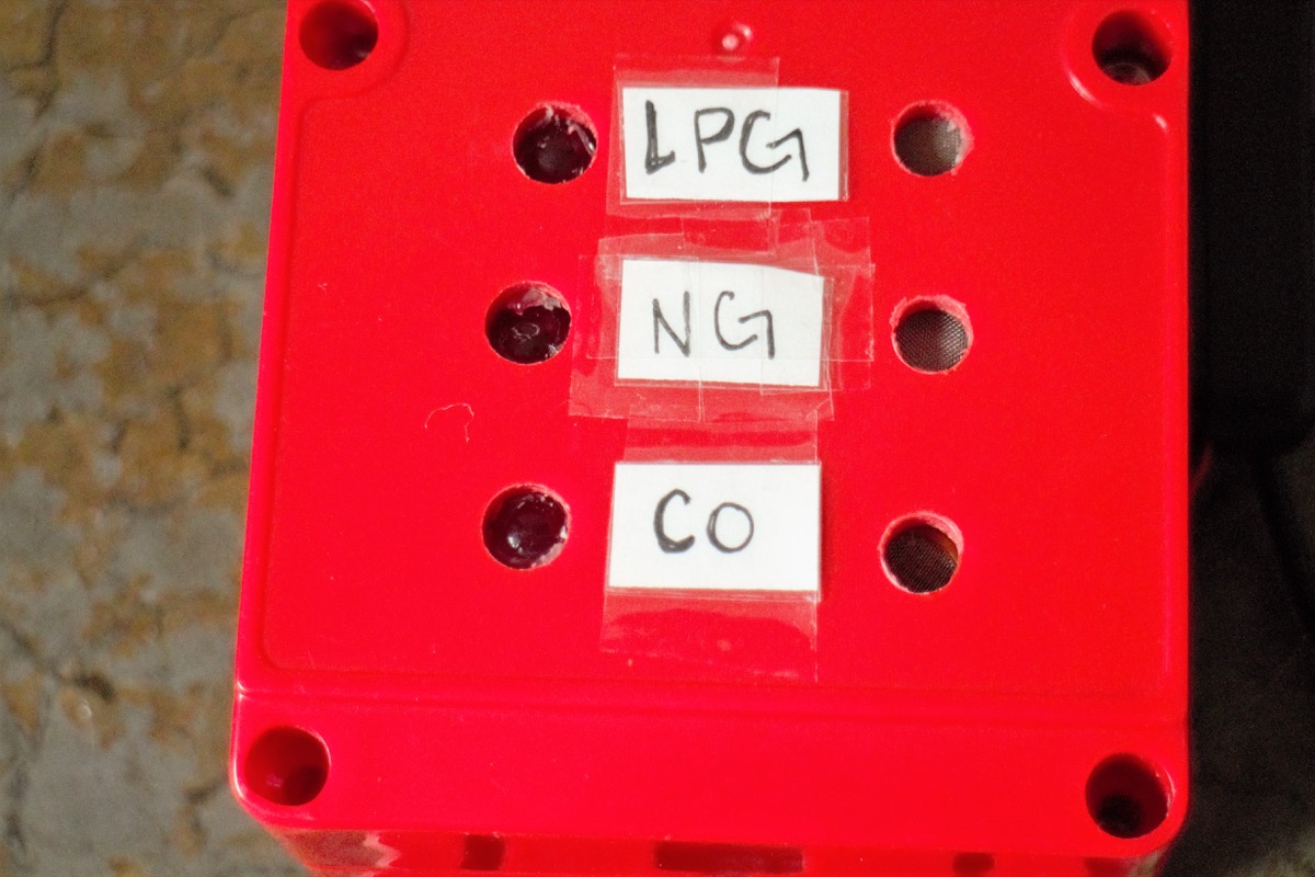
Drill 3 holes in the case lid for the LED lights to shine through, and 3 holes for the gas sensors to have air contact. Adhere components on the inside of the lid.
Drill hole in the side of the case for barrel jack USB cord to connect to the Photon Battery Shield.

Drill two small holes on the side of the case for the lamp switch cable. Adhere lamp switch to side of case.
- Label the LEDs with its corresponding gas sensor on the outside of the case.

Check electrical connections and, if everything is good to go, coat electrical connections in epoxy or hot glue.


