H3LIS331DL Accelerometer Breakout Hookup Guide
 SFUptownMaker
 Introduction
The H3LIS331DL is a high-g accelerometer with I2C and SPI interface options. It offers an adjustable output range of 100, 200, or 400g, and an adjustable data rate of up to 1kHz.
Required Materials
Please check the wish list below for items required to follow this tutorial.
Tools
No special tools are required to follow this tutorial. You will need a soldering iron, solder, and general soldering accessories.


Suggested Reading
We suggest reviewing the tutorials below to ensure that you're up-to-date with all of the skills necessary to follow this hookup guide.
How to Solder: Through-Hole Soldering
Installing an Arduino Library
Serial Peripheral Interface (SPI)
Logic Levels
I2C
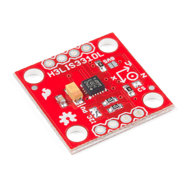
Hardware Overview
The H3LIS331DL breakout is fairly simple.
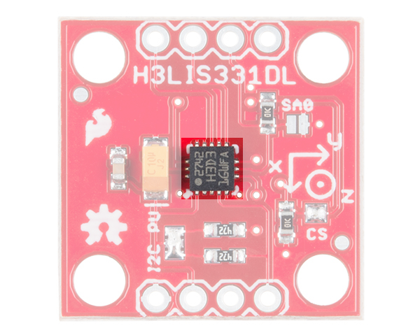
H3LIS331DL Sensor IC - This is the sensor IC. Its operating voltage only extends up to 3.6V, so to use it with a 5V Arduino or Arduino clone, you'll need some kind of voltage translation! It is perfectly centered on the PCB.
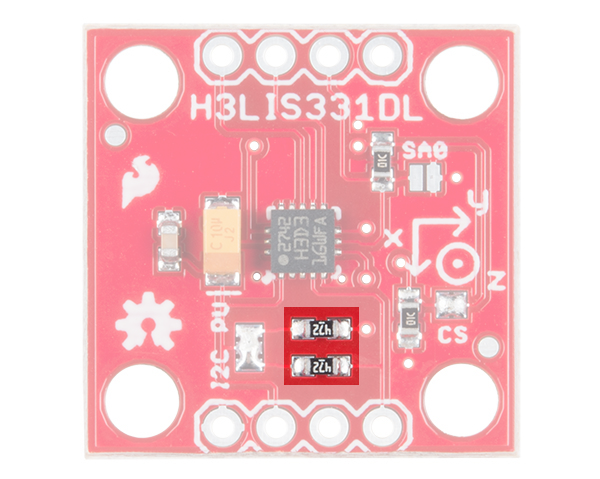
I2C Pull-up Resistors - The board includes pull-up resistor so you don't need to add them externally.
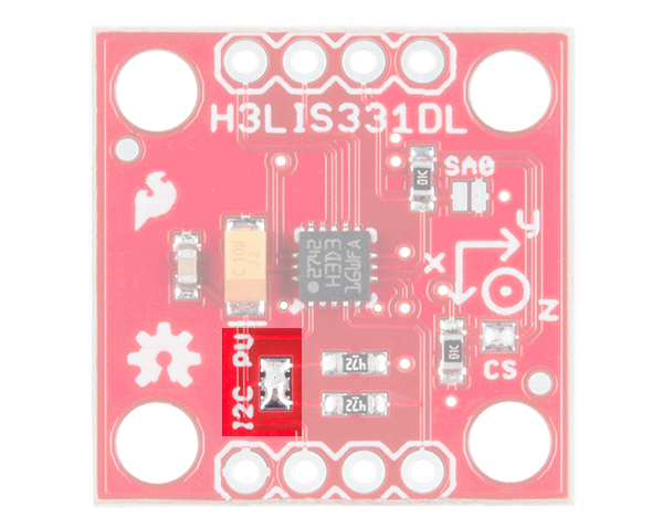
I2C Pull-up Resistor Isolation Jumper - If necessary, the I2C pull-up resistors can be removed from the circuit by removing the solder from this jumper.
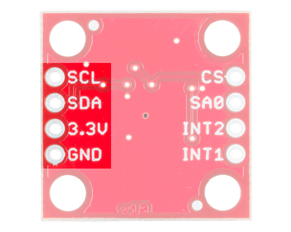
SparkFun Standard I2C Header - Most boards which can be communicated to via I2C use this pinout, making it easy to stack them or connect them in a daisy chain.
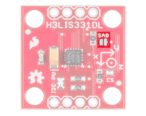
SA0 Jumper - Closing this jumper changes the I2C address of the sensor from 0x19 to 0x18.
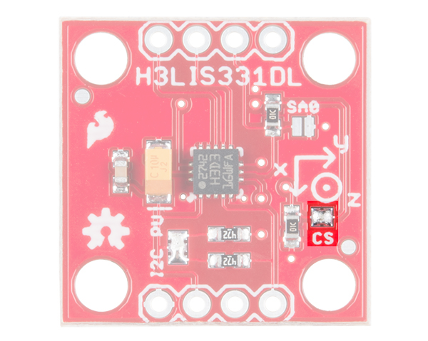
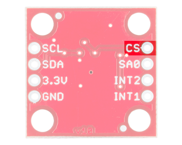
CS Jumper - Removing the solder from this jumper enables SPI mode. When the part's CS line is low at boot, it enables SPI mode.
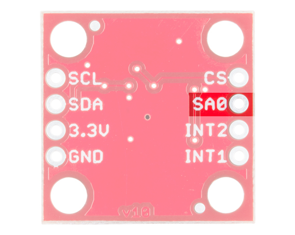
SA0 Pin - When the chip is in SPI mode, this goes from being the address select pin to being the MISO pin.
CS Pin - Chip select for SPI mode. Unused in I2C mode.
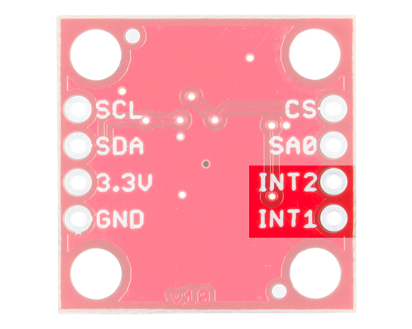
Interrupt Pins - These pins are tied to interrupts that can be setup by the software library to trigger on various conditions.
Library Overview
Here's a list of the functions supported by the Arduino library for the LIS331 family.
begin(comm_mode mode) - Sets the communications mode to be used by the library (LIS331::USE_I2C or LIS331::USE_SPI), sets the power mode to normal, enables the axes, sets the sampling rate to 50Hz, and resets all the other registers to 0.
setI2CAddr(address) - Sets the I2C address. By default this is
going to be 0x19. If the SA0 jumper is soldered closed, it is 0x18. This
function must be called before begin() so the library knows what address to
use for communications.
setSPICSPin(pin) - Sets the SPI mode chip select pin. This function must be
called before begin() so the library knows which pin to use for
communications.
axesEnable(bool enable) - Pass true to enable the axes or false to disable
them.
setPowerMode(power_mode pmode) - Sets the power mode of the chip. This
affects the data rate as well. Options are:
LIS331::POWER_DOWN- Minimizes chip power usage but no data or communications are possibleLIS331::NORMAL- Normal power mode. Data rate is set by thesetODR()function.LIS331::LOW_POWER_0_5HZ- Low power mode, 0.5Hz data rate.LIS331::LOW_POWER_1HZ- Low power mode, 1Hz data rate.LIS331::LOW_POWER_2HZ- Low power mode, 2Hz data rate.LIS331::LOW_POWER_5HZ- Low power mode, 5Hz data rate.LIS331::LOW_POWER_10HZ- Low power mode, 10Hz data rate.
setODR(data_rate drate) - Sets the data rate for the part, when in normal
power mode only. Options are:
LIS331::DR_50HZ- Set the data rate to 50Hz.LIS331::DR_100HZ- Set the data rate to 100Hz.LIS331::DR_400HZ- Set the data rate to 400Hz.LIS331::DR_1000HZ- Set the data rate to 1000Hz.
readAxes(int16_t &x, int16_t &y, int16_t &z) - Pass three int16_t variables
to this function and those variables will be populated with the appropriate
value from the accelerometer.
convertToG(maxScale, reading) - Converts from raw data to an actual
g-reading. The first parameter is the maximum reading for the current mode, as
set by the setFullScale() function. Options are 6/12/24g for the LIS331HH and
100/200/400g for the H3LIS331DL.
setHighPassCoeff(high_pass_cutoff_freq_cfg hpcoeff) - Set the coefficient for
the high pass filter. The actual cutoff frequency is dependent upon the data
rate set by setODR(). The cutoff frequency is (fs)/(6*Hpc), where fs is the
sampling frequency and Hpc is the high pass coefficient as set by these
constants:
LIS331::HPC_8- Sets coefficient to 8.LIS331::HPC_16- Sets coefficient to 16.LIS331::HPC_32- Sets coefficient to 32.LIS331::HPC_64- Sets coefficient to 64.
enableHPF(bool enable) - true to enable, false to disable.
HPFOOnIntPin(bool enable, intSource) - Does the high pass filter apply to the
signal the interrupt is based on? true to enable, false to disable, and the
second parameter is 1 or 2 depending on which interrupt you wish to apply this
setting to.
intActiveHigh(bool enable) - Pass true to set the interrupt pin to active
high, false to set it as active low. Default value is active high.
intPinMode(pp_od _pinMode) - Are the interrupt pins open-drain or push pull?
Pass LIS331::PUSH_PULL or LIS331::OPEN_DRAIN.
intSrcConfig(int_sig_src src, pin) - What sort of thing triggers an
interrupt, and which pin shows the interrupt. The options are:
LIS331::INT_SRC- Interrupt source is the same as the pin number.LIS331::INT1_2_SRC- Either interrupt will be reflected on the pin.LIS331::DRDY- The "new data ready" signal will be reflected on the pin.LIS331::BOOT- The boot mode status of the part is reflected on the pin.
setFullScale(fs_range range) - Sets the range of the part, as listed below:
LOW_RANGE- +/-6g for the LIS331HH or +/-100g for the H3LIS331DH.MED_RANGE- +/-12g for the LIS331HH or +/-200g for the H3LIS331DH.HIGH_RANGE- +/-24g for the LIS331HH or +/-400g for the H3LIS331DH.
bool newXData() - returns true if new X data is available since last read
of X data register.
bool newYData() - same as newXData() for Y axis.
bool newZData() - same as newZData() for Z axis.
enableInterrupt(int_axis axis, trig_on_level trigLevel, interrupt, bool
enable)
- axis can be LIS331::X_AXIS, LIS331::Y_AXIS, or
LIS331::Z_AXIS. trigLevel can be LIS331::TRIG_ON_HIGH or
LIS331::TRIG_ON_LOW, interrupt can be 1 or 2, and enable is true to
enable the interrupt and false to disable it.
setIntDuration(duration, intSource) - duration can be any value from 0-127,
and represents the time in number of samples that the sensor must read above or
below the threshold set by the user. intSource is 1 or 2.
setIntThreshold(threshold, intSource) - threshold is the absolute magnitude
above or below which an interrupt will occur, divided by 16. It can range from
0-127. intSource is 1 or 2.
Examples
Hardware Hookup
The H3LIS331DL supports I2C, SPI, and three-wire SPI data transfer. The library supports I2C and SPI mode. Obviously, since SPI requires four wires and I2C only requires two, there are different circuit configurations for each mode. Now would be a good time to solder the female headers to the Arduino Pro 3.3V/8MHz and breakaway headers to the H3LIS331DL sensor before connecting the boards together.
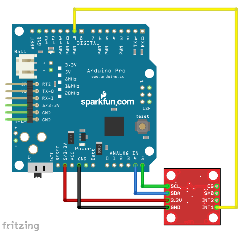
I2C Mode
The board is labeled for I2C mode. Here you can see it connected to a 3.3V Arduino Pro. Note that connecting the board to a 5V Arduino can damage it.
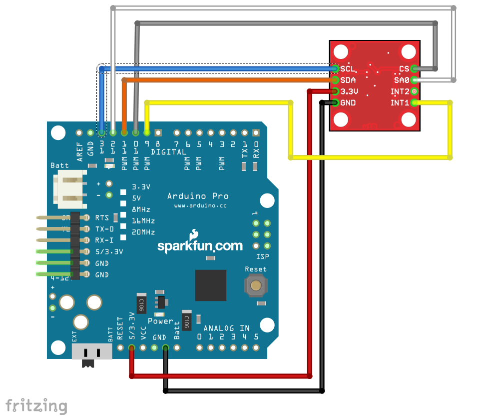
SPI Mode
In SPI mode, the SDA pin becomes MOSI, the SCL pin becomes clock, the address select pin SA0 become MISO, and the CS pin is used for chip select.
Example Code
Note: This example assumes you are using the latest version of the Arduino IDE on your desktop. If this is your first time using Arduino, please review our tutorial on installing the Arduino IDE. If you have not previously installed an Arduino library, please check out our installation guide.
You will also need FTDI drivers installed in order to upload code to the Arduino Pro. If this is your first time using an FTDI, make sure to follow our tutorial: USB Serial Driver Quick Install.
To follow along with the examples, the code requires the LIS331 Arduino library. Make sure that the library has been installed.
For the most part, the example code for SPI mode and I2C mode is identical. The only part that differs is the intial setup where you configure the pins to be used and the library's settings.
I2C Mode Setup
Here's an example of the same section of code from an I2C configured
system. It's important to note that order matters here: Wire.begin() and xl.setI2CAddr() must be
called before xl.begin().
language:c
#include "SparkFun_LIS331.h"
#include <Wire.h>

LIS331 xl;

void setup()
{
  // put your setup code here, to run once:
  pinMode(9,INPUT);       // Interrupt pin input
  Wire.begin();
  xl.setI2CAddr(0x19);    // This MUST be called BEFORE .begin() so
                          //  .begin() can communicate with the chip
  xl.begin(LIS331::USE_I2C); // Selects the bus to be used and sets
                          //  the power up bit on the accelerometer.
                          //  Also zeroes out all accelerometer
                          //  registers that are user writable.
SPI Mode Setup
Here we have the first few lines of an SPI mode sketch. Again, order is important: pinMode(), SPI.begin(), and
xl.setSPICSPin() functions must all be called before the xl.begin()
function is called.
language:c
#include "SparkFun_LIS331.h"
#include <SPI.h>

LIS331 xl;

void setup()
{
  // put your setup code here, to run once:
  pinMode(9,INPUT);       // Interrupt pin input
  pinMode(10, OUTPUT);    // CS for SPI
  digitalWrite(10, HIGH); // Make CS high
  pinMode(11, OUTPUT);    // MOSI for SPI
  pinMode(12, INPUT);     // MISO for SPI
  pinMode(13, OUTPUT);    // SCK for SPI
  SPI.begin();
  xl.setSPICSPin(10);     // This MUST be called BEFORE .begin() so
                          //  .begin() can communicate with the chip
  xl.begin(LIS331::USE_SPI); // Selects the bus to be used and sets
                          //  the power up bit on the accelerometer.
                          //  Also zeroes out all accelerometer
                          //  registers that are user writable.
After this point, the code for either mode of operation is the same. Note that this example code includes only the second half of the setup function, and if you're copy/pasting from this example, you must copy the other half of the setup function from one of the above code chunks.
language:c
  // This next section configures an interrupt. It will cause pin
  //  INT1 on the accelerometer to go high when the absolute value
  //  of the reading on the Z-axis exceeds a certain level for a
  //  certain number of samples.
  xl.intSrcConfig(LIS331::INT_SRC, 1); // Select the source of the
                          //  signal which appears on pin INT1. In
                          //  this case, we want the corresponding
                          //  interrupt's status to appear.
  xl.setIntDuration(50, 1); // Number of samples a value must meet
                          //  the interrupt condition before an
                          //  interrupt signal is issued. At the
                          //  default rate of 50Hz, this is one sec.
  xl.setIntThreshold(2, 1); // Threshold for an interrupt. This is
                          //  not actual counts, but rather, actual
                          //  counts divided by 16.
  xl.enableInterrupt(LIS331::Z_AXIS, LIS331::TRIG_ON_HIGH, 1, true);
                          // Enable the interrupt. Parameters indicate
                          //  which axis to sample, when to trigger
                          //  (in this case, when the absolute mag
                          //  of the signal exceeds the threshold),
                          //  which interrupt source we're configuring,
                          //  and whether to enable (true) or disable
                          //  (false) the interrupt.
  Serial.begin(115200);
}

void loop()
{
  static long loopTimer = 0;
  int16_t x, y, z;
  if (millis() - loopTimer > 1000)
  {
    loopTimer = millis();
    xl.readAxes(x, y, z);  // The readAxes() function transfers the
                           //  current axis readings into the three
                           //  parameter variables passed to it.
    Serial.println(x);
    Serial.println(y);
    Serial.println(z);
    Serial.println(xl.convertToG(100,x)); // The convertToG() function
    Serial.println(xl.convertToG(100,y)); // accepts as parameters the
    Serial.println(xl.convertToG(100,z)); // raw value and the current
    Serial.println(" ");                // maximum g-rating.
  }
  if (digitalRead(9) == HIGH)
  {
    Serial.println("Interrupt");
  }
}
After placing the code into the Arduino IDE, select the board definition and COM port to upload. Once compiled, check out the sensor readings by opening up a serial monitor set to 115200 baud.
Resources and Going Further
Now that you've successfully got your H3LIS331DL up and running, it's time to incorporate it into your own project!
- For lower dynamic ranges (6-24g) SparkFun offers the LIS331 breakout board, which is library compatible with this one.
For more information, check out the resources below:
- Schematic
- Eagle Files (ZIP)
- H3LIS331DL Datasheet (PDF)
- Product Showcase Video
- ShawnHymel's H3LIS331_Ball_Demo.ino - Code used for the Produce Showcase Demo.
- GitHub Repo
- Arduino Library Code Repo
Need some inspiration for your next project? Check out some of these related tutorials: