Getting Started with the Red Hat Co.Lab Robot
 D___Run___,
  Gina Likins
Build: Complete the Wiring
In this section, you will add brains of the robot: the micro:bit and SparkFun moto:bit and wire everything up for power.
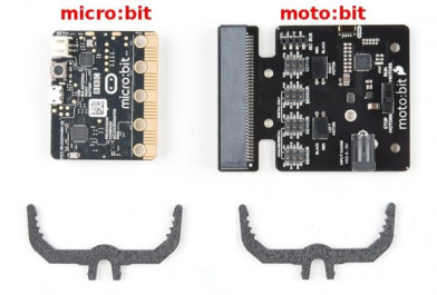
Find the micro:bit, the moto:bit, and the two moto:bit Mounting brackets.
Attach one of the moto:bit Mounts by snapping it into one of the vertical slots in the back of the top chassis near the large rectangular opening.
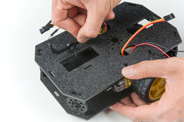
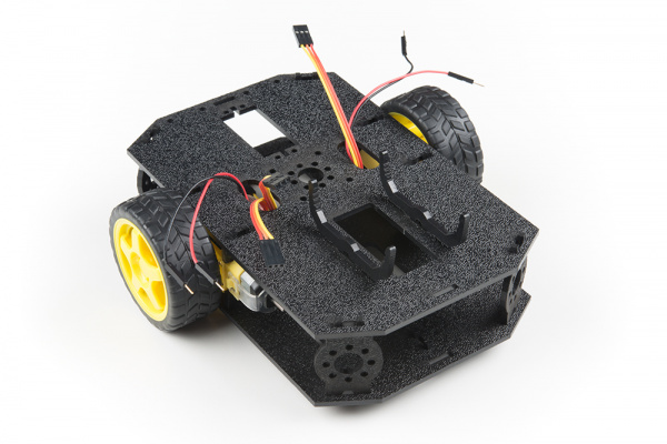
Attach the other moto:bit Mount by snapping it into the other slot:
Time to insert your micro:bit into the moto:bit.
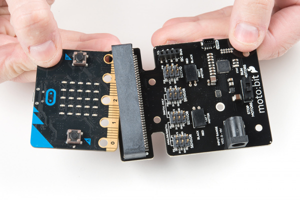
The moto:bit snaps into the second-lowest of the notches on the moto:bit Mounts. Make sure the power jack is facing the left side of the robot. Push gently and evenly until it snaps into place.
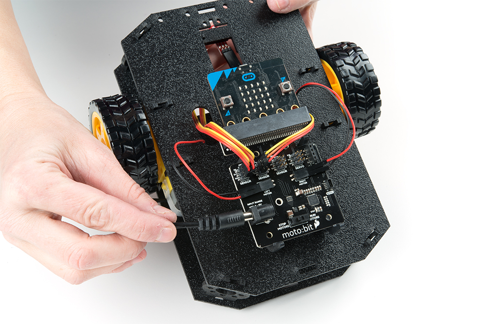
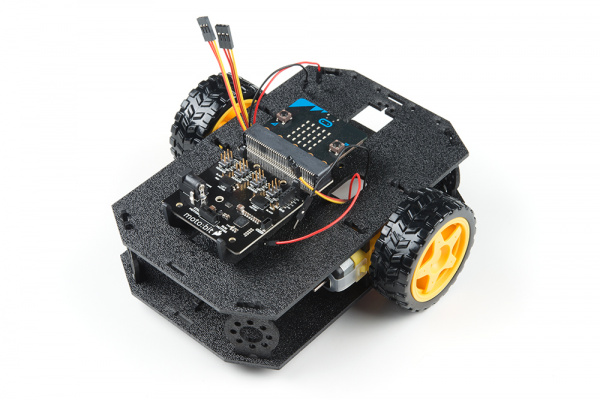
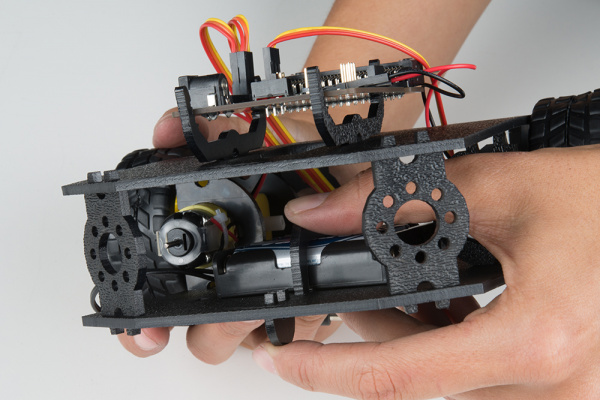
Here’s what everything looks like before connecting the wires:
To hook up the motors, put your robot in front of you with the Sensor Array pointing away from you (as if it were going to drive away from you). While you’re making your connections it’s especially helpful to be able to keep the robot oriented correctly, so if you haven’t done so already, you may want to mark the left front corner of the robot in some way.
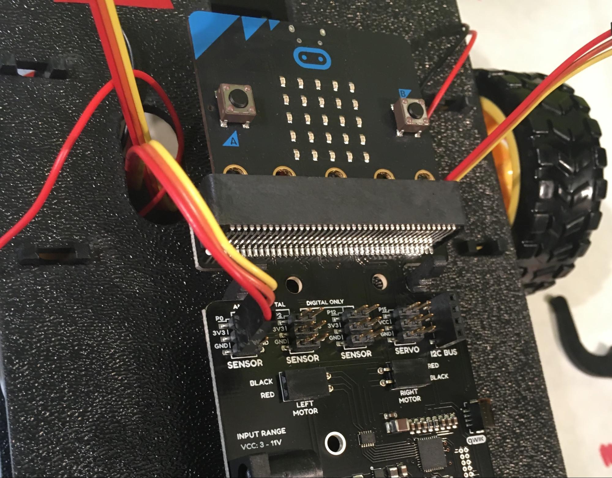
First, connect the Left Sensor cable bundle (which is the one coming out of the left oval that you didn't mark) to the moto:bit sensor pins labeled P0, 3V3, GND. Since RED was GND when we connected the cable bundle at the sensor end, RED needs to stay GND when we connect the cable bundle at the moto:bit end.
Once the cable bundle is plugged in the YELLOW wire should be closest to the front of the robot, and the RED wire should be closest to the rear of the robot, like this:
Then connect the Middle Line Sensor (the cable bundle that does have tape on it coming out of the left hole) with the pins P1, 3V3 and GND, again making sure that the RED wire stays connected to GND:

Connect the Right Line Sensor cable bundle (which comes out of the right hole) with the pins P2, 3V3, and GND
Next we’re connecting the motors, which is a little weird, but stick with me.
To make a long story short, there’s no way to determine which direction the shaft for each of your two motors will spin before getting it hooked up and running. So, what we’re going to do is hook them up the way the moto:bit board indicates for now. Once we have everything else assembled (and we’re close -- only the power is left to do after this), we’ll load some sample code and see if the motors do what we expect them to do.
If they do -- yah! If they don’t, that’s ok too -- we'll go through how to figure out which of the motor(s) is backwards and how to fix it.
Hook up the left red and black motor wires (which come out of the left hole on the Top Chassis) to the left motor connection on the moto:bit board, plugging the red wire into the hole labeled “red” and the black wire into “black”):

Connect the right red and black motor wires (coming out of the right hole) to the right motor connection on the moto:bit board in the same way:
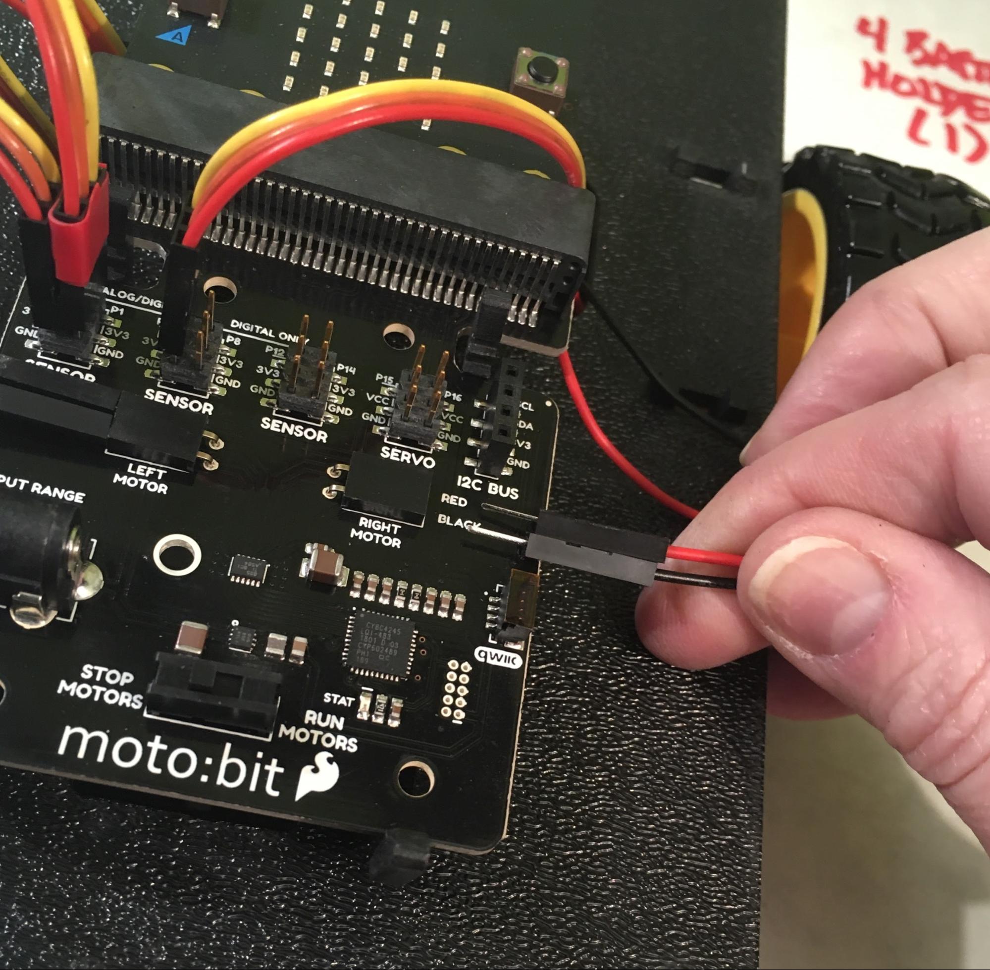
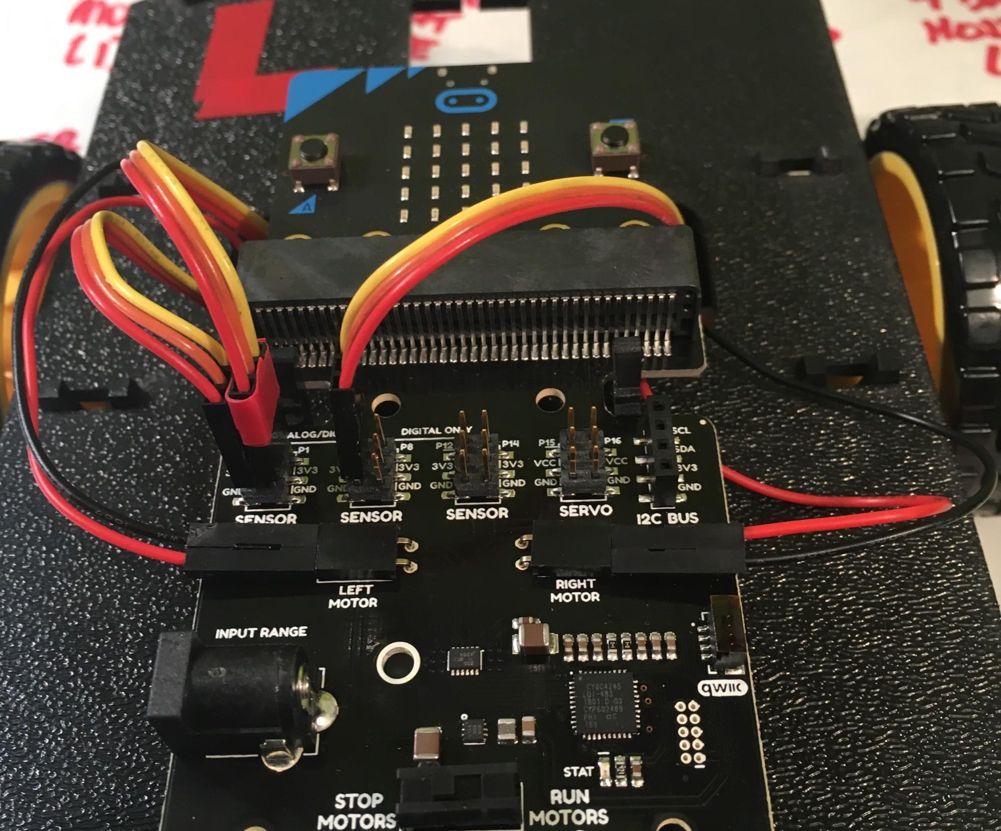
When you’re finished, you’ll have something that looks like this:
POWER!
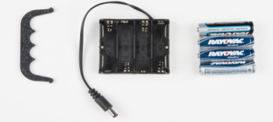
Now we need to give your robot some juice. The power -- supplied by 4 (four) AA batteries -- goes into the moto:bit, which then powers the micro:bot. You’ll need the Battery Pack Clip , the 4 AA Battery Holder, and the provided AA batteries:
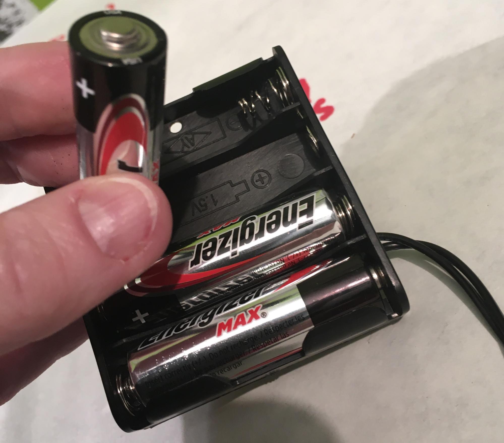
First insert the batteries into the Battery Holder, making sure that you face them in the correct direction, as shown in the diagram on the inside of the holder(the flat end of the battery, which is the negative end, goes against the spring end of the battery case):
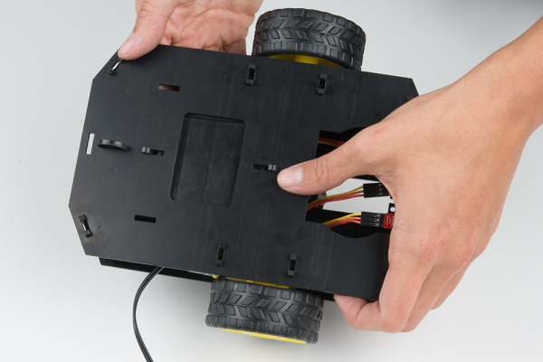
With your robot in front of you and pointing away from you, orient the Battery Holder (with batteries) as shown, then insert it into the back cavity of the chassis:
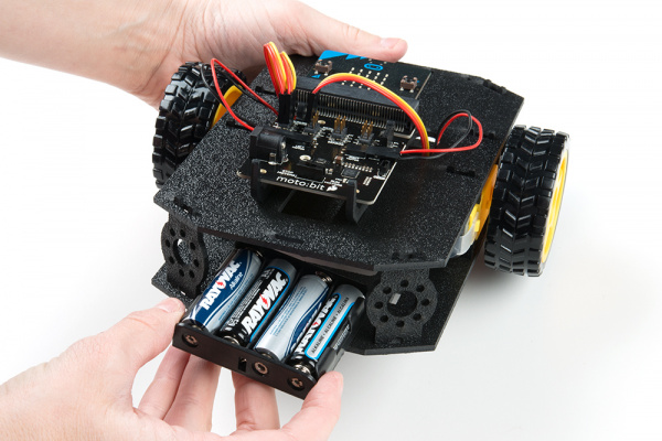
left side of the robot and the Battery holder sits on top of the hole. Insert the Battery Pack Clip on top of the battery pack (with the open end facing down towards the batteries), twist and position the clip so that it rests on top of the battery pack.
It worked best for me if I reached in through the hole nearest the sensor to hold the battery pack in place with one hand while I used the other to wiggle the Battery Pack clip into place.
Push the clip down into the vertical slots in the Bottom Chassis so it snaps in place.
Route the barrel jack cable out of the left side of the chassis and up to the moto:bit and plug the barrel jack cable into the barrel connector on the side of the moto:bit carrier board.