Getting Started with the Red Hat Co.Lab Robot
 D___Run___,
  Gina Likins
Introduction
The Red Hat Co.Lab Robot Kit has everything you need to build a robot that can do all sorts of cool things: follow a line on the floor, scroll a message in lights, run a maze, and much more. The brain of the robot is the micro:bit, a microcontroller that’s packed with functionality, including: a 25 LED matrix screen, two buttons for controlling the action, a compass, an accelerometer, a temperature sensor, and Bluetooth.

In addition, there are three infrared light sensors, which allow your robot to “see”, and an open hardware controller, the moto:bit, that works with the micro:bit to control the motors and receive information from the sensors.
Because the entire micro:bit environment is open source -- and everything SparkFun and Red Hat creates is open source -- SparkFun was able to create software “blocks” for the micro:bit, which you’ll use in your program.
In this activity, you assemble your Red Hat Co.Lab Robot Kit, connect the micro:bit, download sample code, and run your robot for the first time.
After getting your ‘bot running, you can learn how one open source software project has become a global phenomenon in robotics by watching Red Hat’s Open Source Stories film “How to start a robot revolution"
Before You Start
Before starting any project, there are some steps to take to ensure that you don't hit any problems and that things go smoothly. Here's our recommendations to ensure a successful robot build.
Recommended Age and Prerequisite Skills
This activity is best suited for ages 10 and up.
There are no specific skills necessary to complete the project (and no prior knowledge of programming is assumed), though it takes a little bit of dexterity (or help from a patient adult) to assemble the chassis and connect the wires.
Time Requirements
Build - 1-2 hours
Programming - 1-2 hours
Tools and Materials
A computer -- with a web browser and access to the Internet OR a phone or tablet with the Microsoft MakeCode app on it.
Electrical tape, paint marker or another way to mark parts -- this makes it easier to keep track of them (not necessary, but helpful)
Slip-joint pliers -- useful to grip parts during assembly (not necessary, but helpful)
Project checklist
☑ Read Requirements and Assemble Tools
☐ Read the Instructions
☐ Identify the Parts
☐ Build Your Project
☐ Testing
☐ Show it off!
Read the Instructions
You know how people always say "Read all the instructions before starting?" It really does help. (Hint: try to familiarize and yourself with the parts you'll be using as you're reading through the instructions.)
Project checklist
☑ Read Requirements and Assemble Tools
☑ Read the Instructions (because you did, right?)
☐ Identify the Parts
☐ Build Your Project
☐ Testing
☐ Show it off!
Identify the Parts
Chefs lay out the tools and ingredients they need to make a dish before they even start cooking because it helps them save time and avoid mistakes. This is called mise en place, a French term that means "everything in its place."
When you're working on an engineering project, doing your own mise en place will help you too. You've already assembled your tools and materials, and read the instructions, so the remaining step is to lay out your "ingredients," or the parts of your project.
As you're reading the instructions, lay each part out all the parts on your worktable, placing all parts of the same type together and counting them.
Why?
Well, unfortunately, sometimes instructions don’t do a great job of specifying which of the somewhat-similar-but-slightly-different parts you should use on a given step (and sometimes there aren’t pictures to help out). But if the instructions call for a certain number of that part, you can sometimes use the number of each part you received to help you figure out which part to use.
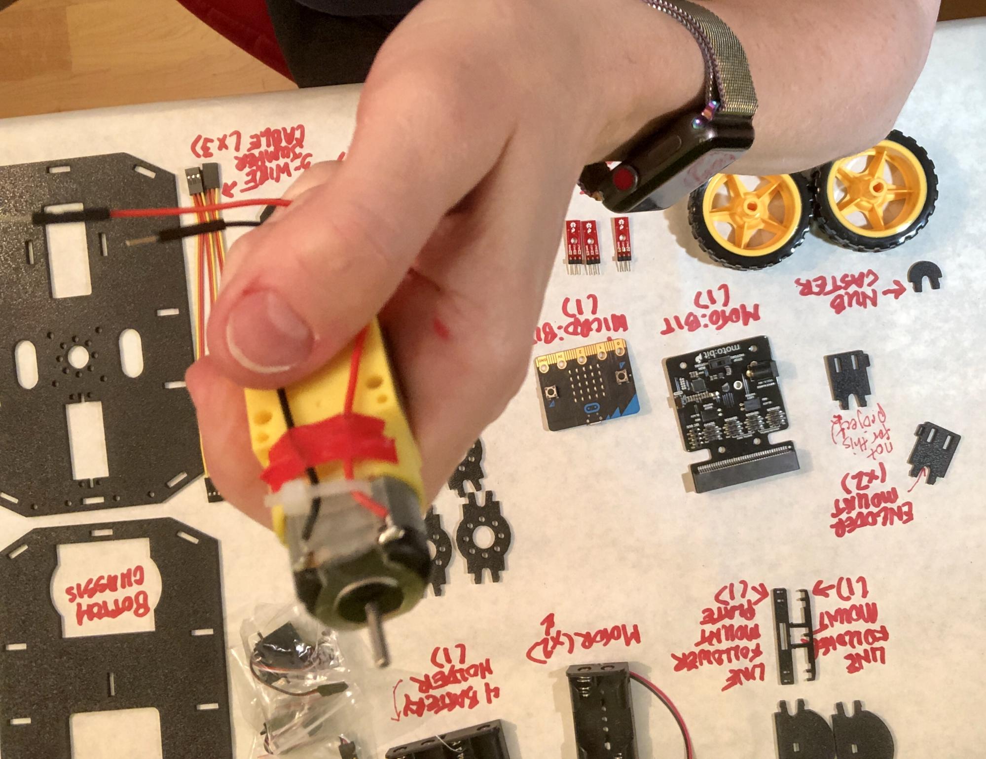
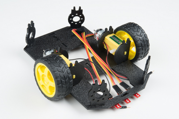
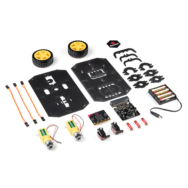
Take a look at this picture, which should show almost the same pieces you have (you will also have some cool stickers, a 6” microUSB cord, 4 AA batteries, and 2 AAA batteries):
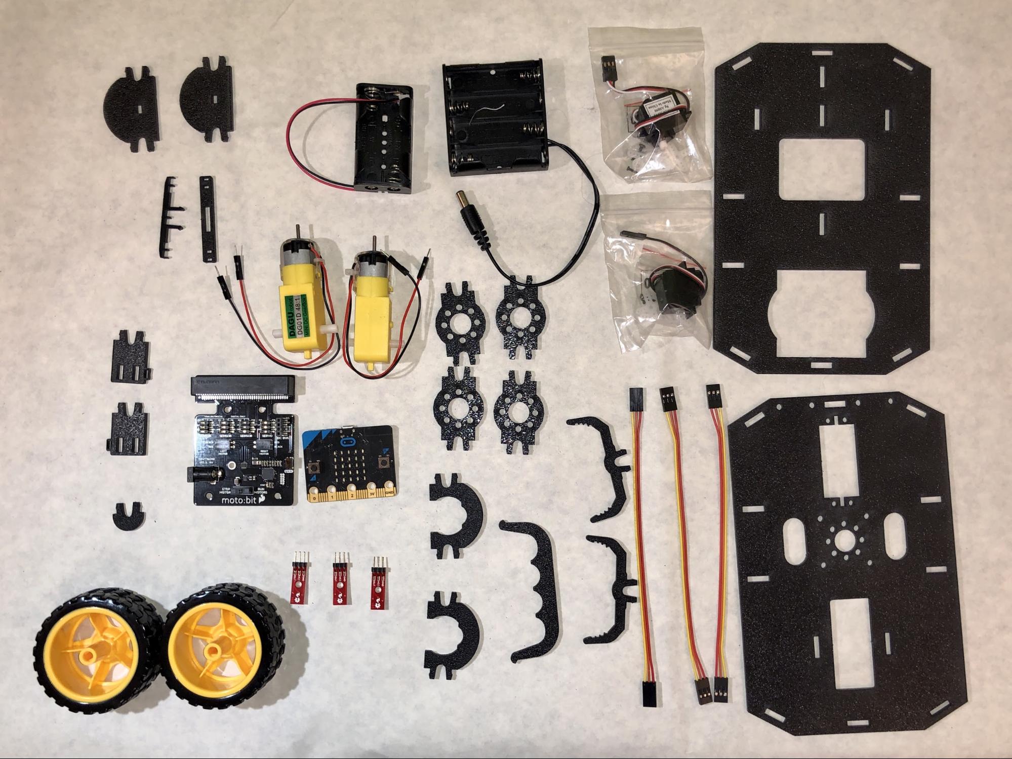
Suppose the instructions said:
Attach one side strut to each of the four corners of the bottom chassis.
(Don’t worry, these instructions will be more clear than that, we hope!)
Even if you didn’t know which part was supposed to be the “side strut” (and how could you?), you could figure it out because there’s only one part that you have four of!
This process also helps in case the manufacturer made a mistake and you’re missing a piece -- it’s easier if you find this out before you’re very-nearly-done and excited to show off your cool project.
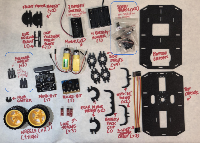
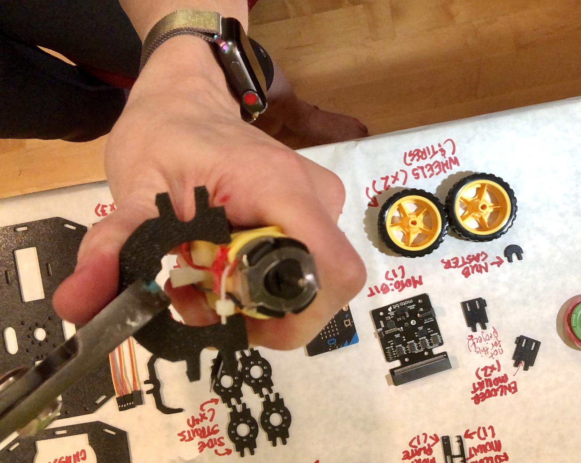
I even like to label my parts as I'm laying them out. It saves me a lot of time hunting around on my desk if everything is laid out and labeled with its name. I use a sheet of paper on top of my desk, which both helps protect my table and gives me a place to label my parts.
The final result looks something like this:
Your Robot's Major Systems
Your robot's anatomy has several major systems, which are similar to the ones that humans have:
brains -- your robot has a main brain, the micro:bit, and a "helper brain," the moto:bit, that allows the robor to do more.
a chassis - the "skeleton" of the robot that everything else (like the motors, wheels, and brains) gets attached to
the drive assembly - Not all robots move, but yours does, and "drive assembly" is the technical term for the parts of the robot that allow it to move (the motors and wheels). This is sort of like your muscle system.
sensors -- that allow your robot to "see." We'll add those sensors in this tutorial, but we'll program them and put them into use in a later tutorial.
Let’s look a little more closely at the major parts -- organs, if you will -- of your robot's anatomy before we start building.
The micro:bit
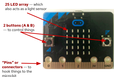
Find your micro:bit -- the "brains" of your robot. The micro:bit is packed with functionality (some of which we'll use in later tutorials). Check out the Resources and Going Further section to learn more about this microcontroller and what you can do with it.
For now, though, take a look at the features on the front
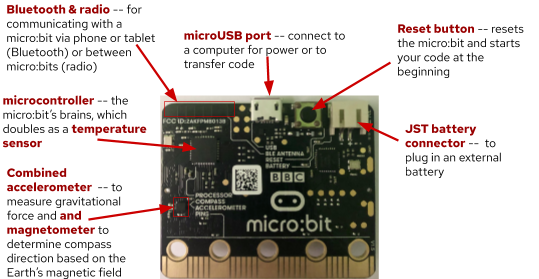
and the back...
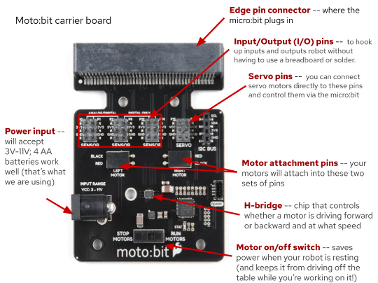
The SparkFun moto:bit
The micro:bit is pretty powerful on its own, but it can do even more when you plug it into the moto:bit, a "carrier board" which acts like a helper brain. The moto:bit can communicate with motors and can relay information from sensors back to the micro:bit. It also has a power jack that lets you attach a larger battery pack, that both allows your robot to range untethered as well as giving it the extra power the motors need.
This picture identifies the parts of the moto:bit that will be important while building your robot.
Robot Chassis
Your robot's chassis (its "skeleton") is made out of laser-cut plastic parts that we're going to put together.
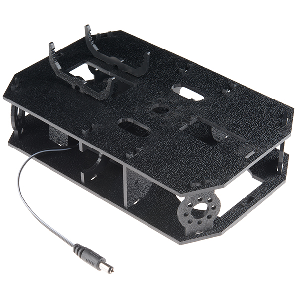
But before we can put the chassis together we need to snap out a few small parts from the two main pieces of the chassis.
You should end up with seven new-and-shiny pieces, like these...

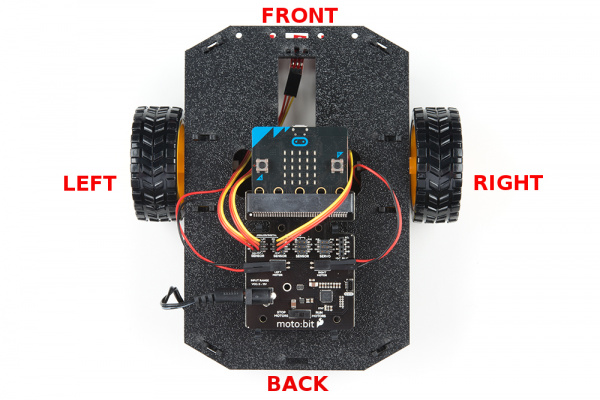
A Note on Orientation
Along with laying out, counting, identifying, and labeling all the parts in advance, I also like to do whatever I can to make things a little easier when I assemble projects. One way that I do that is by giving myself some obvious orientation clues when I’m working with parts that I might have a chance to put on upside down or backwards.
The robot instructions reference (see the picture below) * the Top Chassis and the Bottom Chassis * the “front” of the robot (the end the front bumper would be on if it had one) and the "back" * the “top” of each chassis (the textured side) and the "bottom" (the smooth side) * and the Left and Right of each chassis, which is relative to the “front”
In order to help me avoid mistakes when assembling my robot, I mark the pieces that look similar so I can easily tell the top from the bottom, the front from the back, and the left from the right.
This video shows how I marked the orientation of the chassis parts for my robot:
You can mark your parts to show the orientation in any number of ways -- by writing on one corner of each piece with a paint pen, adding a sticker, or using some tape. The important thing is to do it consistently -- if you’re marking the upper lefthand corner, do that on all the pieces. Or if you’re using a green mark to indicate the top of the part and red to indicate the bottom, do that on all the pieces.
My robot ended up looking like this:
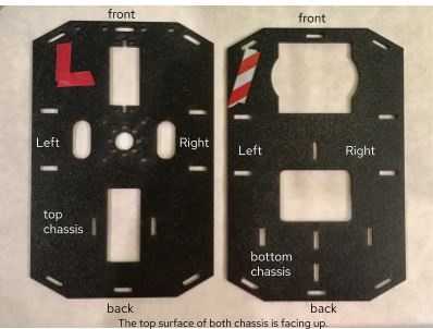
Since you have the neat stickers that came with your robot, you could use one of them to mark the front left corner (and remember which one you used!), put the other on the right front corner, then use a piece of tape to mark the Lower Chassis front left corner.
This may sound like a lot to do before you start, but if you’ve ever tried to put something together and you can’t find the right part -- or worse, you had the right part, but you put it in the wrong place or upside-down -- this will make sense.
Project checklist
☑ Read Requirements and Assemble Tools
☑ Read the Instructions (because you did, right?)
☑ Identify the Parts
☐ Build Your Project
☐ Testing
☐ Show it off!
Build: Motor Assembly
We will start at the base and work our way up in terms of our assembly strategy. What is the base of our robot? The motors and wheels!
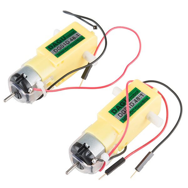
Building up this part of the chassis is probably the most tricky part of the whole process. All of the parts were designed to be snapped together and save you from needing nuts, bolts, a screw driver and wrenches. What comes with that benefit is that sometimes is the need for patience on how things fit together and maybe a bit of gentle force.
We've figured out two ways to attach the motor mounts to the motors - we're showing you both of them; choose whichever works best for you.
Option A
Hold the wires near the middle of the Motor and carefully slide a Rear Motor Mount in from the side and over the two motor wires. Be careful not to snag the wires, the cable tie, or the clear plastic strap.
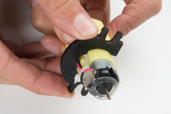
Holding the motor wires, gently twist the Rear Motor Mount counter clockwise so that it snaps in place on the motor and the wires are centered in the gap of the motor mount. Again, be sure not to snag the wires under the motor mount.
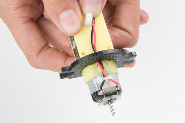
Option B (EASIER!)
Cut a short (~.75”) length of electrical tape and then cut it in half lengthwise. Hold the wires in place near the middle of the Motor, then take one of the two pieces of tape and place it over the two wires on the motor, as shown.
Use your channel lock pliers to hold the Rear Motor Mount in position directly in front of the rectangular part of the motor (as shown below) then use your pliers to help you apply pressure straight down on the Rear Motor Mount, like this:
You have to use quite a bit of force, but the Rear Motor Mount should slip over the curve of the Motor to fit snugly, while the wires pass through the small u-shaped cut in the Rear Motor Mount. The electrical tape provides a bit of a barrier as you’re applying pressure, because the edges of the Rear Motor Mount could damage the wires if you were to slip.
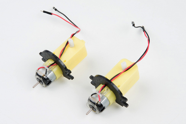
Using whichever method worked, repeat the process for the second motor, so they both look like this:
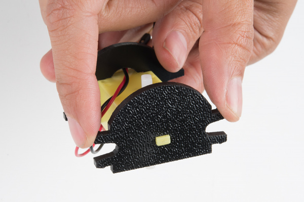
Slide a Front Motor Mount onto the protrusion on the end of one of your two Motors. Make sure the round parts of both the Front and Rear Motor Mounts are facing the same direction.
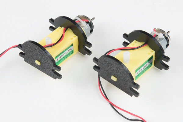
Repeat the process for the second motor. Congratulations! You have built two Motor Assemblies.
Attaching Motor Assemblies and Wheels to Chassis
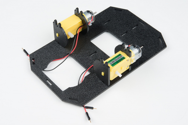
Snap one of the Motor Assemblies into the left two horizontal slots of the Bottom Chassis. Make sure that the rounded edges of the motor mounts and the wires are facing toward the center of the chassis and the metal part of the Motor Assembly faces towards the front of the Bottom Chassis. Repeat for the other motor.
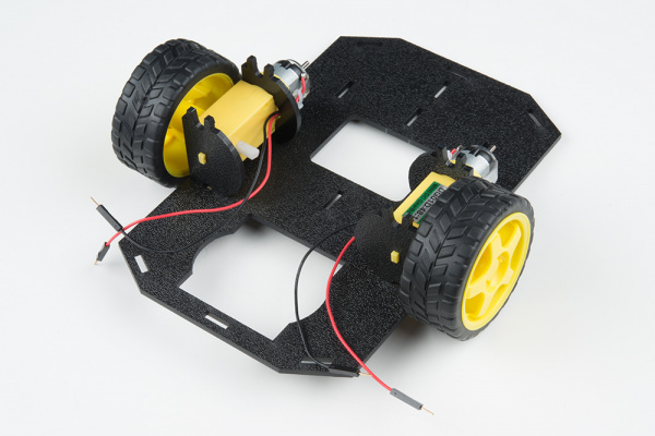
Look at one of the two white pegs (motor shafts) that stick out over the sides of your robot, and and notice that it has two flat edges. Slide one Wheel onto the Motor Shaft, making sure to line up the flat edges of the motor shaft with the flat edges of the wheel.
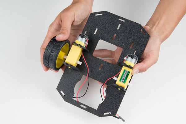
Repeat with the other wheel.
Build: Assemble line sensors
The Line Sensors (which we’re installing now, but will use in the next tutorial) emit light from an infrared LED and then detect that light once it has been reflected off an object. This allows your robot to “see” lines!
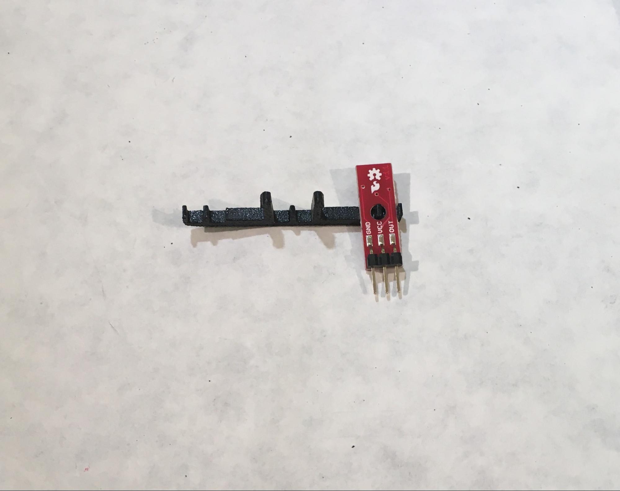
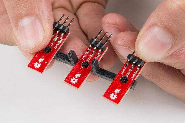
Take one of your three Line Sensors and turn it so the sensor faces down and the side with pins faces up. Attach it to the Line Follower Mount by putting the hole in the Line Sensor over the small peg on the Line Follower Mount, like this:
Repeat for the next two sensors, so that when all three are set on the Line Follower Mount, you have something that looks like this (notice that the sensors are facing away/down from the prongs of the mount):
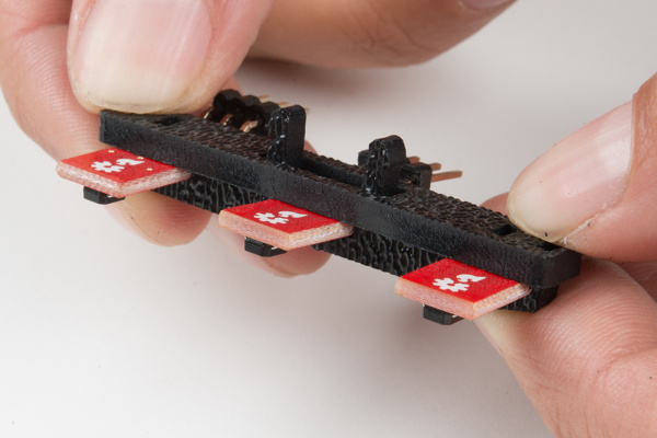
Place the Line Follower Mount Plate on top of the Line Follower Mount, sandwiching the Line Sensors in between the two. The center clip of the mount should poke through the center slot of the plate.
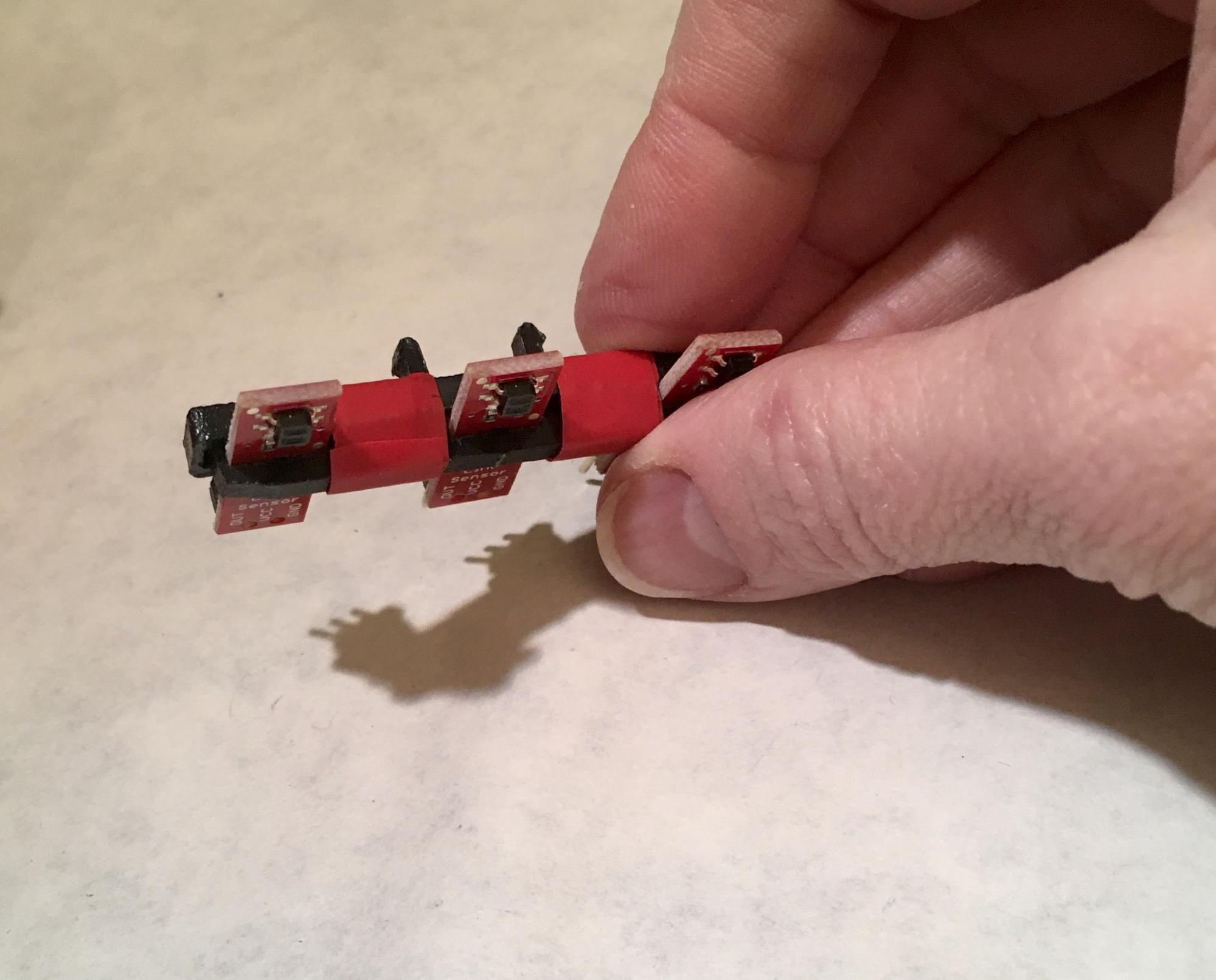
The next part is easier if you stabilize your Line Sensor sandwich (which we’re going to call a Line Sensor Array from here on out). Take a piece of electrical tape ~1.5” long, cut it in half, then wrap one piece around the entire sandwich in the gaps between the Line Sensors, like this:
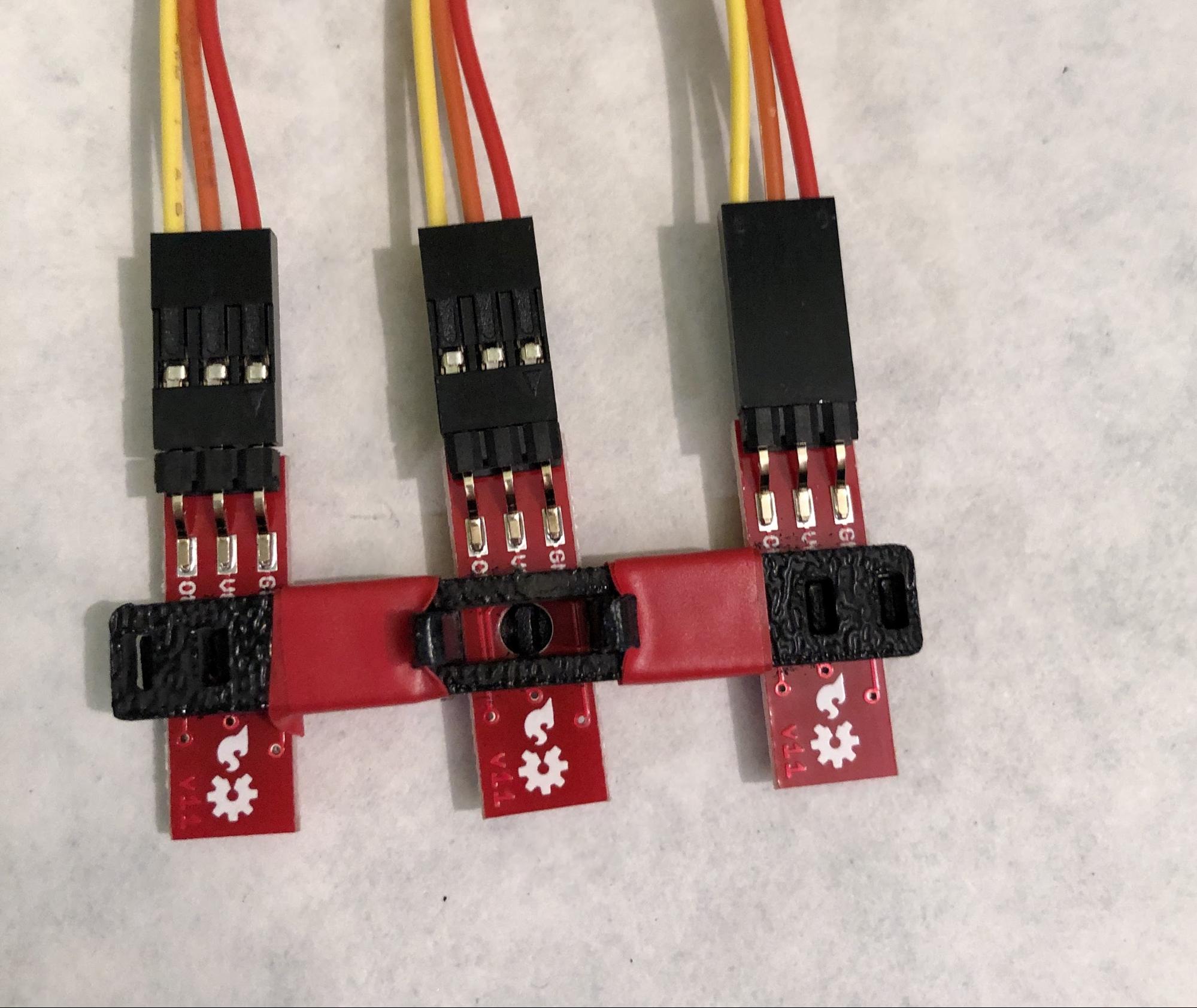
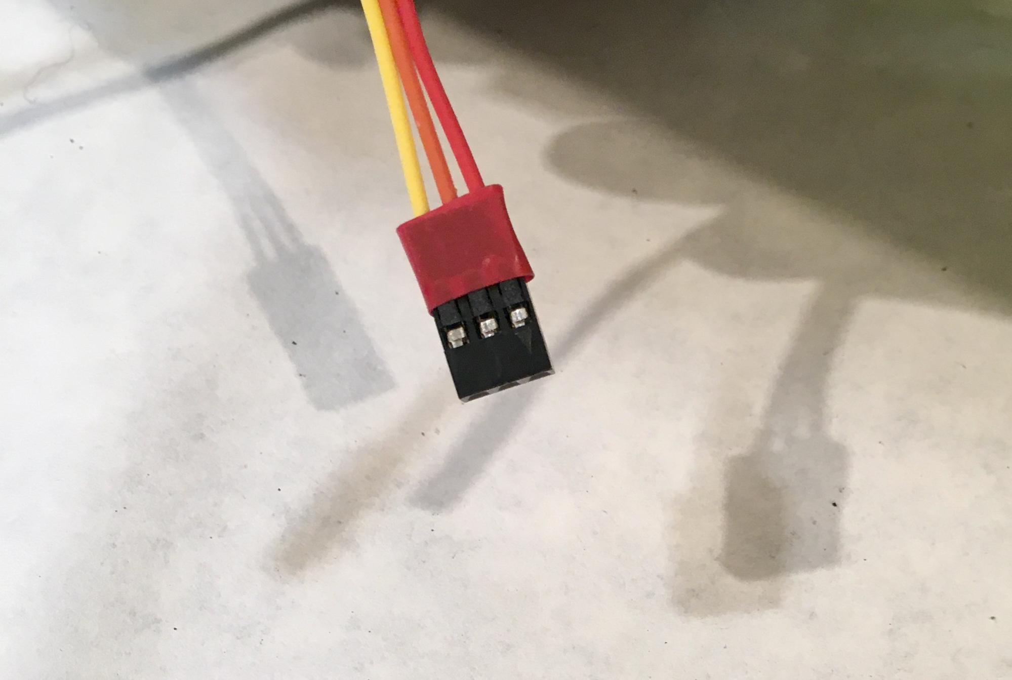
Next, you are going to connect a 3-Wire Jumper Cable to each of the Line Sensors. Note the color of the wire attached to each pin.
| Jumper Wire Color | RedBot Sensor - Line Follower |
|---|---|
| Red | GND |
| Orange | VCC |
| Yellow | OUT |
Attach all three cables to the three Line Sensors. When your Line Sensor Array is facing as shown in the picture below (the sensors face down here, as they will in the robot), the yellow wire should be on the left (on the “out” pin) and the red wire should be on the right (ground)
To attach the Line Sensor Array to the Chassis, locate the wide, rectangular slot near the front of the Lower Chassis and snap the Line Sensor Assembly in from the bottom side of the chassis. When you’re done the sensors will be facing the floor and the yellow wires will be on the left.
Route all three sets of wires through the large hole in the bottom chassis.
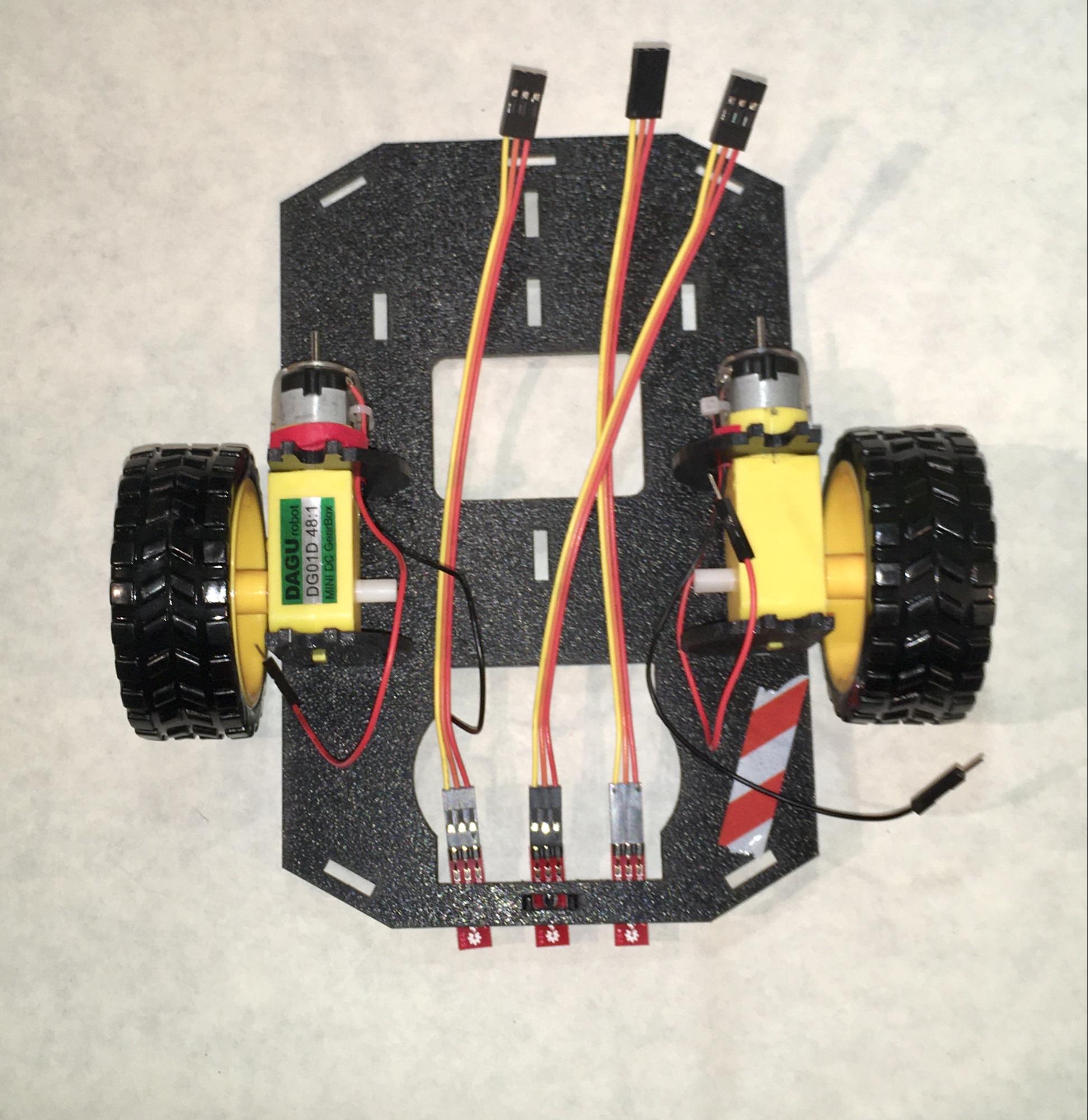
These wires will also have to pass through a single hole in the Top Chassis, and at that point it’s not easy to tell which line set of jumper cable bundles is which, so it helps if you mark the Middle Line Sensor cable before routing all the cables.
You need to mark the Middle Line Sensor cable because it and the Left Sensor bundle both get routed through the same hole on the top chassis, so they might get confused with each other. The Right Line Sensor goes through a different hole, so there’s no potential for confusion there.
The easiest way to mark the Middle Line Sensor cable is to cut a small piece of electrical tape (~.25”) and wrap it around the piece of plastic that’s at the free end of the cable bundle attached to the Middle Line Sensor.
The Middle Line Sensor cable is marked with electrical tape.
Build: Complete the Chassis
Yah! All the components are complete, so let’s move on to the final chassis assembly.
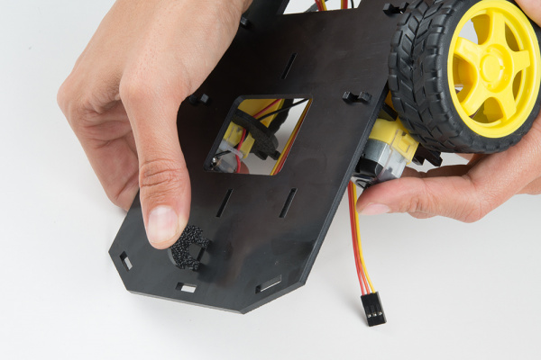
Snap the Nub Caster (go ahead, laugh. It’s a funny name) into the slot that’s closest to the back of the Bottom Chassis from the bottom side.
The Nub Caster, which keeps your robot’s tail from dragging the ground, will be on the side opposite the motors and at the other end of the chassis from the Line Sensor Array, like this:
Snap the four Side Struts, which will connect the Top and Bottom Chassis, into the diagonal slots at the corners of Bottom Chassis on the opposite side of the Nub Caster (in other words, the Side Struts are attached on top of the Bottom Chassis). Like the Nub Caster, these require a bit of force to snap into place.
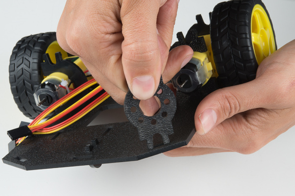
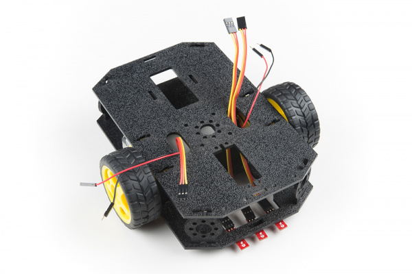
The cables for the motors and the sensor arrays should be sitting on top of the Bottom Chassis, like this:
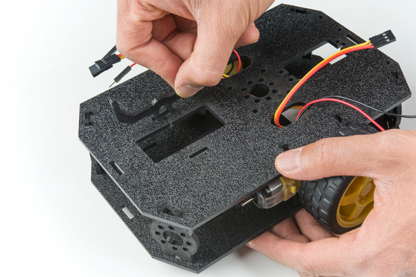
Position the Top Chassis over the Bottom Chassis -- but do not snap the two together yet. Make sure that the front ends of each chassis line up.
Route the Left Line Sensor cable bundle and the Left Motor wires (red and black) through the left oval slot in the Top Chassis.
Route the Right Line Sensor cable bundle and Right Motor wires through the right oval slot in the Top Chassis.
That just leaves the Middle Line Sensor cable, which you should also route through the left oval slot. (See why we marked that one with tape? There are two sets of Line Sensor Cable bundles that pass through that hole, and the tape helps keep them straight.) Here’s what it’ll look like:
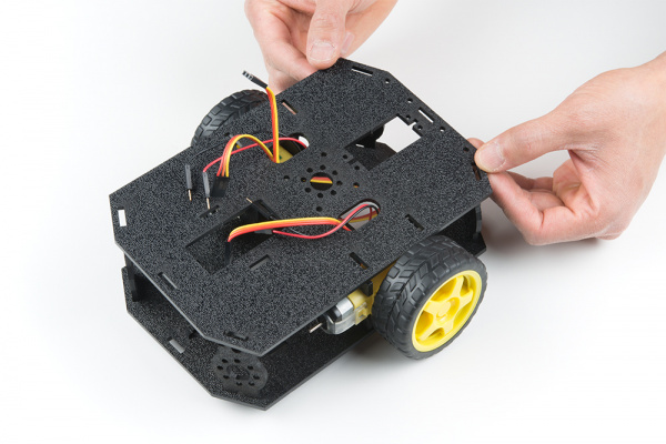
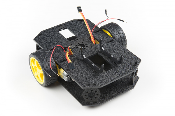
Line up the Top Chassis on top of all the struts, and carefully snap the Top Chassis assembly onto the side struts and motor mounts. Press gently above each side strut individually until they each snap into place
Build: Complete the Wiring
In this section, you will add brains of the robot: the micro:bit and SparkFun moto:bit and wire everything up for power.
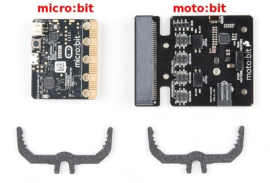
Find the micro:bit, the moto:bit, and the two moto:bit Mounting brackets.
Attach one of the moto:bit Mounts by snapping it into one of the vertical slots in the back of the top chassis near the large rectangular opening.
Attach the other moto:bit Mount by snapping it into the other slot:
Time to insert your micro:bit into the moto:bit.
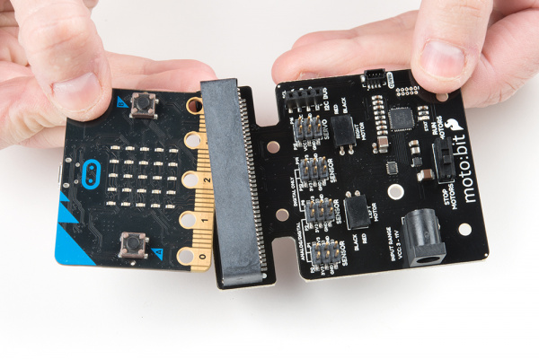
The moto:bit snaps into the second-lowest of the notches on the moto:bit Mounts. Make sure the power jack is facing the left side of the robot. Push gently and evenly until it snaps into place.
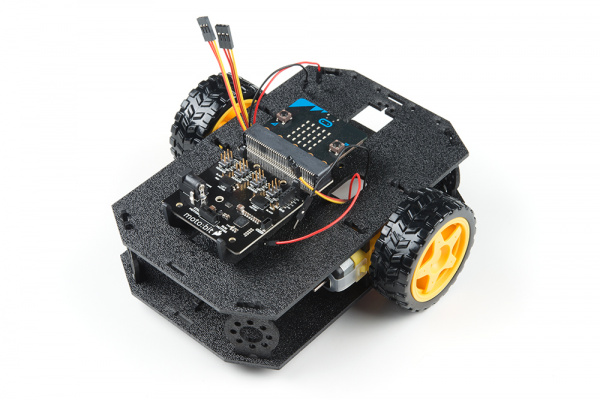
Here’s what everything looks like before connecting the wires:
To hook up the motors, put your robot in front of you with the Sensor Array pointing away from you (as if it were going to drive away from you). While you’re making your connections it’s especially helpful to be able to keep the robot oriented correctly, so if you haven’t done so already, you may want to mark the left front corner of the robot in some way.
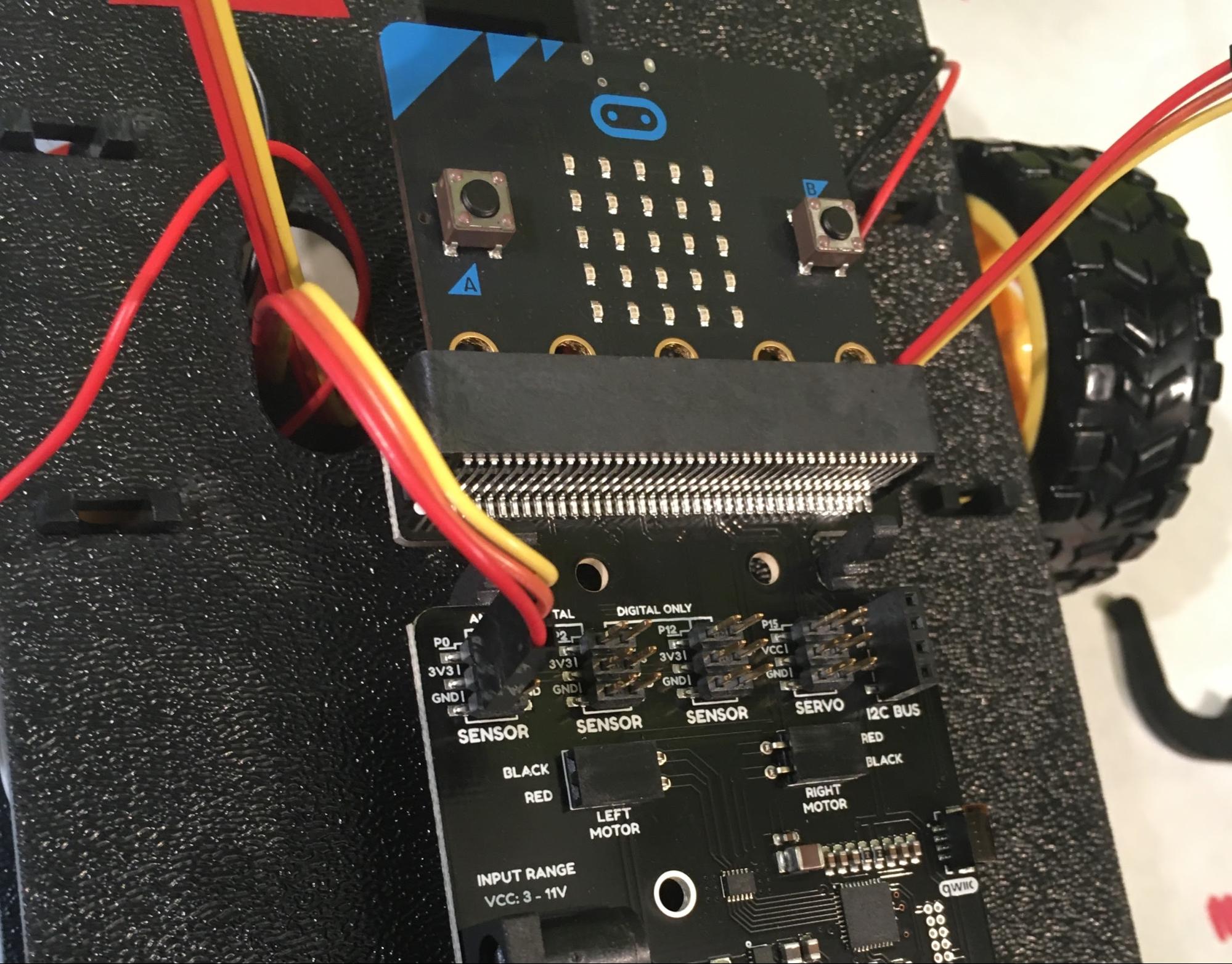
First, connect the Left Sensor cable bundle (which is the one coming out of the left oval that you didn't mark) to the moto:bit sensor pins labeled P0, 3V3, GND. Since RED was GND when we connected the cable bundle at the sensor end, RED needs to stay GND when we connect the cable bundle at the moto:bit end.
Once the cable bundle is plugged in the YELLOW wire should be closest to the front of the robot, and the RED wire should be closest to the rear of the robot, like this:
Then connect the Middle Line Sensor (the cable bundle that does have tape on it coming out of the left hole) with the pins P1, 3V3 and GND, again making sure that the RED wire stays connected to GND:

Connect the Right Line Sensor cable bundle (which comes out of the right hole) with the pins P2, 3V3, and GND
Next we’re connecting the motors, which is a little weird, but stick with me.
To make a long story short, there’s no way to determine which direction the shaft for each of your two motors will spin before getting it hooked up and running. So, what we’re going to do is hook them up the way the moto:bit board indicates for now. Once we have everything else assembled (and we’re close -- only the power is left to do after this), we’ll load some sample code and see if the motors do what we expect them to do.
If they do -- yah! If they don’t, that’s ok too -- we'll go through how to figure out which of the motor(s) is backwards and how to fix it.
Hook up the left red and black motor wires (which come out of the left hole on the Top Chassis) to the left motor connection on the moto:bit board, plugging the red wire into the hole labeled “red” and the black wire into “black”):

Connect the right red and black motor wires (coming out of the right hole) to the right motor connection on the moto:bit board in the same way:
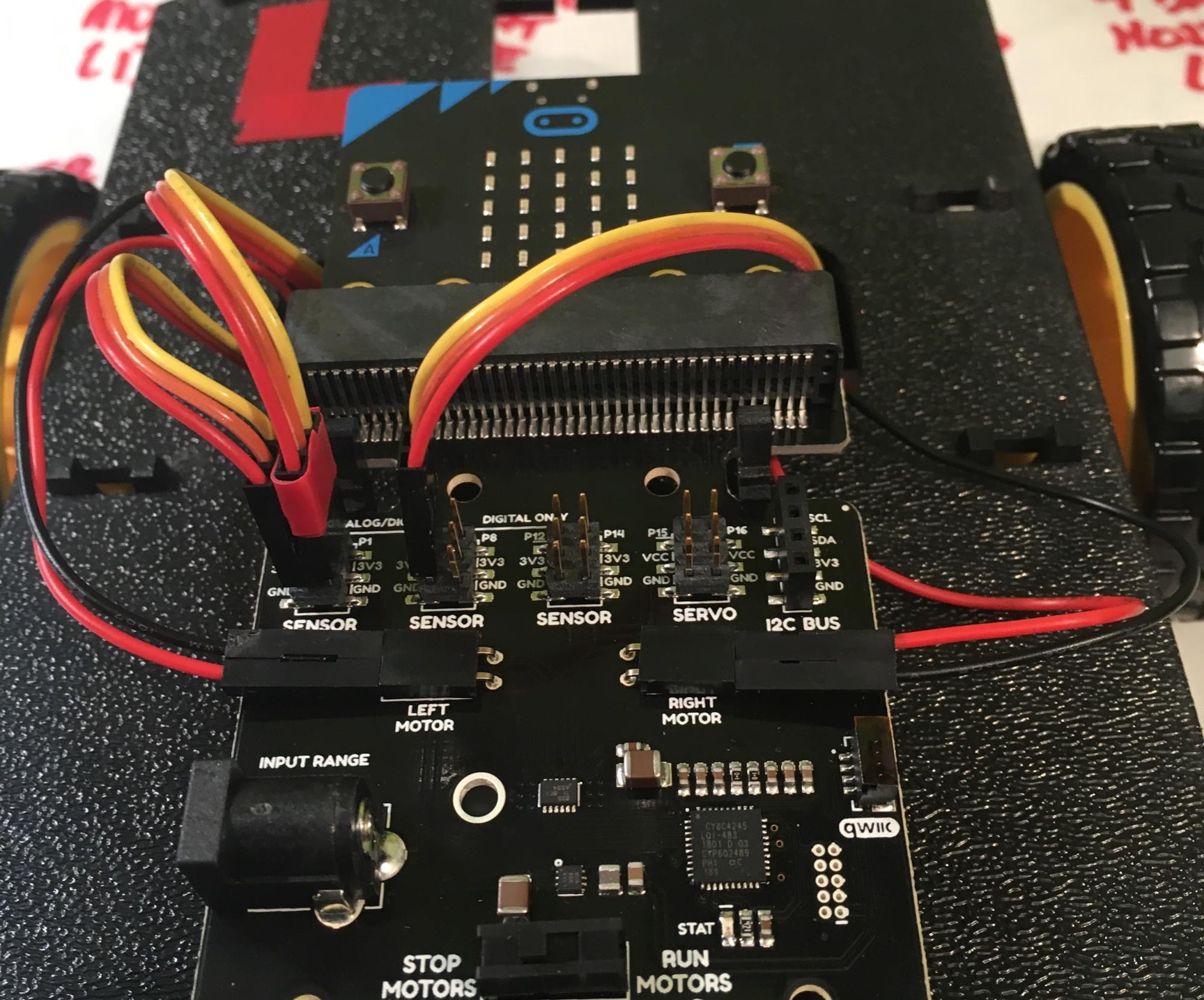
When you’re finished, you’ll have something that looks like this:
POWER!
Now we need to give your robot some juice. The power -- supplied by 4 (four) AA batteries -- goes into the moto:bit, which then powers the micro:bot. You’ll need the Battery Pack Clip , the 4 AA Battery Holder, and the provided AA batteries:
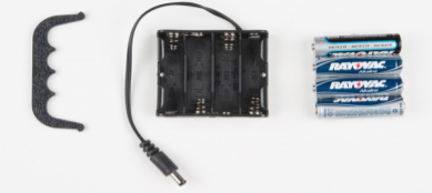
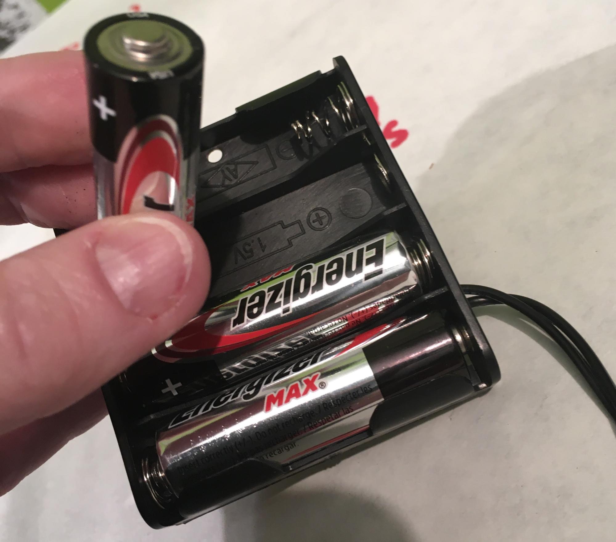
First insert the batteries into the Battery Holder, making sure that you face them in the correct direction, as shown in the diagram on the inside of the holder(the flat end of the battery, which is the negative end, goes against the spring end of the battery case):
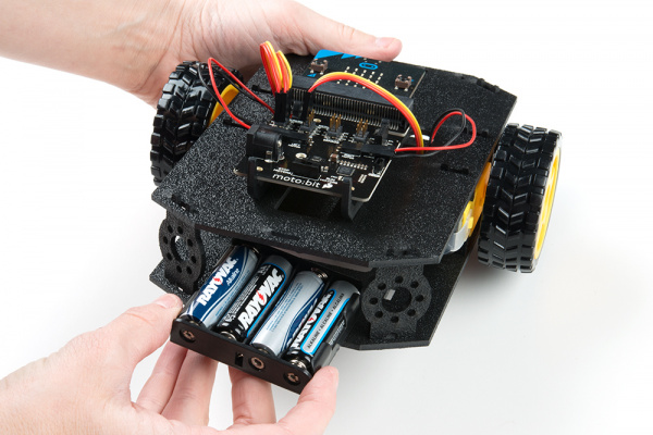
With your robot in front of you and pointing away from you, orient the Battery Holder (with batteries) as shown, then insert it into the back cavity of the chassis:
left side of the robot and the Battery holder sits on top of the hole. Insert the Battery Pack Clip on top of the battery pack (with the open end facing down towards the batteries), twist and position the clip so that it rests on top of the battery pack.
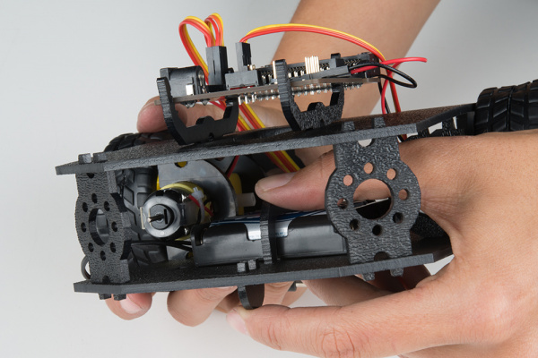
It worked best for me if I reached in through the hole nearest the sensor to hold the battery pack in place with one hand while I used the other to wiggle the Battery Pack clip into place.
Push the clip down into the vertical slots in the Bottom Chassis so it snaps in place.
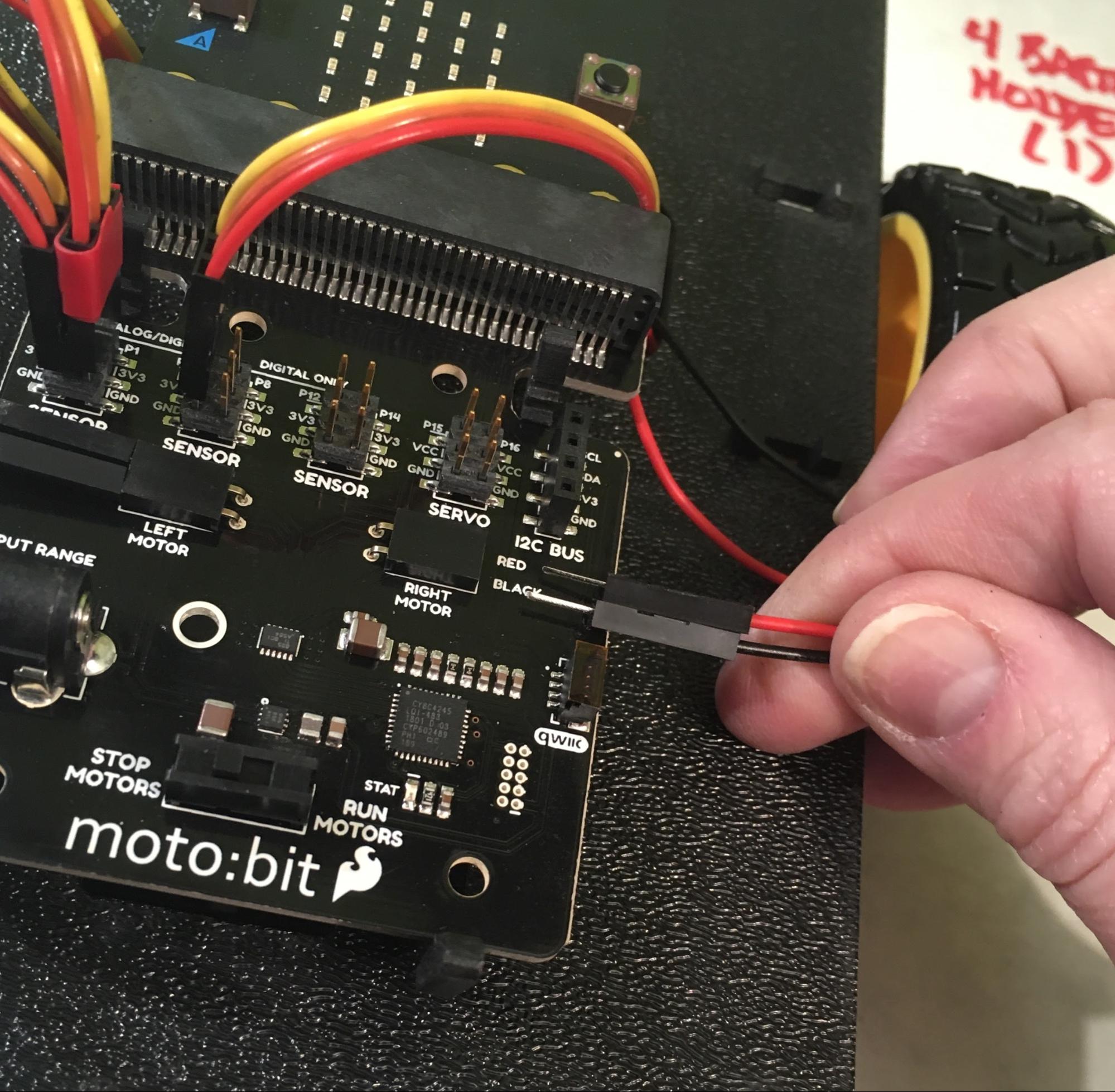
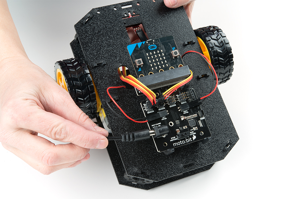
Route the barrel jack cable out of the left side of the chassis and up to the moto:bit and plug the barrel jack cable into the barrel connector on the side of the moto:bit carrier board.
Code: Give Your Robot Instructions
One of the (many) cool things about the micro:bot (and by extension, your robot), is that you can learn to control it (to program it) in several ways. We’re going to use MakeCode, which is a open source, block-based language: if you’re familiar with Scratch, it’s very similar.
MakeCode can be run in your browser or in an app (Android, iPhone or iPad). We’re going to work with the browser-based version, as it’s the easiest to set up.
Using Microsoft MakeCode
If you’ve never used MakeCode, start by visiting one of these two sites to learn the basics: how to write programs for the micro:bit, and how to connect to a micro:bit and transfer your code so that it can run.
SparkFun’s guide -- has more detail about what the different tools in the MakeCode Editor do and how the in-browser simulator works. A better choice if you prefer to read All The Directions before getting started on a project.
The Micro:bit site guide -- has a couple short videos and some brief information about how to get started with the micro:bit. If you prefer to jump right in and figure things out as you go this might be more up your alley.
No matter which introduction you choose, though, you’ll need to complete one additional step in order to access your robot’s full potential…
Installing the moto:bit MakeCode Package
In order to take advantage of the motor:bit’s full functionality, SparkFun has created an “extension,” which is a file that contains code to -- you guessed it -- extend the functionality of the original code base.
To install or add a new extension to your MakeCode toolbox (the list of different block groups), click on "Advanced" and then on "Add Extensions." This should be the last item on the list.
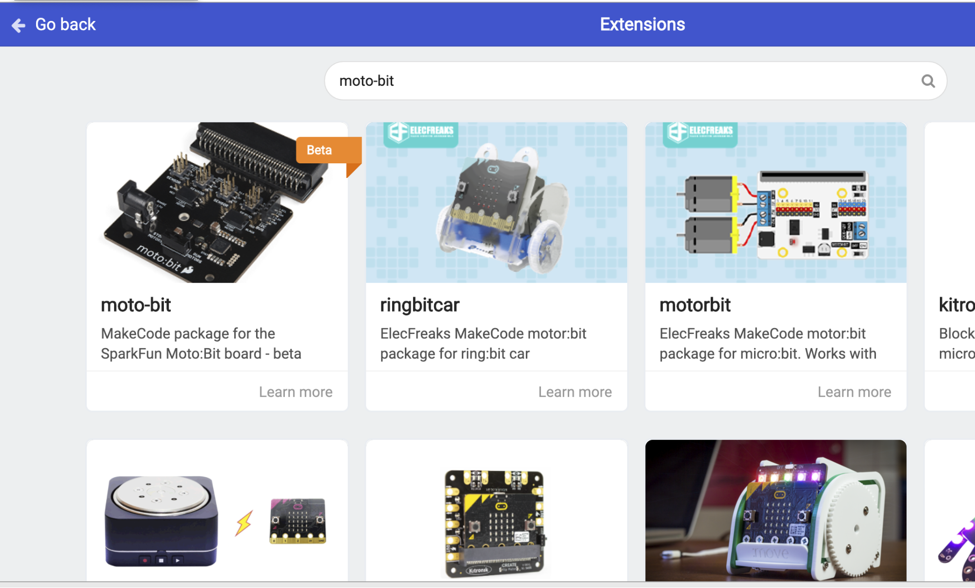
From here you can search for "moto-bit," and it should show up as a public extension in the list. Go ahead and click on it.
This will add all of the blocks to your toolbox. When you look at your toolbox you should see:
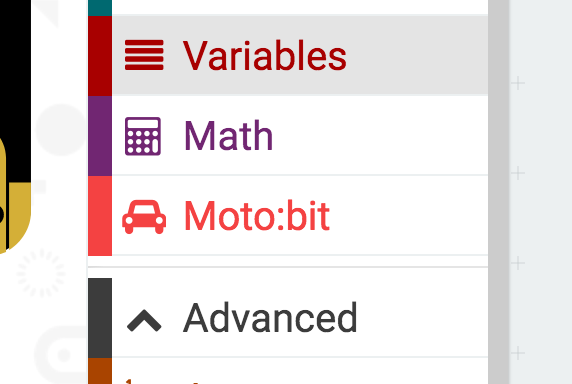
Great! You have now installed the moto:bit extension and are ready to use the board as well as the components that come in the micro:bot kit.
Load Sample Code Onto Your Bot!
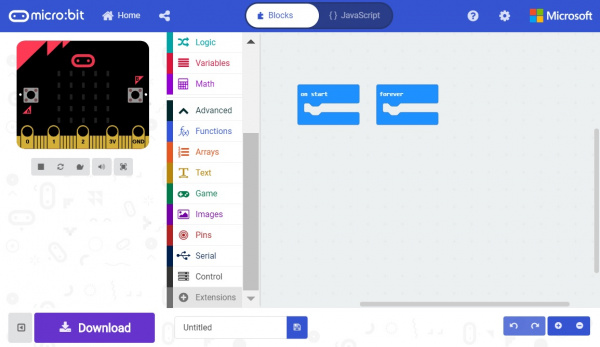
We are going to use Microsoft MakeCode to program the micro:bit. Please open a browser window and navigate to makecode.microbit.org. This should open the MakeCode environment that you used to install the moto:bit package in. (If you need to install the moto:bit package, follow the instructions to add the extension to MakeCode above.)
Or (a shortcut): if you click small square with the arrow in the upper righthand corner of the code window below it will open the code we’re going to use to get your robot running right in a new window:
Let’s look at what the code is doing...
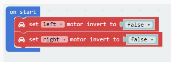
On Start
The code starts by setting each motor channel in the on start code block. Depending on how the motors are wired to the moto:bit, your micro:bot may drive in the opposite direction than what you would expect. The set ____ motor invert to ____ provides the option to switch the motor wires in code without physically rewiring the motors to the moto:bit. Set the left or right motor that you would like to invert. If you want the motor to drive in the opposite direction relative to your setup, select either true or false.
Don’t worry about this section right now -- we’ll come back to it when we see how your motors are working.
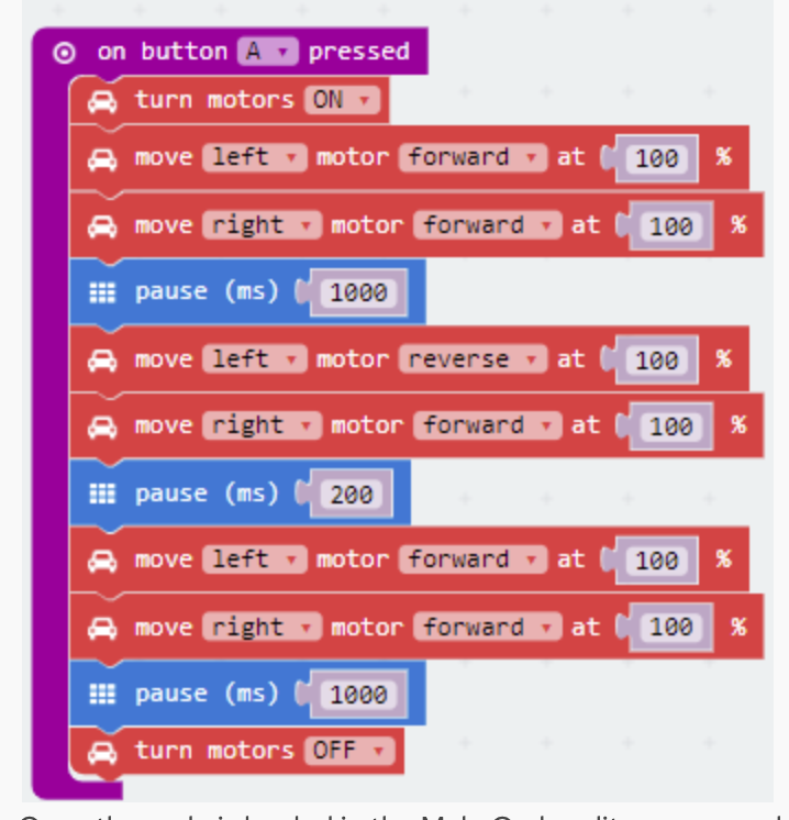
On Button Pressed
The on button __ pressed code block is an event function. Any code blocks that are placed inside of the block will only execute when that event happens. In this block, when the A button is pressed on your micro:bit your robot will start moving. When it gets to the end of the program it will stop again until you press the A button again.
Turn Motors
The turn motors __ gives you the ability to turn the motors ON or OFF in software. They are naturally OFF, so anytime you want to drive motors, you need to set them to ON. A good practice is to turn them OFF when your robot completes its task or should not be moving for long periods of time, as this saves batteries and wasted power consumption.
Move Motors At
The move ____ motor _______ at _ % block is the basis of the moto:bit software package. You use this block by selecting the values in the drop down menu:
You use this block by selecting the values in the drop down menu:
- which motor you want to control (
RIGHTorLEFT) - its direction (
FORWARDorREVERSE) - the throttle / power percentage you would like the motor to spin at (
0-100%)
For your 'bot to move forward you need to have both motors drive in the same direction.
To turn in place, or pivot, you set the motor directions opposite each other, so if one is set to go forward the other is set to go in reverse. (In the sample code, the middle two lines that say move _ left motor _ reverse _ at _ 100% and move _ right motor _ forward _ at _ 100% is a pivot turn.)
To figure out whether this code will make your robot turn to the right or to the left, stand with your arms straight out to the side, like a capital T. Now, pretend your left arm is the left motor, and your right arm is the right motor.
Now, while still keeping your arms in that capital T-shape, move your right hand forward -- like you were trying to reach something in front of you (this is like executing the move _ right motor _ forward command) -- and at the same time, move your left arm backwards (which is like move _ left motor _ reverse). If you kept that capital-T shape, what direction did your body turn?
Pause
To understand what pause does, it’s useful to remember that once you turn a motor on it won’t stop running until you turn it off.
The other thing that’s helpful is to know that this pause (ms) ___ doesn’t mean “stop what you’re doing for this amount of time” (like pushing the pause button on a music player would). Instead, it’s more like “wait this long before doing anything else.”
So, the ON and move ____ motor _______ at _ % blocks makes your motors start moving, then the pause block makes your robot wait for the length of the pause before doing anything else. And while it’s waiting for the time allocated to the pause command to pass, it just keeps on doing what it was doing before (driving).
If you want your robot to drive forward for 1 second, you set the robot's motors to drive forward and then pause for 1000 milliseconds (= 1 second) and then have the motors do something else, like stop.
Transfer the Code
Ok, now that you’ve got the code in the MakeCode editor, we need to transfer it to your robot. First, click the Download button to download the code, which will be a .hex file, to your computer.
Before transferring the code to the micro:bit, make sure the switch on the moto:bit is set to “off".
Then, use the microUSB cord to connect the micro:bit to your computer. The robot should show up as a type of device (like a drive) in your Finder.
To transfer the code to your robot, drag the .hex file onto your robot in the finder. The yellow light on the back of the micro:bit will flash rapidly while the code transfers.
Test (and fix any problems)
If your code is loaded and your robot is assembled, it’s time to take your robot for a spin.
- Unplug the USB cable (you don’t want to drag your computer off the table)
- Make sure you have plugged in the barrel power jack (and that you have batteries installed).
- Make sure the STOP/RUN MOTORS switch on the moto:bit set to RUN
- Put your robot on the floor (it would stink to have your cool, new robot drive right off the edge of a table!)
- Buckle your seatbelt and fasten your helmet and press Button A.
What we expect will happen is that your robot will drive forward for 1 second, pivot, and then drive forward for another second before stopping.
What might happen is that your robot drives backward instead of forward or it might spin in a circle! -- what!?
No, you didn’t do anything wrong; sometimes wiring is weird.
If you want to go ahead and fix it skip down to the fixing motor issues section. (No judgement!)
If you’d like to learn a little more about how motors work (and how engineering happens) before fixing it, read on:
Motors work by sending current around a coil of wire, creating a magnetic field (30-sec video showing this in action). This then interacts with magnets in the motor, causing a push / pull effect. If you do that with proper spacing and timing, then you can spin a shaft. (Check out the Resources section for a longer video on how motors work.)
When we hooked up the motors to the moto:bit board, we did so with the assumption that the red wire is the positive (+) and the black wire is the negative (-), which is the standard (also called the “convention”) and that the current would flow through the coil inside the motor from the positive (+) red end to the negative (-) black end. That would cause the shaft to spin in one direction (clockwise, normally). The motor also has a gearbox that both turns the clockwise spin 90° (so the drive shaft sticks out the side of the motor rather than the front -- much more handy for mounting wheels) and turns a very fast, but fairly weak spin into the slower but more powerful spin that’s needed to make your robot go.
So, what happens if:
- the factory occasionally makes a batch of motors with the black positive (+) and the red negative (-) -- and yes, this sometimes happens! and
- you wire the motors following the markings on the moto:bit board (which was engineered based on the standard red is always positive (+) and black is negative (-)), and
- you run the code as written?
In this case, your robot won't behave as expected, but that’s ok, because we can fix it!
Diagnosing Motor Issues
If your robot is driving backwards, it means you got two “reverse” motors.
If your robot is spinning in a circle (which is kind of cute, but not what we’re looking for), then you got one normally wired motor and one “reverse” motor.
Either way, you have to compensate for the “reverse” motor(s), which you can do in the software or in the hardware.
We’ll look at both (and you can try them both), but if I have a choice, I’ll usually try to find a hardware fix that I can use on a permanent basis because there’s less chance that it will interfere with something else I might want to do in my code later on.
But what if you’re not sure whether there’s a reverse-motor situation happening? (Or you're not sure which motor is reversed...)
That's where the software fix comes in handy. You can make the necessary fix in the software, test that, then if it turns out that you have (one or more) reverse motors, you can make a more permanent fix with hardware. Because it’s useful to diagnose a problem before making fixes, we’re going to look at the software fix first.
Reversed-Motor Software Fix
If you closed it, open your MakeCode window again. Let's look at that first block of the sample code with the set ____ motor invert to ____ in it.
Here's how we described what was happening in that block:
On Start
The code starts by setting each motor channel in the on start code block. Depending on how the motors are wired to the moto:bit, your micro:bot may drive in the opposite direction than what you would expect. The set set ____ motor invert to ____ provides the option to switch the motor wires in code without physically rewiring the motors to the moto:bit. Set the left or right motor that you would like to invert. If you want the motor to drive in the opposite direction relative to your setup, select either true or false.
But what do you do if your robot is...
Spinning in a Circle
Here's my first test run:
- Try setting either of the two motors to
trueinstead offalse. It doesn’t matter which you choose. - Download the code and transfer it to your micro:bit like you did before.
- Press the A button and see what happens. If your robot now goes backwards then your random choice of which motor to change was the wrong one. In other words, you reversed the motor that was correctly wired. :-) Like I did here (test run #2):
- No problem, though, just repeat the process, returning that motor to
falseand setting the other motor totrue. Then download your code to the robot and try it out. Here's my test run #3: - Hopefully your robot is now driving in the right direction?
- Congratulations! You correctly identified the reversed motor, and you can (if you’d like) fix the motor in the hardware. Don’t forget to change the software back to its original state!
Running in Reverse
If your robot is running backwards:
- Try setting both motors to
trueinstead of false. - Download the code and transfer it to your micro:bit like you did before.
- Press the A button and see what happens.
- Hopefully your robot is now driving in the right direction?
- If so, congratulations -- you got two reversed motors, and you figured it out!
- Now you can (if you’d like) fix the motors in the hardware. Don’t forget to change the software back to its original state!
Reversed-Motor Hardware Fix
Once you've used the software fix to figure out which motor(s) are reverse-wired, then you can make the change more permanently by changing the way the wires are connected.
Example: Let’s say your robot was spinning, and you used the software fix to figure out that your left motor is reversed. To fix it in the hardware, you’d plug the red wire into the pin that’s labeled black on the moto:bit on the left side and the black wire into the pin labeled red on the moto:bit on the left side. (Don’t forget to go back into your code and reset the left motor invert to false. Then you would download your new code and re-test it.)
If your robot is driving backwards, it’s the same process as for the spinning robot, only you have to reverse the sets of wires on both the right and left sides of the moto:bit (and change, re-download, and test your code).
Here's my recap of the entire testing process and final run:
Project checklist
☑ Read Requirements and Assemble Tools
☑ Read the Instructions
☑ Identify the Parts
☑ Build Your Project
☑ Testing
☐ Show it off!
Congratulations! You have an amazing Co.Lab robot -- we can’t wait to see what you do with it.
What’s next?
More fun things to do with your Co.Lab robot kit (we’re going to use those Line Sensors you installed)!
Keep an eye on this space as we’ll be releasing more activities over time!
Troubleshooting
| If your robot won’t move... | Make sure you have power!
You should see a red blinking light on the moto:bit where it says “STAT” (status). If not, then...
|
| The Moto:bit tools don’t show up in MakeCode... | Try installing them again from the add package option in MakeCode |
| You don’t see the Micro:Bit on your computer when you go to transfer your code |
|
| Your robot is spinning in a circle or running in reverse... | Follow the steps under Fixing Motor Issues section? |
| Your robot isn’t driving in a straight line… | Look at the lines in the code where you tell each motor what to do:
move _____ motor _____ at__ %
This command tells the robot which motor to move (RIGHT or LEFT), which direction to move it (FORWARD or REVERSE), and at which throttle / power percentage to spin it (0-100).
By adjusting the throttle / power percentage of the two motors relative to each other you can make one “stronger” than the other. So, for instance, if your robot lists to the left you can turn your right motor “down” to 90% power and leave your left motor at 100%. Play with the amounts to see how much correction your motors need. |
Changing Batteries
When you find that you need to replace the batteries in the micro:bot, first unplug the battery pack from the moto:bit.
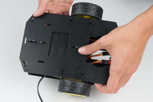
Turn the micro:bot over and push on the Battery Holder through the hole in the Bottom Chassis. This will cause the Battery Pack Clip to unsnap from the Bottom Chassis.
Slide the Battery Pack and Clip out from the back of the micro:bot.
Change the batteries, then follow the steps in the “Attach Battery Pack” section above to put the Battery Pack back in the micro:bot.
Resources and Going Further
For more information about the moto:bit, check out the resources below:
We produce a number of other kits and carrier boards that you can hook up to your micro:bit to help take your projects to the next level. We have dedicated an entire page for you to explore where you can go from here with the micro:bit
Here is some further reading that may help you along in learning more about the world of electronics.
For more information on our micro:bit ecosystem, check out these tutorials:
micro:bit Breakout Board Hookup Guide
Getting Started with MicroPython and the SparkFun Inventor's Kit for micro:bit
SparkFun gator:bit v2 Hookup Guide
SparkFun gator:soil Hookup Guide
For more robot fun, check out our these other tutorials that use the micro:bit ecosystem.
micro:bot Kit Experiment Guide
Wireless Remote Control with micro:bit
Full Kit Contents List
If you haven't yet picked up one of the Red Hat Robotics kits and want to get started you can find the robot here
Red Hat Co.Lab Robot Kit
CUST-16424Things sometimes break or get lost, its part of making and tinkering! If you need to replace a part here is a list of the individual components that make up the Red Hat Robotics Kit from the SparkFun catalog.
Master Connection List
This table shows you how things are connected. On the left side of the table is the board (the moto:bit in this case), in the middle is the color jumper wire, and in the right column is the “far end” connection (either one of the motors or one of the Line Sensors). This is a kind of shorthand for the step-by-step instructions that tell you exactly where each end of each connection goes, so sometimes instructions will give you a table like this rather than step-by-step instructions
Left Line Sensor
| SparkFun moto:bit Pins | Jumper Wires | Left Line Follower Board |
|---|---|---|
| P0 | 3-Wire Jumper Cable - Yellow | OUT |
| 3.3V | 3-Wire Jumper Cable - Orange | VCC |
| GND | 3-Wire Jumper Cable - Red | GND |
Middle Line Sensor
| SparkFun moto:bit Pins | Jumper Wires | Center Line Follower Board |
|---|---|---|
| P1 | 3-Wire Jumper Cable - Yellow | OUT |
| 3.3V | 3-Wire Jumper Cable - Orange | VCC |
| GND | 3-Wire Jumper Cable - Red | GND |
Right Line Sensor
| SparkFun moto:bit Pins | Jumper Wires | Right Line Follower Board |
|---|---|---|
| P2 | 3-Wire Jumper Cable - Yellow | OUT |
| 3.3V | 3-Wire Jumper Cable - Orange | VCC |
| GND | 3-Wire Jumper Cable - Red | GND |
Left Motor
| SparkFun moto:bit Pins | Left Motor Jumper Wires |
|---|---|
| LEFT MOTOR - RED | Soldered on Motor Jumper Wire - RED |
| LEFT MOTOR - BLACK | Soldered on Motor Jumper Wire - BLACK |
Right Motor
| moto:bit Pins | Right Motor Jumper Wires |
|---|---|
| RIGHT MOTOR - RED | Soldered on Motor Jumper Wire - BLACK |
| RIGHT MOTOR - BLACK | Soldered on Motor Jumper Wire - RED |
License and Credit
| Author(s) | Gina Likins, borrowed heavily from an activity written by SparkFun Electronics |
| Source | SparkFun micro:bot guide https://learn.sparkfun.com/tutorials/microbot-kit-experiment-guide |
| License | Co.Lab License Information
Co.Lab uses two different licenses for our files:one for Content, like the Activity itself, and one for Code, whether downloadable or presented as excerpted source code in documentation.ContentCopyright © SparkFun. Modifications © 2020 Red Hat. Except where otherwise indicated, this document and the photos contained in this document are licensed under Creative Commons Attribution-ShareAlike 4.0 International. Modifications of this work may not include the Red Hat or Co.Lab logos, other than as they may appear in photos of Project Artifacts. “Project Artifacts” means the tangible physical artifacts included with the Co.Lab Robot Kit, such as postcards, stickers and packaging. License: Co.Lab content is released under Creative Commons Attribution-ShareAlike 4.0 International Note: This is a human-readable summary of (and not a substitute for) the license. A copy of the Creative Commons Attribution-ShareAlike 4.0 International license can be found here: "https://creativecommons.org/licenses/by-sa/4.0/legalcodeYou are free to: Share — copy and redistribute the material in any medium or format. Adapt — remix, transform, and build upon the material for any purpose, even commercially. The licensor cannot revoke these freedoms as long as you follow the license terms. Under the following terms:Attribution — You must give appropriate credit, provide a link to the license, and indicate if changes were made. You may do so in any reasonable manner, but not in any way that suggests the licensor endorses you or your use.ShareAlike — If you remix, transform, or build upon the material, you must distribute your contributions under the same license as the original. No additional restrictions — You may not apply legal terms or technological measures that legally restrict others from doing anything the license permits. Notices:You do not have to comply with the license for elements of the material in the public domain or where your use is permitted by an applicable exception or limitation. No warranties are given. The license may not give you all of the permissions necessary for your intended use. For example, other rights such as publicity, privacy, or moral rights may limit how you use the material.Code Unless otherwise specified, all Code for the Co.Lab Robot Kit project is available under the terms of the MIT license. The MIT License (MIT) Copyright © 2020 Red Hat Permission is hereby granted, free of charge, to any person obtaining a copy of this software and associated documentation files (the "Software"), to deal in the Software without restriction, including without limitation the rights to use, copy, modify, merge, publish, distribute, sublicense, and/or sell copies of the Software, and to permit persons to whom the Software is furnished to do so, subject to the following conditions: The above copyright notice and this permission notice shall be included in all copies or substantial portions of the Software. THE SOFTWARE IS PROVIDED "AS IS", WITHOUT WARRANTY OF ANY KIND, EXPRESS OR IMPLIED, INCLUDING BUT NOT LIMITED TO THE WARRANTIES OF MERCHANTABILITY, FITNESS FOR A PARTICULAR PURPOSE AND NONINFRINGEMENT. IN NO EVENT SHALL THE AUTHORS OR COPYRIGHT HOLDERS BE LIABLE FOR ANY CLAIM, DAMAGES OR OTHER LIABILITY, WHETHER IN AN ACTION OF CONTRACT, TORT OR OTHERWISE, ARISING FROM, OUT OF OR IN CONNECTION WITH THE SOFTWARE OR THE USE OR OTHER DEALINGS IN THE SOFTWARE. |