Fingerprint Scanner (GT-521Fxx) Hookup Guide
 bboyho
 Introduction
Have you ever wanted to add fingerprint identification to your project? SparkFun offers a fingerprint scanner from ADH Tech designed to do just that! The GT-521F32 and GT-521F52 includes an optical sensor for reading fingerprints and a processing IC with built-in fingerprint algorithms. Here you will find information about connecting the fingerprint scanner and how to use it with Hawley's FPS_GT511C3 library.
Fingerprint Scanner - TTL (GT-521F32)
SEN-14518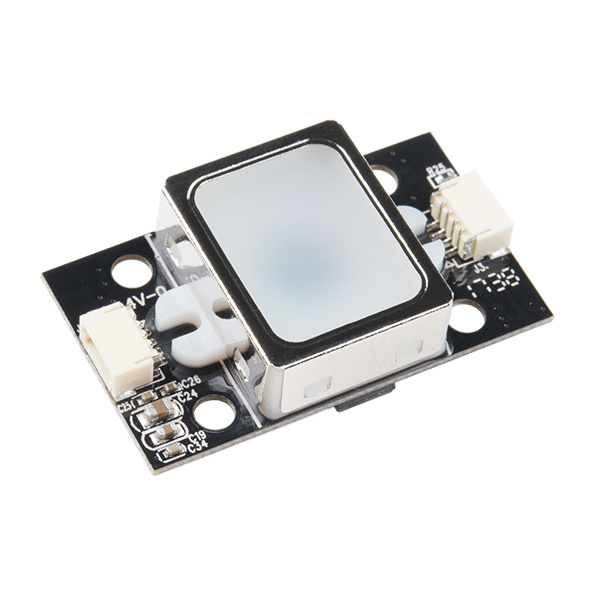
Suggested Reading
Depending on how you are connecting to the fingerprint scanner, you may need to know the following concepts before working with one of these boards:
How to Solder: Through-Hole Soldering
Serial Communication
Installing an Arduino Library
Logic Levels
Serial Terminal Basics
Hardware Overview
Features
The GT-521F32 and GT-521F52 have a lot in common with the previous models. They have the same protocol commands and packet structure. Code that was implemented for previous models should be functionally the same. The fingerprint scanner has the ability to:
- Enroll a Fingerprint
- Identify a Fingerprint
- Capable of 360° Recognition
However, there are a few differences in the boards. These include:
- Different Board Layout
- 4x Mounting Holes
- 2x JST SH Connectors
- Touch Interface
One significant difference to keep in mind when integrating the fingerprint scanner in a project is the number of fingerprints that the device can hold. The GT-521F32 costs less but it can hold only 200 fingerprints. The GT-521F52 is slightly more expensive but it can hold 3000 fingerprints.
| Technical Specs | GT-521F32 / GT-521F52 |
|---|---|
| CPU | ARM Cortex M3 Cortex |
| Sensor | optical |
| Window | 16.9mm x 12.9mm |
| Effective Area of the Sensor | 14mm x 12.5mm |
| Image Size | 258x202 Pixels |
| Resolution | 450 dpi |
| Max # of Fingerprints | 200 / 3000 |
| Matching Mode | 1:1, 1:N |
| Size of Template | 496 Bytes(template) + 2 Bytes (checksum) |
| Serial Communication | UART (Default: 9600 baud) and USB v2.0 (Full Speed) |
| False Acceptance Rate (FAR) | < 0.001% |
| False Rejection Rate (FRR) | < 0.01% |
| Enrollment Time | < 3 sec (3 fingerprints) |
| Identification Time | <1.5 |
| Operating Voltage | 3.3V ~ 6Vdc |
| Operating Current | < 130mA |
| Touch Operating Voltage | 3.3Vdc |
| Touch Operating Current | < 3mA |
| Touch Standby Current | < μ5 |
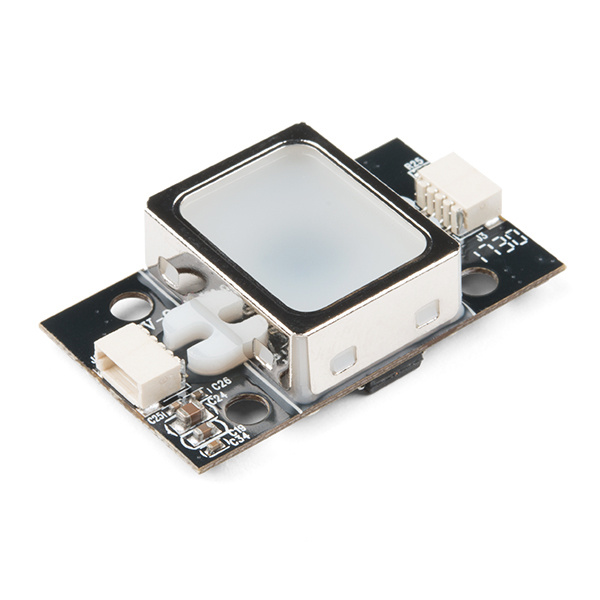
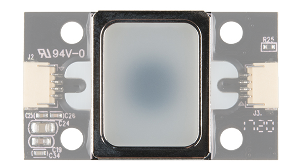
The image below shows the fingerprint scanner's optical sensing area where the device will be able to scan your fingerprint.
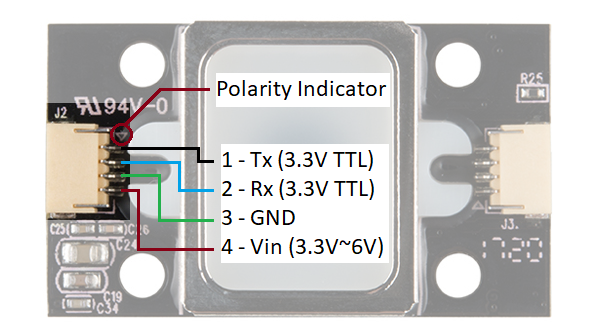
There is a marking next to the JST-SH connector that indicates polarity. The JST-SH connector breaks out the pins for serial UART and power. While the input voltage is between 3.3V and 6V, the UART's logic level is only 3.3V. You will need a logic level converter or voltage divider to safely communicate with a 5V device.
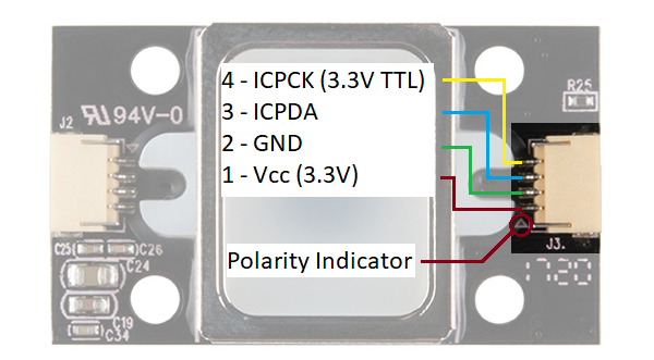
The GT-521F32 and GT-521F52 have the ability to sense if a finger is placed on the optical sensing area. Upon contact with the metal frame around the optical sensing area, the ICPCK will output 3.3V (HIGH). Otherwise, the ICPCK will be 0V (LOW)
| Touch State | ICPCK Pin Status |
|---|---|
| Finger Initially Touching the Frame | LOW => HIGH |
| No Finger Touching | LOW => LOW |
| Finger Touching the Frame | HIGH => HIGH |
| Removing a Finger From the Frame | HIGH => LOW |
Hardware Hookup
The fingerprint scanner requires a serial UART connection and power. There are a few options to connect to the sensor depending on what UART device you are using. The easiest would be to use an FTDI but you can also use any microcontroller that has a UART.
1.) Connecting w/ a 3.3V FTDI
Option 1: Qwiic Cable
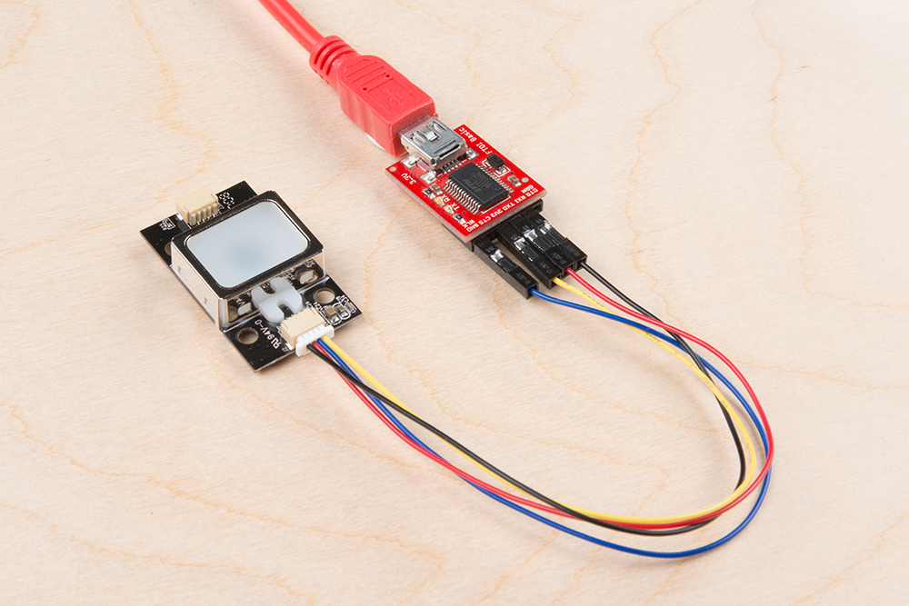
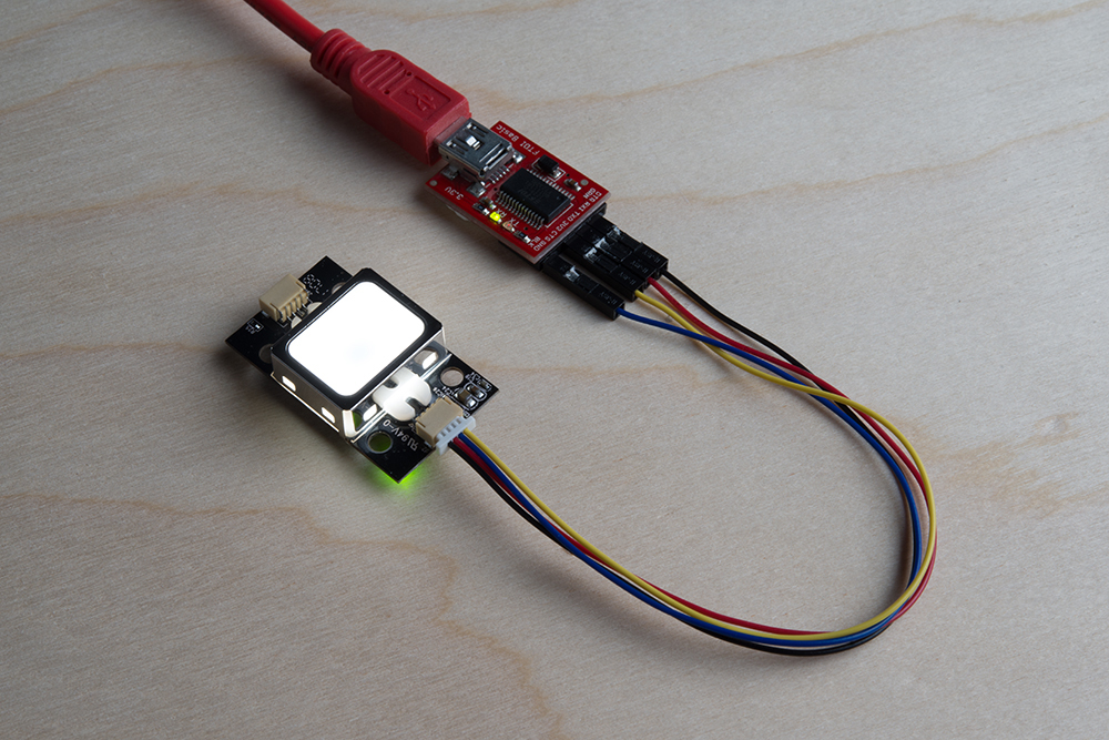
To connect the fingerprint scanner to your computer, it is recommended to connect the JST SH cable to a USB-to-serial converter. Here are the minimum required parts you would need to get started:
- Fingerprint Scanner (GT-521F32 or GT-521F52)
- Qwiic Cable - Breadboard Compatible
- 3.3V FTDI Basic Breakout
- Mini-B USB Cable
Below are the following connections you would need to make with the JST-SH connector labeled as J2:
| Fingerprint Scanner [Pin #] | FTDI 3.3V |
|---|---|
| UART_TX (3.3V TTL) [Pin 1] | RX |
| UART_RX (3.3V TTL) [Pin 2] | TX |
| GND [Pin 3] | GND |
| Vin (3.3V~6V) [Pin 4] | 3.3V |
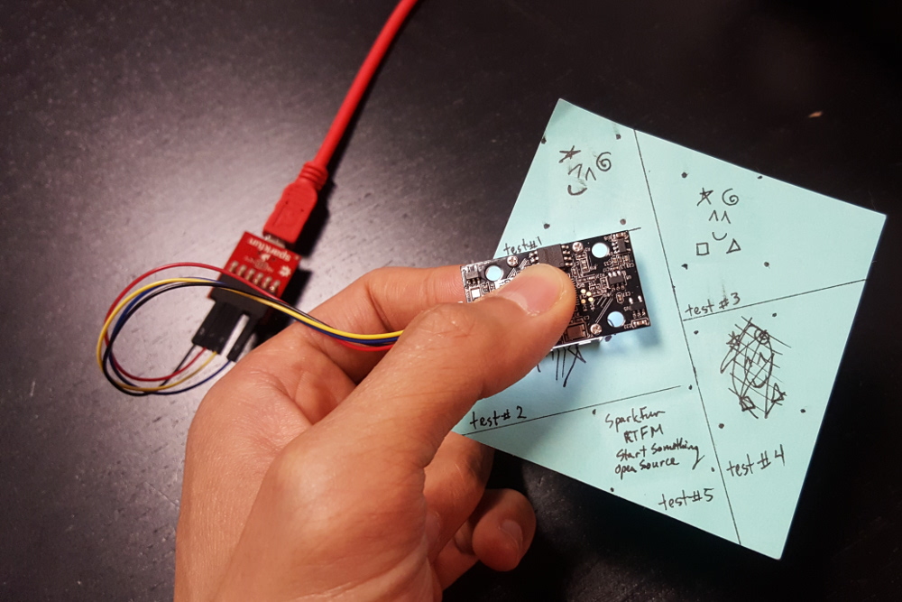
After connecting, the setup should look like the image below.
Option 2: Making a Custom Adapter
If you are using the JST SH Jumper 4 Wire Assembly instead of the Qwiic cable, it is highly recommended that you make a custom adapter by soldering to the ends of the wire for a secure connection. This will ensure that the connection is not loose when inserting it into female header sockets of an FTDI or the RedBoard/Arduino Uno. The cable wire is small compared to the female header socket. A small bump can mess with the serial UART or power between the fingerprint scanner and converter. This may require you to reconnect the scanner to your computer or device. Making an adapter will also provide quick access to the small 4-pin JST-SH connector that is on the scanner.
For more information on how to make a custom adapter, please refer to the older tutorial. Remember, the pin locations are the same so the adapter can work with the current fingerprint scanner.
2.) Connecting w/ a 5V Arduino
Before using the Arduino's example code, make sure that the logic levels match. If you are using a 5V Arduino, you could use a dedicated logic level converter or resistors for voltage division. Here are the minimum parts you would need to get started:
- Fingerprint Scanner (GT-521F32 or GT-521F52)
- Qwiic Cable
- Redboard or Arduino Uno
- Mini-Breadboard
- Bi-Directional Logic Level Converter or 3x 10kOhm Resistors
- M/M Jumper Wires
Option 1: Dedicated Bi-Directional Logic Level Converter (LLC)
It is recommended to use a dedicated bi-directional LLC for a reliable connection if you are using a 5V Arduino microcontroller. Assuming that you have soldered the header pins to the logic level converter, you would need to make these connections:
| Fingerprint Scanner (Pin #) | Logic Level Converter (Low Side) | Logic Level Converter (High Side) | 5V Arduino w/ Atmega328P |
|---|---|---|---|
| UART_TX (3.3V TTL) (Pin 1) | LV1 | HV1 | RX (pin 4) |
| UART_RX (3.3V TTL) (Pin 2) | LV4 | HV4 | TX (pin 5) |
| GND (Pin 3) | GND | GND | GND |
| LV | 3.3V | ||
| Vin (3.3V~6V) (Pin 4) | HV | 5V |
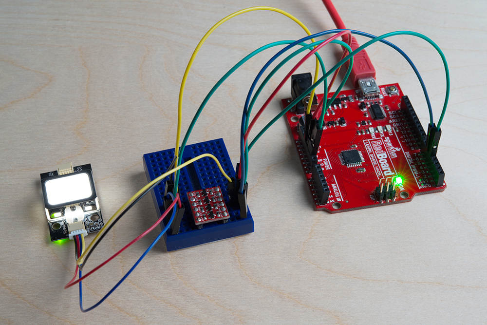
After wiring the circuit, it should look like this:
Option 2: Voltage Division w/ 3x 10kOhm Resistors
Otherwise, you could use 3x 10kOhm resistors to divide the voltage from a 5V Arduino down to 3.3V for the fingerprint scanner (FPS) similar to the "Uni-Directional" application circuit on our old logic level converter as shown below:

Below is the connection between the FPS, 5V Arduino, and resistors for voltage division:
| Voltage Divider | Fingerprint Scanner(Pin #) | Voltage Divider | 5V Arduino w/ Atmega328P |
|---|---|---|---|
| UART_TX (3.3V TTL) (Pin 1) | RX (pin 4) | ||
| GND < 10kOhm > 10kOhm |
UART_RX (3.3V TTL) (Pin 2) | 10kOhm | TX (pin 5) |
| GND | GND (Pin 3) | GND | GND |
| Vin (3.3V~6V) (Pin 4) | 5V |
Note: You can add the two 10kOhm resistors in series for 20kOhms.
After wiring the circuit up, it should look like this:

Using Demo Software w/ a FTDI
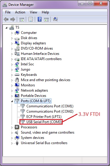
After making your connection with the 3.3V FTDI, connect the USB cable to your computer. Assuming that the FTDI drivers have been installed, make note of what COM port on which the FTDI enumerated. On a Windows computer, I was able to view it in the device manager as shown below:
Opening and Connecting to the SDK_Demo.exe
For basic operation with the demo software, it is recommended to download the demo software development kit (SDK) that is linked in product page's documents section. Each demo software is unique to that version of the scanner and it might not work with the other models.
To use the demo SDK on a computer:
- Download the SDK_DEMO.exe from the product page under the "Documents" tab.
- Unzip the folder.
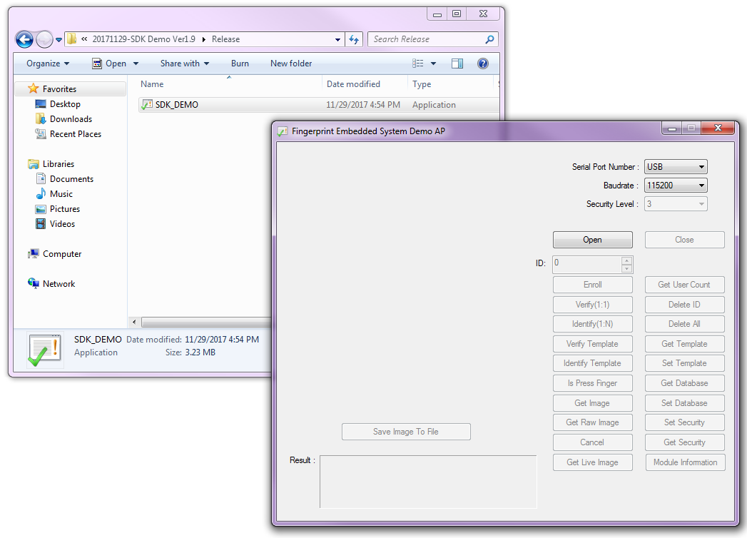
- Go to the directory that it was unzipped, which should look similar to this: ...\20171129-SDK Demo Ver1.9\Release .
- Open the SDK_DEMO.exe executable.
- Select the COM port that the FTDI enumerated to in the Serial Port Number's drop down menu.*
- Select 9600 in the Baudrate's drop down menu.
- Click on the Open button.
*Note: The available COM ports range from "COM3" to "COM10". If your USB-to-serial converter enumerates to a number higher than that, you would need to go to your computer's device manager to force it to a lower COM port number.
The image below shows how the SDK_DEMO.exe looks like before connecting:
Once the demo SDK has been opened, it will look like this:
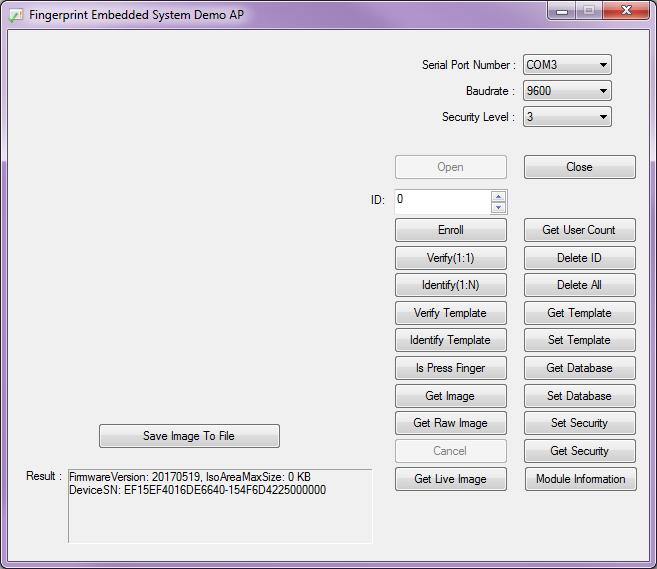
The FirmwareVersion and DeviceSN might be different depending the serial number that the manufacturer assigned. After connecting the fingerprint scanner to the FTDI, I was able to utilize all of the features as stated in the datasheet. The features in the demo software are based on the protocol commands. We will go over two features that are frequently used in this section. If you are interested, feel free to experiment and test the other features.
Enrolling
To enroll a fingerprint to the module, you would need to enroll your finger three times for each ID before the scanner can save it as a template. The white LED will light up to begin reading your fingerprint:
To enroll a fingerprint:
- Select an ID that has no fingerprint template stored by adjusting the number in the ID: field. For this example, we will assume that there is nothing in template "0" .
- Press the Enroll button. The SDK_Demo.exe will respond in the Result: output by requesting "to input finger1!"
- Place a finger on the FPS. The output will state that it is "Processing Fingerprint..."
- Remove your finger when it asks for "to input finger2!"
- Place and remove your finger until the FPS has successfully read your fingerprint 3x.
- A notification will be provided when you have enrolled your fingerprint successfully. For template 0, it will respond by saying: "Enroll Ok (ID=0)!" At this point, the fingerprint scanner's white LED will turn off.
If the scanner is not able to recognize a unique fingerprint or detect the finger that was placed on the scanner, it will stop the enrollment and respond with a "timeout!" . If the scanner is not able to recognize the fingerprint at anytime during the enrollment, you will receive a response: "The enrollment is failed!" Make sure that there is sufficient contact with the scanner and that the finger is placed in the same position during enrollment.
The template will have a number associated with the fingerprint scanner and it will be saved in its local database.
Identifying
After enrolling, you will want to test to see if the fingerprint can be identified. To test and verify, press on the Identify(1:N). The white LED will being to light up and a request to "Input finger!" The SDK_DEMO.exe will check through the local database to see if it can recognize fingerprint against the saved fingerprint templates. If successful, it will respond with an ID that matches and the time it took to identify: "ID=0: 546ms;" .
Example Code for Arduino
Using SDK_Demo.exe w/ FPS_Serial_Passthrough.ino
Testing this with a Arduino Uno based microcontroller (i.e RedBoard Programmed w/ Arduino or Arduino Uno ) and the serial passthrough code, I was able to connect to the SDK demo software provided on the fingerprint scanner's product page. This might be another alternative if you do not have a 3.3V FTDI to connect to your fingerprint scanner.
To use the SDK demo with an Arduino microcontroller connected to the fingerprint scanner, you need to:
- Build a circuit between the Arduino and scanner using logic level translation. This is assuming that you are using a 5V Arduino.
- In the Arduion IDE, upload the FPS_Serial_Passthrough.ino sketch to your Arduino.
- In the SDK_demo.exe labeled Serial Port Number , select a COM port that is lower than COM10 (COM3 should be the lowest that you can use).
- Select a baud rate of 9600 .
- After uploading the serial passthrough code or powering the Arduino for the first time during the session, you will need to reset the Arduino. Press the RESET button.
- After the Arduino initializes, press on the "Open" button in the SDK
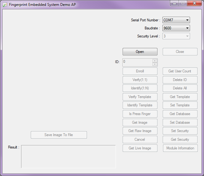
The image below shows the SDK_Demo before it is opened with an Arduino on COM7 and a baud of 9600 :
Hawley's FPS_GT511C3 Library for Arduino
Note: This example assumes you are using the latest version of the Arduino IDE on your desktop. If this is your first time using Arduino, please review our tutorial on installing the Arduino IDE. If you have not previously installed an Arduino library, please check out our installation guide.
To create a standalone system that can read fingerprints without the aid of a computer, you will need to replicate what the demo software does in Arduino code. Luckily there is a fingerprint scanner Arduino library written by jhawley. The code does most of the leg work for you and handles a lot of the complicated protocol commands. You can download it directly using the link below or find the source files on the GitHub repo.
This library is limited in functionality compared to the SDK_Demo.exe, but it gets the job done. If you look at the comments in the FPS_GT511C3's library, certain functions were not implemented due to the Atmega328P's memory restrictions. Certain functions were also not needed when it was originally written. The FPS_GT511C3 library and example code works with the GT511C3 and GT511C1R models.
The library has three examples. Each one performs a different task with the FPS:
- Blink the white LED.
- Enroll a fingerprint.
- Attempt to identify the fingerprint against the local database.
Example 1: Basic Serial Test w/ FPS_Blink.ino
The FPS_Blink.ino sketch is a basic test to see if the Arduino is able to talk with the fingerprint scanner through the serial UART. As a basic sanity check, it is recommended to test this code to make sure that your connections are correct and the scanner is able to send/receive commands. The code sets up a the Arduino's hardware serial UART for debugging and tells the scanner to send serial debug messages. The code also initializes the connection with the fingerprint scanner.
Once the setup is complete, the Arduino will tell the fingerprint scanner to toggle the white LED. By opening the serial monitor at 9600 baud, you should see this output:
FPS - Open
FPS - SEND: "55 AA 01 00 00 00 00 00 01 00 01 01"
FPS - RECV: "55 AA 01 00 00 00 00 00 30 00 30 01"

FPS - LED on
FPS - SEND: "55 AA 01 00 01 00 00 00 12 00 13 01"
FPS - RECV: "55 AA 01 00 00 00 00 00 30 00 30 01"

FPS - LED off
FPS - SEND: "55 AA 01 00 00 00 00 00 12 00 12 01"
FPS - RECV: "55 AA 01 00 00 00 00 00 30 00 30 01"
The code will repeat and toggle the LED while printing to the serial monitor.
Example 2: Enrolling w/ FPS_Enroll.ino
The FPS_Enroll.ino is used for enrolling a fingerprint each time the Arduino is reset. The fingerprint will save in a template within the scanner's local database. The code will initialize like the FPS_Blink.ino sketch. Instead of toggling the LED, the LED will remain on to scan a fingerprint. Before the end of the setup() function, it will jump to the Enroll() function. The Enroll() function will look for an empty template ID and begin enrolling your fingerprint.
Below is what to expect in the serial monitor when enrolling a finger successfully:
    Press finger to Enroll #3
    Remove finger
    Press same finger again
    Remove finger
    Press same finger yet again
    Remove finger
    Enrolling Successful
The scanner will reject a fingerprint if the scanner is not able to recognize your finger at anytime during the enrollment process. If your finger is not placed in the same position like the other scans, the template will not be saved. When this happens, you will need to restart the enrollment process.
Below is what to expect when the scanner fails if the first scan does not match the second scan.
    Press finger to Enroll #4
    Remove finger
    Press same finger again
    Failed to capture second finger
Try enrolling a fingerprint by uploading the code and following the serial monitor's output. To enroll more than one fingerprint, just reset the Arduino.
Example 3: Identifying w/ FPS_IDFinger.ino
The FPS_IDFinger.ino sketch checks to see if a finger is on the scanner. Once a finger has been placed on the scanner, it checks the fingerprint against any of the fingerprints saved in the local database. You will be notified through the serial monitor if the fingerprint matches an ID, if the fingerprint is not found, or when it fails to read the fingerprint. After checking and lifting your finger, it will request for another fingerprint to check.
Below is what you would expect when using this example:
Verified ID:0
Finger not found
Finger not found
Verified ID:0
Verified ID:0
Please press finger
Please press finger
Please press finger
Verified ID:2
Please press finger
Verified ID:2
Please press finger
Looking at the output, "Finger not found" usually means that: the fingerprint does not match any of the template IDs or when the the scanner is not able to clearly read the fingerprint. If the finger has been enrolled, you would need to make sure that you place the fingerprint on the scanner just like when you scanned the finger.
Adjust Code for GT-521F52's 3000 ID's
Depending on what model you are using, make sure to change number of fingerprint IDs. For example,the GT521F52 can hold 3000 fingerprint IDs instead of 200. When enrolling a fingerprint to the GT-521F52, you will need to make sure to change retval < 200 to retval < 3000 for the FPS_GT511C3::Enroll1(), FPS_GT511C3::Enroll2(), and FPS_GT511C3::Enroll3() functions in the FPS_GT511C3.cpp file.
When identifying a fingerprint with the GT-521F52, make sure to update if (retval > 200) retval = 200; to if (retval > 3000) retval = 3000; for the FPS_GT511C3::Identify1_N() function in the FPS_GT511C3.cpp file. You will also need change id <200 to id <3000 in the FPS_IDFinger.ino file.
Try testing the scanner with the code to see if the scanner is able to read the fingerprints that were enrolled.
Software Serial w/ Other Microcontrollers
The demo code was originally designed for the ATmega328P on the Arduino Uno. If you were using it with ATmega2560 (i.e. Arduino Mega 2560) or ATmega32U4 (i.e. Arduino Leonardo, Pro Micro 5V/16MHz, Pro Micro 3.3V/8Mhz, FioV3, etc.), you would need to re-configure the software serial pin definitions and adjust the connections. Not all the pins can support change interrupts for a serial Rx pin depending on what Arduino microcontroller is used. For more information, try looking at the reference language for the Software Serial library.
To use the FPS on an Arduino Mega 2560 or Arduino Leonardo, you would just need to comment out the line where it says:
language:c
SoftwareSerial fps(4, 5); // (Arduino SS_RX = pin 4, Arduino SS_TX = pin 5)
and uncomment out the line here:
language:c
SoftwareSerial fps(10, 11); // (Arduino SS_RX = pin 10, Arduino SS_TX = pin 11)
Once you change the code, make sure to rewire your connections to follow the pin definitions.
Caution: The FPS_GT511C3 library may not work for all microcontrollers using the Arduino IDE. As you move away from the ATmega328P family, you may need to modify the code or port the library over to get it working. It would be easier and faster to just have an Atmega328P bootloaded with Arduino to handle the FPS code. To use the fingerprint scanner, you could just write additional code to have the ATmega328P send serial data to the other microcontroller.
Firmware Overview
If you are interested, this section goes just a little further by looking briefly at the command protocol. We will be taking a quick look at the fingerprint scanner's blink example with an Arduino and how the command protocol functions based on the manual.
Verifying the Checksum Value
To verify the check sum for the command packet (command) or response packet (acknowledge), you would add the bytes of the command start codes, device id, parameter, and command/response. Looking at the Arduino blink example, the serial monitor outputs:
FPS - Open
FPS - SEND: "55 AA 01 00 00 00 00 00 01 00 01 01"
FPS - RECV: "55 AA 01 00 00 00 00 00 30 00 30 01"

FPS - LED on
FPS - SEND: "55 AA 01 00 01 00 00 00 12 00 13 01"
FPS - RECV: "55 AA 01 00 00 00 00 00 30 00 30 01"

FPS - LED off
FPS - SEND: "55 AA 01 00 00 00 00 00 12 00 12 01"
FPS - RECV: "55 AA 01 00 00 00 00 00 30 00 30 01"
The example displays the packet structure as a multi-byte item represented as little endian. Breaking down the LED command to turn the LED OFF in hex, it is:
55 AA 01 00 00 00 00 00 12 00 12 01
, where Command Start code1 = 0x55
        Command Start code2 = 0xAA
        Device ID = 0x00 01
        Input parameter = 0x00 00 00 00
        Command Code = 0x00 12
By adding the hex values with a programmer's calculator as stated in the datasheet:
OFFSET[0] + OFFSET[1] + OFFSET[2] + OFFSET[3] + OFFSET[4] + OFFSET[5] + OFFSET[6] + OFFSET[7] + OFFSET[8] + OFFSET[9] = 0x55 +0xAA + 0x01 + 0x00 + 0x00 + 0x00 + 0x00 + 0x00 + 0x12 + 0x00
, we are able to get the same output result as the command packet's check sum:
Checksum = 0x01 12
Since the check sum is read as little endian, the output reads the checksum as "12 01".
FPS Experiments
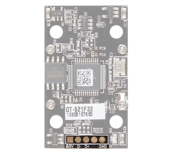
Underneath the enclosure, the scanner uses LEDs and tiny camera to read a fingerprint. On the back, there is a processor that will try to read whatever is placed on top of the scanner's enclosure.
Hand Drawn "Fingerprint"
I was interested in seeing if the fingerprint scanner was able to identify any other items placed on the fingerprint scanner. I tested using a few drawings on a sticky note:
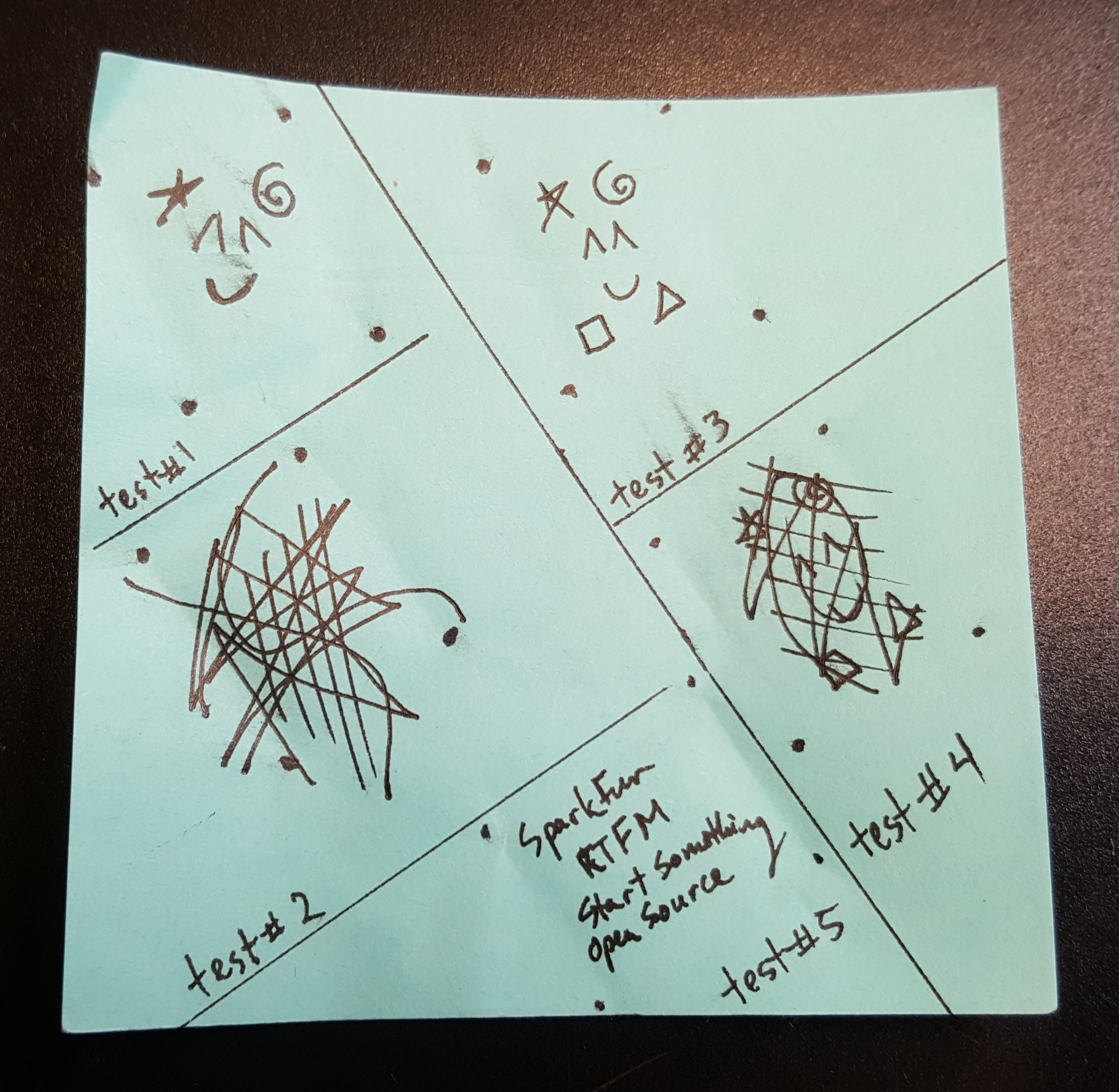
I drew fiducials to align the fingerprint scanner's with the drawing in the image below. This ensured that the fingerprint was placed in the same position for each scan.
I first drew a pattern in test #1 and test #2 . Test #1 failed to enroll properly, since it did not have a lot of details. I continued to test the drawing in test #1 to see when the scanner would accept the drawing. Test #2 was successful in enrolling and identifying by adding a little bit more detail. In test #3, I drew a bit more, but the fingerprint scanner was unable to recognize the drawing. The drawing in test #4 was enough for the scanner to recognize by adding lines and scribbles similar to the unique patterns of a person's fingerprint. In test #5, I was interested in seeing if the scanner was able to recognize words as a fingerprint. While the fingerprint scanner was able to recognize that there was a "finger" pressed on the scanner, it failed to complete the enrollment process. The words probably did not create enough of a pattern for the scanner to accept.
I was also interested in how each of the images would look like after it was scanned. Luckily, the SDK_Demo.exe had a feature to get the image and save as a bitmap. The "Get Image" button requires a valid fingerprint press before the device begins scanning. The "Get Raw Image" immediately scans whatever is on the scanner even if it is not a valid fingerprint pattern. After clicking on the "Save Image To File", a 240x216 sized bitmap image was taken from the GT-511C1R's optical sensing area and saved to my computer. Below are images of the tests after saving the patterns:
| Test #1 (FAIL) | Test #2 (PASS) | Test #3 (FAIL) | Test #4 (PASS) | Test #5 (FAIL) |
|---|---|---|---|---|

|

|

|

|

|
More Failed Attempts
I tried using the silkscreen and traces of the SparkFun EL Sequencer to see if the scanner was able to enroll. Unfortunately, it was not able to accept the board as a fingerprint. The board seem to be too far away causing the image to be dimly lit and the silkscreen was not sufficient enough to pass as a pattern. Below is an image taken of one of the SparkFun EL Sequencer's silkscreen that failed to enroll:

As a final test, scanner was used with the palm of a hand. While it was able to enroll once, the scanner was not able to recognize it a majority of the time. It was not easy to place the fingerprint scanner on the same location of the palm. The scanner was only able to recognize the palm once. It's possible that the ridges on the palm of a hand and the amount of pressure that was placed on the scanner was not sufficient to enough.
Troubleshooting
Listed below are frequently asked questions and tech support tips on troubleshooting common issues related to the fingerprint scanner.
1.) I am not sure if the fingerprint scanner is responding to any of the commands with my Arduino. What can I do?
Make sure that there are no loose connections. If you are using the JST SH jumper 4 wire assembly, the cable's wire is relatively thin compared to the Arduino's socket. A small bump can break the connection requiring you to power cycle the fingerprint scanner or reset the Arduino.
Also, make sure that you are connecting the fingerprint scanner to your microcontroller correctly based on the Arduino model and defined software serial pins.
2.) Scanner not recognizing your fingers when enrolling?
There can be issues trying to enroll when using the SDK_Demo.exe or Arduino example code. This is usually due to fingers being dry and not having good contact on the scanner. The finger has to have the same pressure applied and be placed in the same position for all three enrollments. The timing of your finger on the scanner is a little tricky too. A tech support representative had to try a few times before it was able to enroll a finger. This is common with any fingerprint scanner like the one that is on a smartphone.
If you see these errors, you probably did not place your finger on the fingerprint scanner sufficiently for each enrollment:
Bad finger!
or
Failed to capture second finger
or
The enrollment is failed!
If you are using an FTDI, try to follow the directions for enrolling with a FTDI again. You may need to close out the program and unplugging/replugging the FTDI before re-enrolling. If you are using an Arduino, try the enrollment process again by placing your finger on the scanner, resetting the Arduino, and following the directions in the serial monitor.
3.) Scanner not recognizing your fingers when verifying?
If you are trying to verify a fingerprint, make sure to place the finger on the scanner just like when it was enrolled. The same conditions for scanning a fingerprint apply as explained above for enrolling.
4.) Will the GT-521F32 / GT-521F52 fingerprint scanner work with the FPS_GT511C3 library?
Yes, it will. It has been tested. Each of the fingerprint scanners use the same command protocols so the Arduino example code can be used for any of the scanners. However, the library will not be compatible if you using a different scanner that is not manufactured by ADH-Tech.
5.) Can I use an Arduino Due?
Unfortunately, the fingerprint scanner's Arduino example code for the does not work with the Arduino Due. You would need to modify the code and use it with the hardware serial UARTs because the Arduino Due does not support software serial. This old forum post will explain why there are compilation errors with the example code using the Arduino Due board definition => Arduino.cc Forums: SoftwareSerial for Arduino Due.
6.) What are the dimensions of the fingerprint scanner?
The dimensions are listed on page 8 of the datasheet.
7.) I soldered to the back of the fingerprint scanner and none of the Arduino examples work.
Those pins are broken out if you wanted to connect the fingerprint scanner directly to a USB port. The USB data lines are different from a serial UART protocol. If you are using the Arduino examples for your project, it is recommended to connect to the JST SH connector. If you are interested in plugging the scanner directly to your computer's COM port, feel free to test it out and experiment. It has been tested to work with the previous models.
Fingerprint Scanner USB Pinout
Surprise! You found the extra section on how to connect to the USB pins! The connection to the USB was not included in the beginning of the tutorial because the main objective was to use it in an embedded project with an Arduino microcontroller. To connect the fingerprint scanner with the demo software and your computer's USB port, you can connect the pads on the back of the board labeled J1 directly to the USB port of your computer. The image and table below shows the pinout:
| Fingerprint Scanner | USB Port |
|---|---|
| Shield (right most pin) | USB Shield (not necessary if using a USB breakout board). Tied to GND. |
| GND | GND (Standard USB Black Wire) |
| D+ | D+ (Standard USB White Wire) |
| D- | D- (Standard USB Green Wire) |
| Vcc (square pad) | 5V (Standard USB Red Wire) |
For more information about soldering to the USB pads, check out the instructions provided in the the older tutorial. The directions are essentially the same.
Resources and Going Further
Now that you've successfully got your fingerprint scanner up and running, it's time to incorporate it into your own project!
For more information, check out the resources below :
- GT-521F32/GT-521F52
- GitHub Repository for the FPS's Arduino Example Code
- SparkFun Product Showcase: GT-521Fx2 Fingerprint Scanner
More Tutorials and Project Examples!
For more tutorials and project ideas using the older models of ADH-Tech's fingerprint scanner, check below. Most of the examples listed below use the older module but you should not notice any significant differences in funcionality between the models.
Arduino
- Instructables.com - DIY Fingerprint Scanning Garage Door Opener
- Hackaday: Biometric Secured Goflcart Allows for Keylesss Start
- GitHub: GT5X Arduino Library
- Starting Electronics - GT-511C3 Fingerprint Scanner Hardware, Wiring and Connector Numbering
- Homautomation - Playing with finger print scanner (FPS) on arduino
- SparkFun's Fellowship of the Things! - Internet of Things Ep 1: AirLock Demo Project w/ 3 Factor Authentication and GitHub Repo for IoT 3 Factor Verification
Raspberry Pi
There’s a Raspberry Pi Python Library for this fingerprint scanner if you look at the post by user jeanmachuca in the Pi forums.
There appears to be an article that uses the GT-511C1R with a Raspberry Pi as a server and SQLite [ FingerScanner: Embedding a Fingerprint Scanner in a Raspberry Pi ]. Based on this information, it’s possible to have remote management of a database on multiple fingerprint scanners from one server.
Node.js
There’s an example in Node.js with an API in the-AjK's GitHub repository.
BeagleBone Black
There's a BeagleBone Black Python Library by user JamesMarcogliese_'s capstone design team.
.NET
Or check out Unosquare's .NET implementation on GitHub.