Exploring XBees and XCTU
Selecting an Explorer
- VREF - VREF (pin 14) on the XBee Series 1 is not supported by the XBee 3 hardware. As indicated in the hardware reference manual, you should not connect to this pin on boards labeled with VREF.
- Brownout - If your XBee 3 experiences any voltage brownouts or supply dips when powering up, your XBee may not start up as expected. The hardware reference manual indicates that:
Parts with an early revision of the microcontroller unit (MCU) may experience an issue recovering from brownouts under rare conditions.
To remedy the issue, you must power cycle the XBee Series 3 module. One method is to remove the XBee while the board is powered. Then reinsert the module back carefully into the sockets. Otherwise, you can perform a hardware reset by toggling the XBee 3's reset pin. To automate this, during startup, you can solder a wire between the reset pin and the 3.3V I/O pin of a microcontroller Toggling the reset pin with a minimum of 50ns-100ns will reset the XBee Series 3. As an example, check out this Arduino example code for the XBee Series 3 on the wireless joystick.
For more detailed information regarding the differences, check out the XBee 3 Documentation.
The first step to communicating with your XBee is picking an interface board that allows you to. XBee Explorers act as a gateway between your computer and your XBee. There are a few to pick from, each offering their own, key differences. Here's a quick overview of each:
XBee Explorer USB
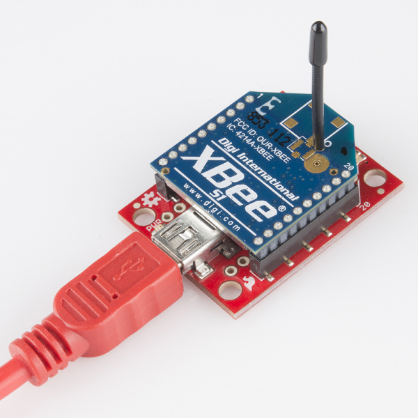
The XBee Explorer USB is the most popular of the Explorers. It's equipped with a mini-B USB connector, so you'll need the proper USB cable to connect it to your computer.
The highlight of this board is an FT231X USB-to-Serial converter. That's what translates data between your computer and the XBee. There's also a reset button, and a voltage regulator to supply the XBee with plenty of power. In addition, there are four LEDs that'll help if you ever need to debug your XBee: RX, TX, RSSI (signal-strength indicator), and a power indicator.
This board also breaks out each of the XBee's I/O pins to a pair of breadboard-compatible headers. So if you want to make use of the XBee's extended functionality, you can solder some header pins into those, or even just solder some wire.
XBee Explorer USB Dongle
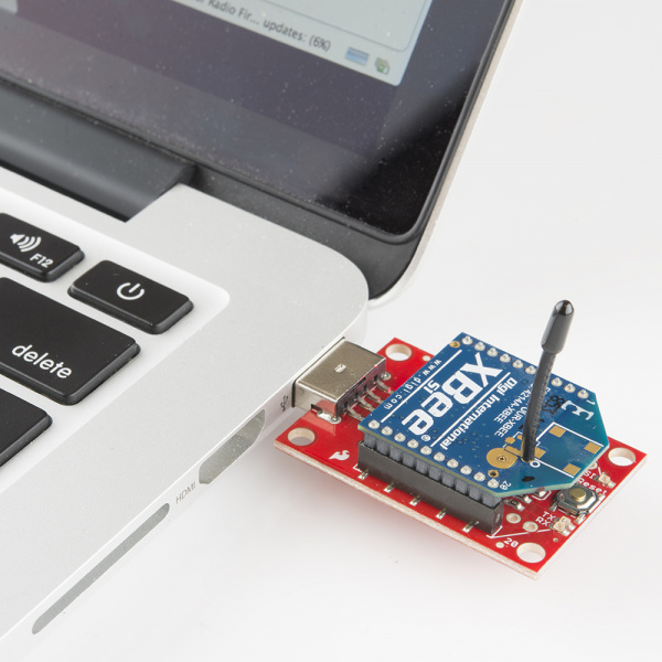
The XBee Explorer Dongle is an extension of the Explorer. In fact, the only real difference between this and its predecessor is the USB connector. The Dongle can be connected directly to your laptop or PC USB port.
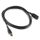
Or, if you need some distance from your computer, you can use a USB extension cable.
USB Cable Extension - 6 Foot
CAB-00517The Dongle still shares all of the features of its sibling -- reset button, LEDs, voltage regulator, and breadboard-compatible pin breakouts.
XBee Explorer Serial
Computers with an RS-232 serial port are becoming harder and harder to find, but if you do have one of those relics, the XBee Explorer Serial is a viable option.
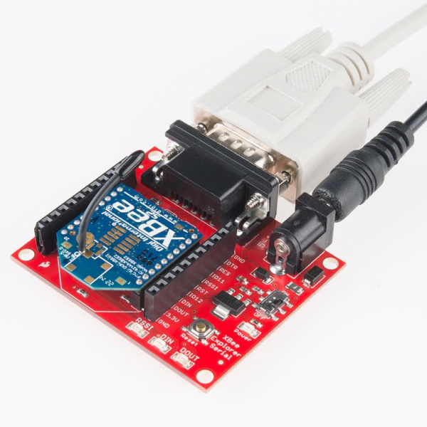
The Serial Explorer has a bigger footprint than its USB-based brethren, but still shares most of the same features. There are RX and TX LEDs, reset button, break-out pins, and a voltage regulator. One additional feature that the Serial Explorer has is an On/Off switch on board. This enables the user to turn on or off the power supply to the XBee module.
One additional feature available on the Serial Explorer are two jumpers available near the DB9 connector. These allow the user to swap the configuration of the DB9 connector to work with either a straight through cable (DCE configuration), or a switched cable (DTE configuration). If you’re using our Serial Cable, the default DCE configuration of the jumpers is fine.
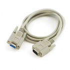
Serial Cable DE9 M/F - 6 Foot
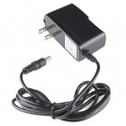
CAB-00065The Serial Explorer does require an external power supply. It has a barrel jack connector which will work with our 12V, 9V, or 5V wall adapters. Make sure the selected power supply can source enough current for the XBee you are using.
