ESP8266 WiFi Shield Hookup Guide
(Re-)Programming the ESP8266
The ESP8266 works great and it's cheap, but it can be so much more than a simple AT-command-driven serial-to-WiFi gateway! It can be reprogrammed just like any microcontroller, and you can even load Arduino sketches onto it.
Danger zone! Uploading new code to the ESP8266 will overwrite the AT command firmware it ships with. You can always put that firmware back on, but the AT library probably won't work with whatever custom code you load onto the ESP8266.
This section is included with this tutorial, in case anyone wants to use the ESP8266 WiFi Shield as more of a general purpose ESP8266 development board. You can skip it if you intend on using the Shield as an actual Arduino Shield.
Programming Hardware
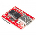
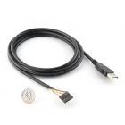
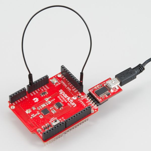
To load code onto the ESP8266 WiFi Shield, you'll need a couple extra bits of hardware: a 5V FTDI Basic and a wire.
Actually, any device that can translate computer-speak (either USB or RS-232) to TTL serial could work (see the old RS232 Shifter), but the FTDI Basic and it's FTDI Cable counterpart work best, as they mate directly with the ESP8266 WiFi Shield's programming header.
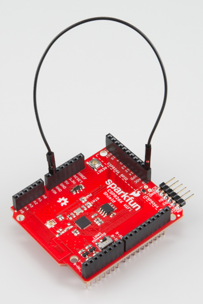
You'll also need a jumper wire to easily connect and disconnect GPIO0 from GND. GPIO0 controls the ESP8266's run mode -- if it's LOW (0V, GND) when the chip boots up, it starts up its bootloader. If GPIO0 is high on bootup, it'll begin running its application code.
| GPIO0 Value | ESP8266 Mode |
|---|---|
| HIGH (3.3V) | Run Program |
| LOW (0V) | Bootloader |
There is a pull-up resistor attached to GPIO0, so all you should need to do is pull it to GND when uploading code and leave it floating otherwise. There are a variety of ways to achieve this connection, the easiest of which may be running a male-to-male jumper wire between female headers.
If you're going to be doing a lot of code uploads, perhaps you'll want to set up a switch between GND and floating.
Installing the Addon With the Arduino Boards Manager
With the release of Arduino 1.6.4, adding third party boards to the Arduino IDE is easily achieved through the new board manager. If you're running an older version of Arduino (1.6.3 or earlier), we recommend upgrading now. As always, you can download the latest version of Arduino from arduino.cc.
This ESP8266 addon for Arduino is based on the amazing work by Ivan Grokhotkov and the rest of the ESP8266 community. Check out the ESP8266 Arduino GitHub repository for more information.
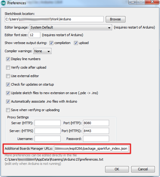
To begin, we'll need to update the board manager with a custom URL. Open up Arduino, then go to the Preferences (File > Preferences). Then, towards the bottom of the window, copy this URL into the "Additional Board Manager URLs" text box:
https://raw.githubusercontent.com/sparkfun/Arduino_Boards/master/IDE_Board_Manager/package_sparkfun_index.json
If you already have a URL in there, and want to keep it, you can separate multiple URLs by placing a comma between them.
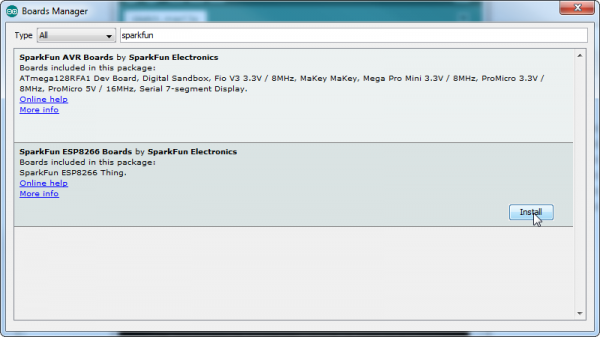
Hit OK. Then navigate to the Board Manager by going to Tools > Boards > Boards Manager. There should be a couple new entries in addition to the standard Arduino boards. Look for SparkFun ESP8266 Development Boards. Click on that entry, then select Install.
The board definitions and tools for the ESP8266 Thing include a whole new set of gcc, g++, and other reasonably large, compiled binaries, so it may take a few minutes to download and install (the archived file is ~110MB). Once the installation has completed, an Arduino-blue "INSTALLED" will appear next to the entry.
Selecting the ESP8266 Board
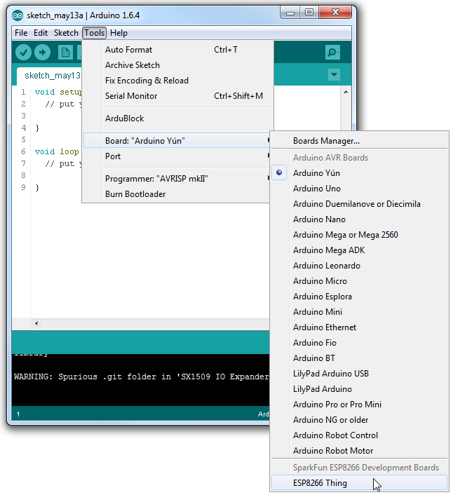
With the Board addon installed, all that's left to do is select the proper board from the Tools > Boards menu. Under that menu, find "SparkFun ESP8266 Thing" and select that.
Then select your FTDI's port number under the Tools > Port menu.
Uploading and Running a Sketch
Now that you've got the environment set up, it's time to upload some code. If you're using an FTDI Basic to upload code, you can also use that board to power the WiFi Shield. Remove the Shield from your Arduino, plug in the FTDI cable, and the power LED should illuminate.
Load up a simple blink sketch -- setting the blink pin to 5 (attached to the Shield's STAT LED).
language:c
#define ESP8266_LED 5

void setup()
{
  pinMode(ESP8266_LED, OUTPUT);
}

void loop()
{
  digitalWrite(ESP8266_LED, HIGH);
  delay(500);
  digitalWrite(ESP8266_LED, LOW);
  delay(500);
}
Don't forget, when you upload a sketch to the ESP8266, to make sure GPIO0 is connected to GND. Viola! You're on your way to being an ESP8266 developer! For more guidance on ESP8266 development, check out our ESP8266 Thing Hookup Guide, notably the sections starting around the example sketches.
