ESP8266 WiFi Shield Hookup Guide
 jimblom
Hardware Overview
This section covers the hardware features of the ESP8266 WiFi Shield. Most of the board's action is on the top side, which should look a little something like this:
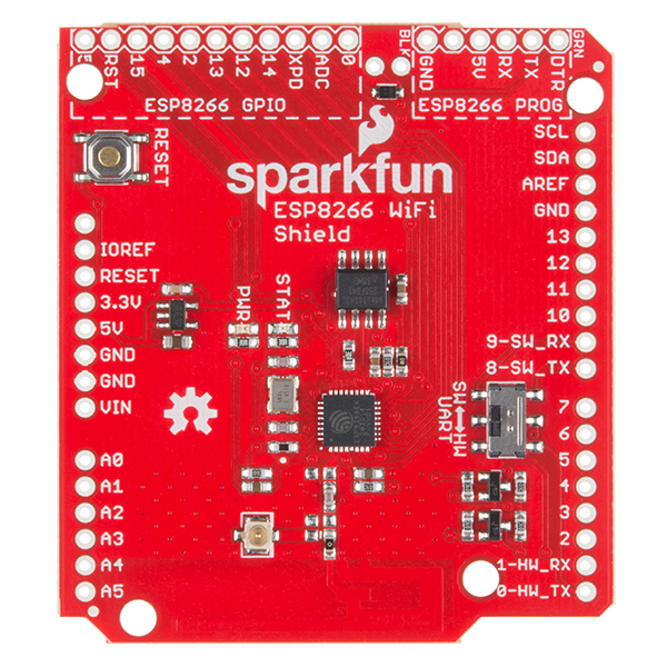
There are a couple features you should be familiar with, before equipping the Shield with headers and plopping it on you Arduino.
Serial Ports -- Selectable and Level Shifted
The ESP8266 WiFi Shield features selectable serial lines, which route the RX and TX signals to either the Arduino's devoted hardware serial port (on pins 0 and 1), or a software serial port on pins 8 and 9. The active port is selected by the on-board switch.
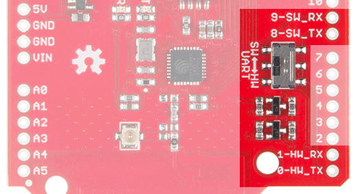
The switch's positions are labeled "SW" and "HW" for "software" and "hardware"; they should be intuitive -- slide towards the hardware port for "HW" and towards pins 8 and 9 for "SW".
The ESP8266's default baud rate is set to 9600, so, for most sketches, software serial works fine, and allows the hardware port to be used for debugging. We recommend keeping this switch set to "SW" unless you need those pins for something else, or just have to use hardware serial.
It's also important to note that the ESP8266's maximum input voltage is about 3.3V. To avoid any voltage conflict between a 5V Arduino and the ESP8266, the RX and TX signals are level shifted between 5V and 3.3V.
Arduino Reset Button
The shield's reset button is tied only to the Arduino. Pressing and releasing the button will restart the Arduino, running it's sketch from the top of the setup() function.
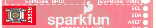
Pressing the reset button will have no immediate effect on the ESP8266.
LED Indicators
The WiFi Shield includes two LED indicators: a simple red power indicator and a blue "status" LED. The red power LED should illuminate whenever power is being delivered from the Arduino to the ESP8266 Shield. If you need to debug anything, checking for this LED should be your first step.
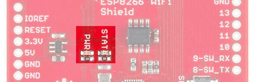
The blue status LED is tied into the firmware of the ESP8266. It'll blink, be solid, or turn off depending on which state it's in.
| LED State | ESP8266 State |
|---|---|
| Off | WiFi disconnected. Not configured. |
| Blinking | Station mode: ESP8266 attempting to connect to access point. AP mode: ESP8266 waiting for incoming connections |
| On | Station mode: ESP8266 connected to access point. AP mode: Devices connected to ESP8266 AP. |
The status LED is tied to GPIO 5 of the ESP8266.
ESP8266 GPIO and Programming Ports
The ESP8266 is a much more than a simple serial-to-WiFi gateway. It's has almost a dozen I/O that can be configured as digital inputs or outputs -- it even has a (relatively limited) ADC! These GPIO are all broken out towards the top-left side of the shield.
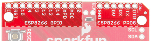
The shield's firmware is equipped with custom commands, which allow your Arduino to set, write, and read to these pins. More on that later.
The ESP8266 WiFi Shield can also be repurposed and reprogrammed through the programming port. Whether you want to add AT commands of your own, or flash custom firmware on the ESP8266, this port may come in very handy later on.
The pinout of the programming port matches our FTDI Basic breakouts. Solder on some male headers, and mate the two boards together to set up the programming interface. More on that later too!