Cellular Function Board - Blues Wireless Notecarrier
 El Duderino
 Introduction
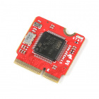
The SparkFun Cellular Function Board - Blues Wireless Notecarrier features the Notecard from Blues Wireless. The Notecard is unique among cellular modules as it has a built-in SIM card and includes a 10 year subscription and 500MB of data included in the price. The Notecard module also comes with integrated cellular, SIM, onboard GPS, 3-axis accelerometer with an on-chip temperature sensor. On top of that, the Notecard features outboard device firmware updates (DFU) meaning you can reprogram a connected Processor remotely through Blues' Notehub service! There are some limitations to this process so make sure to read further in this guide for more information on how to properly perform Outboard device firmware updates.
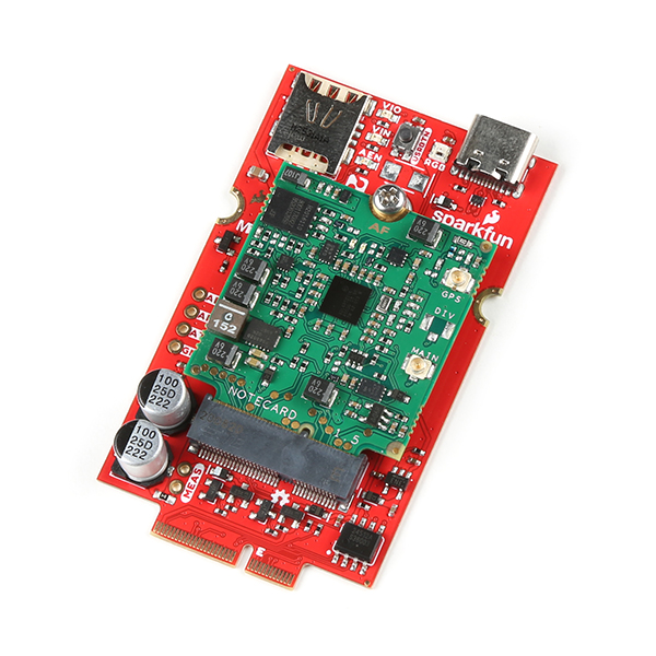
The MicroMod Cellular Function Board includes everything you need : a carrier board (Blues calls them Notecarriers) and the globally enabled NB-IoT & LTE-M M.2 based module (Blues calls them Notecards).
Required Materials
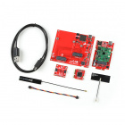
The following materials are necessary for following along with this guide (check out our all inclusive, starter kit). All Function Boards require a Main Board and Processor to connect to each other. Depending on your application, you may need a Single or Dual Main Board:
A Processor Board is needed to act as a host controller for the Function Board:
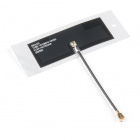
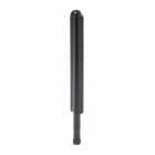
You'll also need a cellular and GNSS antenna:
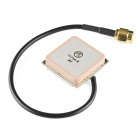
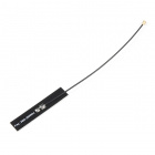
The Notecard Module uses u.Fl connectors for both antenna connections so, depending on your choice of antennas, you may also need an adapter cable like these:
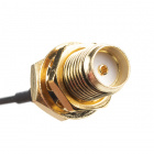
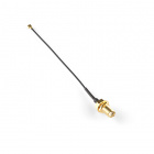
Interface Cable U.FL to SMA - 100mm
WRL-18154Suggested Reading
The MicroMod ecosystem is a unique way to allow users to customize their project to their needs. If you aren't familiar with the MicroMod system, click on the banner below for more information.
You may also want to go through the tutorials below if you are not familiar with the concepts covered in them:
Serial Peripheral Interface (SPI)
What is an Arduino?
Installing Arduino IDE
Getting Started with MicroMod
Hardware Overview
Let's take a closer look at the Notecard module and other hardware present on this Function Board.
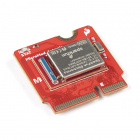
Blues Wireless Notecard - NOTE_NBGL-500
The Blues Wireless Notecard module offers a low-power cellular connection from a connected device to the cloud through either the Notehub service or alternate cellular service with a supported external SIM. The module has a built-in SIM card that includes a 10 year subscription and 500MB of data in the initial purchase price. The built-in SIM on the Notecard works in over 140 countries with varying levels of cellular coverage, for a complete list of compatible countries, refer to the Cellular Service section of the Notecard datasheet. The Cellular Function Board ships with the NOTE_NBGL-500 Notecard which operates over narrowband global networks (LTE-M, NB-IoT and GPRS).
The Notecard uses the BG95-M3 cellular module with integrated GNSS from Quectel. The GNSS supports GPS, GLONASS, BeiDou, Galileo and QZSS constellations. The Notecard also has an on-board 3-axis accelerometer with an on-chip temperature sensor. For a complete overview of the Notecard, refer to the datasheet.
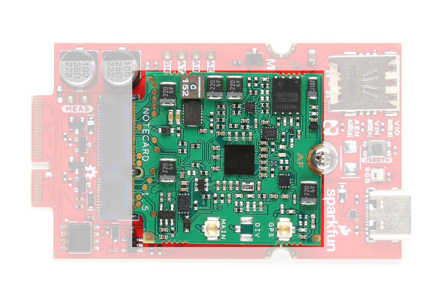
USB-C Connector
The USB-C connector provides a direct serial interface with the Notecard over a USB connection.
This connection allows you to use the Notecard with Blues Wireless' browser-based CLI, Notecard Playground. This CLI is very helpful for configuring and testing the Notecard quickly over USB. Those who prefer to download and use the CLI application locally can find it here.
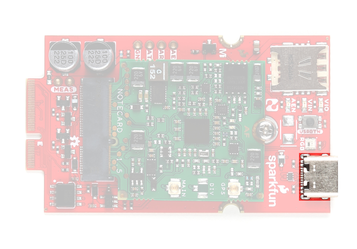
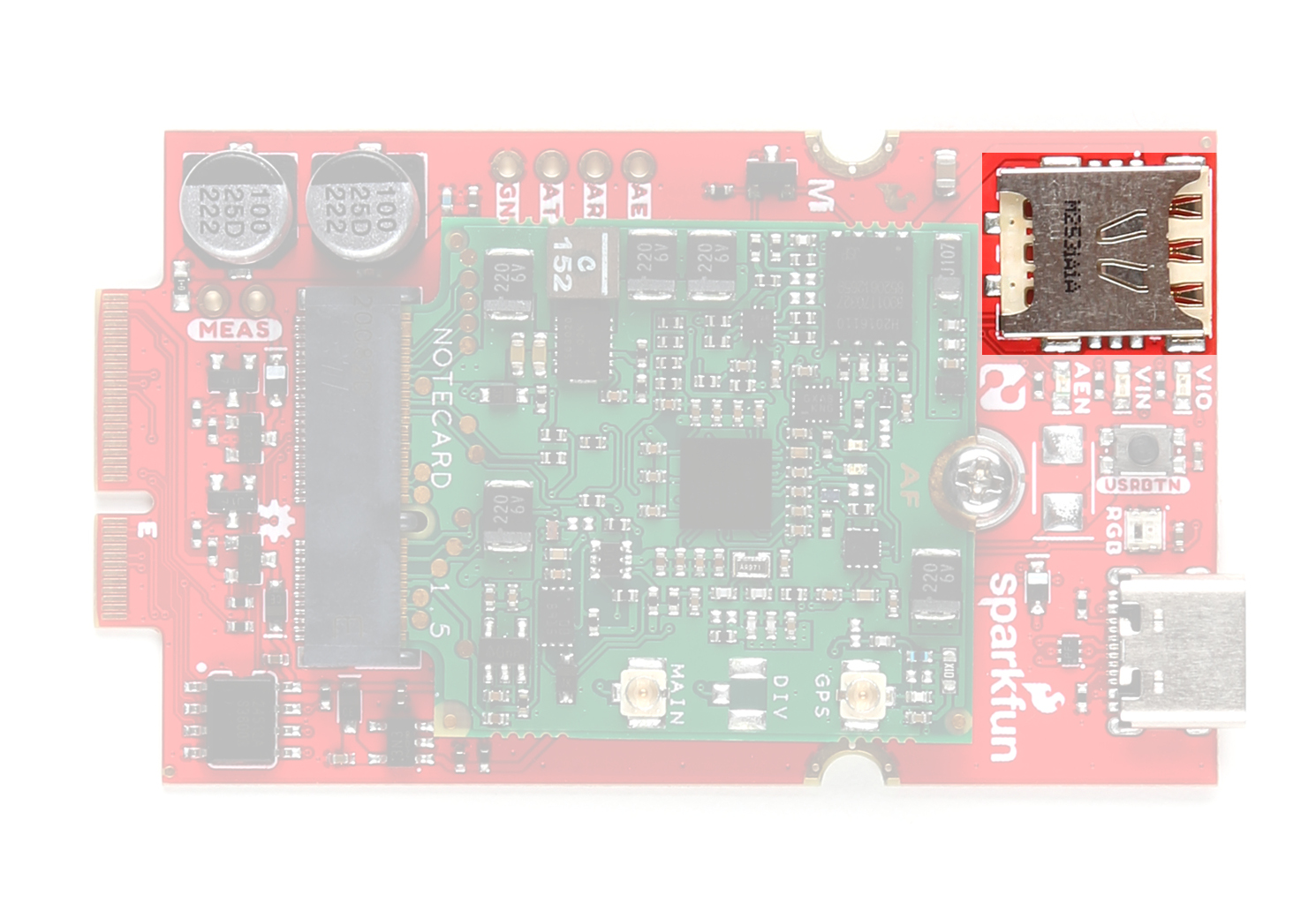
Nano-SIM Slot
The Function board includes a Nano-SIM slot for users who prefer to use their own nano SIM card instead of the built-in one on the Notecard module.
Enabling the external SIM capability requires updating several settings on the Notecard. Refer to this guide from Blues Wireless for detailed instructions for configuring the Notecard to work with an external SIM card. Reminder, this Function Board uses the NOTE_NBGL-500 Notecard so it only supports narrowband LTE networks (no 3G or 4G networks).
AUX UART PTH Header
The Function Board routes the auxiliary UART pins used for Outboard DFU on the Notecard to a 0.1"-spaced PTH header along with the Auxiliary Enable pin.

This interface allows for users to connect directly to the Notecard's auxiliary UART (AUX RX and AUX TX) as well as the Auxiliary Enable pin to toggle the auxiliary UART. The Function Board also routes the AUX1 to a pushbutton labeled "USRBTN" to allow for a user-configurable manual input on that pin.
LEDs
The board has three power indication LEDs labeled VIO, VIN, and AEN as well as a WS2812 RGB LED tied to the Notecard's AUX2 pin.
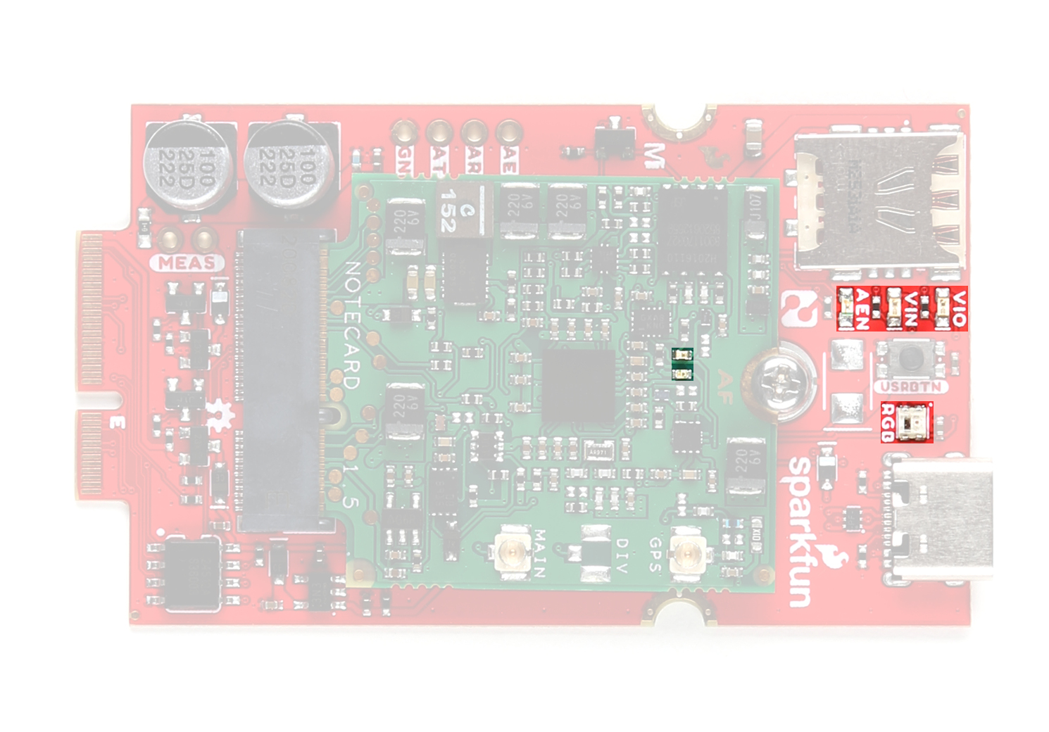
- VIO - 3.3V I/O voltage status. LED turns on when 3.3V from the MicroMod connector is present.
- VIN - Notecard power status. LED turns on when the Notecard is powered.
- AEN - Auxiliary UART status. LED turns on when the AEN pin is pulled HIGH to enable the auxiliary UART on the Notecard.
- RGB - AUX2 RGB LED. The data input for the WS2812 LED connects to AUX2 on the Notecard to allow for user-configured LED statuses. The data input also connects to F5 on the Function Board's MicroMod M.2 connector for users who prefer to manipulate the LED through a connected Processor.
The Notecard has two LEDs. The green LED reports modem activity and the red LED reports user activity.
Solder Jumpers
The Function Board has eight solder jumpers labeled: SHLD, VIO_LED, PWR_LED, AUX_EN_LED, RGB, ANT_PWR, WP, and MEAS
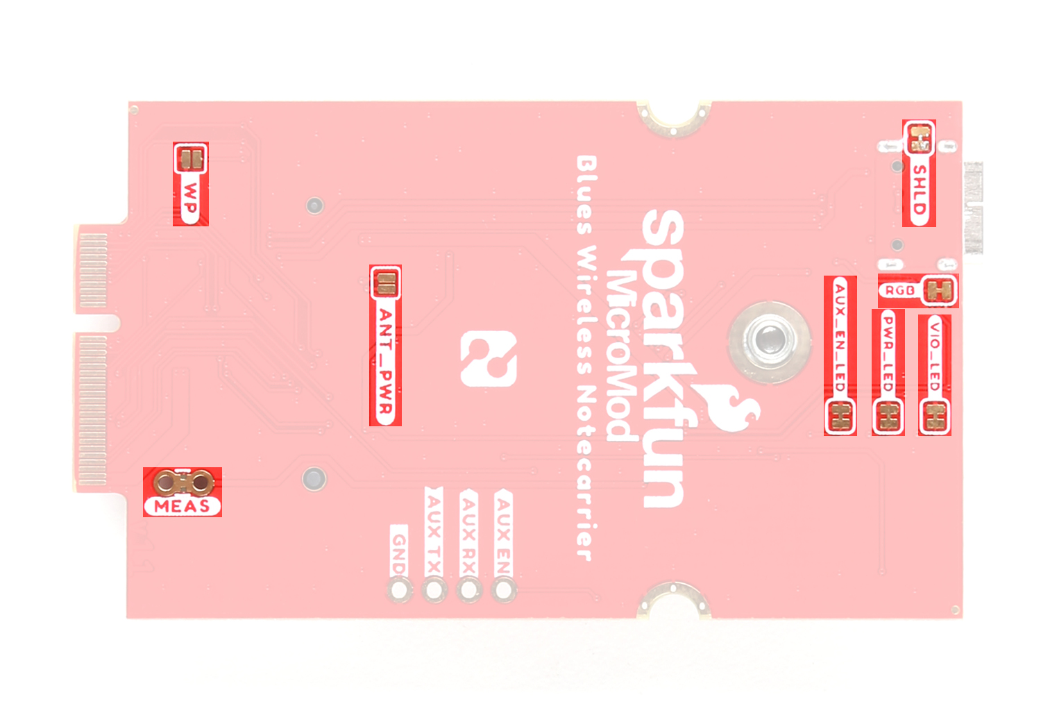
The table below outlines the jumpers labels, functions, default states and any notes regarding their behavior.
| Jumper Label | Default State | Function | Notes |
|---|---|---|---|
| SHLD | CLOSED | Connects USB-C Shield pin to Ground. | Manipulate this jumper to adjust whether or not the USB-C cable shield pin connects to the PCB's ground plane. |
| VIO_LED | CLOSED | Completes VIO status LED circuit. | Open to disable the labeled LED. |
| PWR_LED | CLOSED | Completes Notecard Power status LED circuit. | |
| AUX_EN_LED | CLOSED | Completes Auxiliary Enable status LED circuit. | |
| RGB | CLOSED | Completes the RGB LED circuit. | |
| ANT_PWR | OPEN | Enables power for external antenna. | Close to enable power for using an active GNSS antenna. |
| WP | OPEN | EEPROM write protection. | Close to disable write protection for the EEPROM IC. |
| MEAS | CLOSED | Measure Function Board current draw. | Open the jumper and use a digital multimeter to measure the current draw of the Function Board. Note, opening this jumper interrupts the voltage input circuit. |
MicroMod Pinout
As mentioned previously, we recommend using this Function Board with the latest versions of the MicroMod Single Main Board and Double Main Board as the revisions benefit this Function Board and the recommended STM32 Processor. Check out the MicroMod Main Board Hookup Guide v2 for details on all changes made to these Main Boards. The tables below outline the complete MicroMod Pinout and pins used by the Cellular Function Board:
| AUDIO | UART | GPIO/BUS | I2C | SDIO | SPI0 | Dedicated |
| Function | Bottom Pin |
Top Pin |
Function | ||||||
|---|---|---|---|---|---|---|---|---|---|
| (Not Connected) | 75 | GND | |||||||
| 3.3V | 74 | 73 | G5 / BUS5 | ||||||
| RTC_3V_BATT | 72 | 71 | G6 / BUS6 | ||||||
| SPI_CS1# | SDIO_DATA3 (I/O) | 70 | 69 | G7 / BUS7 | |||||
| SDIO_DATA2 (I/O) | 68 | 67 | G8 | ||||||
| SDIO_DATA1 (I/O) | 66 | 65 | G9 | ADC_D- | CAM_HSYNC | ||||
| SPI_CIPO1 | SDIO_DATA0 (I/O) | 64 | 63 | G10 | ADC_D+ | CAM_VSYNC | |||
| SPI COPI1 | SDIO_CMD (I/O) | 62 | 61 | SPI_CIPO (I) | |||||
| SPI SCK1 | SDIO_SCK (O) | 60 | 59 | SPI_COPI (O) | LED_DAT | ||||
| AUD_MCLK (O) | 58 | 57 | SPI_SCK (O) | LED_CLK | |||||
| CAM_MCLK | PCM_OUT | I2S_OUT | AUD_OUT | 56 | 55 | SPI_CS# | |||
| CAM_PCLK | PCM_IN | I2S_IN | AUD_IN | 54 | 53 | I2C_SCL1 (I/O) | |||
| PDM_DATA | PCM_SYNC | I2S_WS | AUD_LRCLK | 52 | 51 | I2C_SDA1 (I/O) | |||
| PDM_CLK | PCM_CLK | I2S_SCK | AUD_BCLK | 50 | 49 | BATT_VIN / 3 (I - ADC) (0 to 3.3V) | |||
| G4 / BUS4 | 48 | 47 | PWM1 | ||||||
| G3 / BUS3 | 46 | 45 | GND | ||||||
| G2 / BUS2 | 44 | 43 | CAN_TX | ||||||
| G1 / BUS1 | 42 | 41 | CAN_RX | ||||||
| G0 / BUS0 | 40 | 39 | GND | ||||||
| A1 | 38 | 37 | USBHOST_D- | ||||||
| GND | 36 | 35 | USBHOST_D+ | ||||||
| A0 | 34 | 33 | GND | ||||||
| PWM0 | 32 | 31 | Module Key | ||||||
| Module Key | 30 | 29 | Module Key | ||||||
| Module Key | 28 | 27 | Module Key | ||||||
| Module Key | 26 | 25 | Module Key | ||||||
| Module Key | 24 | 23 | SWDIO | ||||||
| UART_TX2 (O) | 22 | 21 | SWDCK | ||||||
| UART_RX2 (I) | 20 | 19 | UART_RX1 (I) | ||||||
| CAM_TRIG | D1 | 18 | 17 | UART_TX1 (0) | |||||
| I2C_INT# | 16 | 15 | UART_CTS1 (I) | ||||||
| I2C_SCL (I/0) | 14 | 13 | UART_RTS1 (O) | ||||||
| I2C_SDA (I/0) | 12 | 11 | BOOT (I - Open Drain) | ||||||
| D0 | 10 | 9 | USB_VIN | ||||||
| SWO | G11 | 8 | 7 | GND | |||||
| RESET# (I - Open Drain) | 6 | 5 | USB_D- | ||||||
| 3.3V_EN | 4 | 3 | USB_D+ | ||||||
| 3.3V | 2 | 1 | GND | ||||||
| Description | Function | Bottom Pin |
Top Pin |
Function | Description |
|---|---|---|---|---|---|
| (Not Connected) | 75 | GND | |||
| - | 74 | 73 | 3.3V | Power Supply: 3.3-6V | |
| - | 72 | 71 | Power EN | Power Enable | |
| - | 70 | 69 | - | ||
| DFU Reset pin and Notecard AUX4 GPIO | AUX4/DFU_RST | 68 | 67 | - | |
| DFU Boot pin and Notecard AUX3 GPIO | AUX3/DFU_BOOT | 66 | 65 | - | |
| - | 64 | 63 | - | ||
| - | 62 | 61 | - | ||
| - | 60 | 59 | - | ||
| - | 58 | 57 | AUX2/RGB | Notecard AUX2 GPIO and RGB LED | |
| - | 56 | 55 | AUX_PWR | Notecard AUX pins enable control | |
| - | 54 | 53 | ATTN | Notecard attention interrupt | |
| - | 52 | 51 | - | ||
| - | 50 | 49 | - | ||
| - | 48 | 47 | - | ||
| - | 46 | 45 | GND | ||
| - | 44 | 43 | - | ||
| - | 42 | 41 | - | ||
| Write protection pin for the EEPROM. Pull low to enable. | EEPROM_WP | 40 | 39 | GND | |
| - | 38 | 37 | - | ||
| EEPROM I2C address configuration. | EEPROM_A0 | 36 | 35 | - | |
| EEPROM I2C address configuration. | EEPROM_A1 | 34 | 33 | GND | |
| EEPROM I2C address configuration. | EEPROM_A2 | 32 | 31 | Module Key | |
| Module Key | 30 | 29 | Module Key | ||
| Module Key | 28 | 27 | Module Key | ||
| Module Key | 26 | 25 | Module Key | ||
| Module Key | 24 | 23 | - | ||
| - | 22 | 21 | I2C_SCL | I2C - Clock Signal | |
| - | 20 | 19 | I2C_SDA | I2C - Data Signal | |
| - | 18 | 17 | - | ||
| - | 16 | 15 | NOTECARD_RX | Notecard UART RX | |
| - | 14 | 13 | NOTECARD_TX | Notecard UART TX | |
| - | 12 | 11 | - | ||
| Notecard AUX1 and User Button | AUX1/DFU_ACTIVE/USR_BTN | 10 | 9 | - | |
| - | 8 | 7 | - | ||
| AUX_RX/MCU_TX | 6 | 5 | - | ||
| AUX_TX/MCU_RX | 4 | 3 | |||
| - | 2 | 1 | GND |
| Signal Group | Signal | I/O | Description | Voltage | Power | 3.3V | I | 3.3V Source | 3.3V |
|---|---|---|---|---|
| GND | Return current path | 0V | ||
| USB_VIN | I | USB VIN compliant to USB 2.0 specification. Connect to pins on processor board that require 5V for USB functionality | 4.8-5.2V | |
| RTC_3V_BATT | I | 3V provided by external coin cell or mini battery. Max draw=100μA. Connect to pins maintaining an RTC during power loss. Can be left NC. | 3V | |
| 3.3V_EN | O | Controls the carrier board's main voltage regulator. Voltage above 1V will enable 3.3V power path. | 3.3V | |
| BATT_VIN/3 | I | Carrier board raw voltage over 3. 1/3 resistor divider is implemented on carrier board. Amplify the analog signal as needed for full 0-3.3V range | 3.3V | |
| Reset | Reset | I | Input to processor. Open drain with pullup on processor board. Pulling low resets processor. | 3.3V |
| Boot | I | Input to processor. Open drain with pullup on processor board. Pulling low puts processor into special boot mode. Can be left NC. | 3.3V | |
| USB | USB_D± | I/O | USB Data ±. Differential serial data interface compliant to USB 2.0 specification. If UART is required for programming, USB± must be routed to a USB-to-serial conversion IC on the processor board. | |
| USB Host | USBHOST_D± | I/O | For processors that support USB Host Mode. USB Data±. Differential serial data interface compliant to USB 2.0 specification. Can be left NC. | |
| CAN | CAN_RX | I | CAN Bus receive data. | 3.3V |
| CAN_TX | O | CAN Bus transmit data. | 3.3V | |
| UART | UART_RX1 | I | UART receive data. | 3.3V |
| UART_TX1 | O | UART transmit data. | 3.3V | |
| UART_RTS1 | O | UART ready to send. | 3.3V | |
| UART_CTS1 | I | UART clear to send. | 3.3V | |
| UART_RX2 | I | 2nd UART receive data. | 3.3V | |
| UART_TX2 | O | 2nd UART transmit data. | 3.3V | |
| I2C | I2C_SCL | I/O | I2C clock. Open drain with pullup on carrier board. | 3.3V |
| I2C_SDA | I/O | I2C data. Open drain with pullup on carrier board | 3.3V | |
| I2C_INT# | I | Interrupt notification from carrier board to processor. Open drain with pullup on carrier board. Active LOW | 3.3V | |
| I2C_SCL1 | I/O | 2nd I2C clock. Open drain with pullup on carrier board. | 3.3V | |
| I2C_SDA1 | I/O | 2nd I2C data. Open drain with pullup on carrier board. | 3.3V | |
| SPI | SPI_PICO | O | SPI Peripheral Input/Controller Output. | 3.3V |
| SPI_POCI | I | SPI Peripheral Output/Controller Input. | 3.3V | |
| SPI_SCK | O | SPI Clock. | 3.3V | |
| SPI_CS# | O | SPI Chip Select. Active LOW. Can be routed to GPIO if hardware CS is unused. | 3.3V | |
| SPI/SDIO | SPI_SCK1/SDIO_CLK | O | 2nd SPI Clock. Secondary use is SDIO Clock. | 3.3V |
| SPI_PICO1/SDIO_CMD | I/O | 2nd SPI Peripheral Input/Controller Output. Secondary use is SDIO command interface. | 3.3V | |
| SPI_POCI1/SDIO_DATA0 | I/O | 2nd SPI Controller Output/Peripheral Input. Secondary use is SDIO data exchange bit 0. | 3.3V | |
| SDIO_DATA1 | I/O | SDIO data exchange bit 1. | 3.3V | |
| SDIO_DATA2 | I/O | SDIO data exchange bit 2. | 3.3V | |
| SPI_CS1/SDIO_DATA3 | I/O | 2nd SPI Chip Select. Secondary use is SDIO data exchange bit 3. | 3.3V | |
| Audio | AUD_MCLK | O | Audio master clock. | 3.3V |
| AUD_OUT/PCM_OUT/I2S_OUT/CAM_MCLK | O | Audio data output. PCM synchronous data output. I2S serial data out. Camera master clock. | 3.3V | |
| AUD_IN/PCM_IN/I2S_IN/CAM_PCLK | I | Audio data input. PCM syncrhonous data input. I2S serial data in. Camera periphperal clock. | 3.3V | |
| AUD_LRCLK/PCM_SYNC/I2S_WS/PDM_DATA | I/O | Audio left/right clock. PCM syncrhonous data SYNC. I2S word select. PDM data. | 3.3V | |
| AUD_BCLK/PCM_CLK/I2S_CLK/PDM_CLK | O | Audio bit clock. PCM clock. I2S continuous serial clock. PDM clock. | 3.3V | |
| SWD | SWDIO | I/O | Serial Wire Debug I/O. Connect if processor board supports SWD. Can be left NC. | 3.3V |
| SWDCK | I | Serial Wire Debug clock. Connect if processor board supports SWD. Can be left NC. | 3.3V | |
| ADC | A0 | I | Analog to digital converter 0. Amplify the analog signal as needed to enable full 0-3.3V range. | 3.3V |
| A1 | I | Analog to digital converter 1. Amplify the analog signal as needed to enable full 0-3.3V range. | 3.3V | |
| PWM | PWM0 | O | Pulse width modulated output 0. | 3.3V |
| PWM1 | O | Pulse width modulated output 1. | 3.3V | |
| Digital | D0 | I/O | General digital input/output pin. | 3.3V |
| D1/CAM_TRIG | I/O | General digital input/output pin. Camera trigger. | 3.3V | |
| General/Bus | G0/BUS0 | I/O | General purpose pins. Any unused processor pins should be assigned to Gx with ADC + PWM capable pins given priority (0, 1, 2, etc.) positions. The intent is to guarantee PWM, ADC and Digital Pin functionality on respective ADC/PWM/Digital pins. Gx pins do not guarantee ADC/PWM function. Alternative use is pins can support a fast read/write 8-bit or 4-bit wide bus. | 3.3V |
| G1/BUS1 | I/O | 3.3V | ||
| G2/BUS2 | I/O | 3.3V | ||
| G3/BUS3 | I/O | 3.3V | ||
| G4/BUS4 | I/O | 3.3V | ||
| G5/BUS5 | I/O | 3.3V | ||
| G6/BUS6 | I/O | 3.3V | ||
| G7/BUS7 | I/O | 3.3V | ||
| G8 | I/O | General purpose pin | 3.3V | |
| G9/ADC_D-/CAM_HSYNC | I/O | Differential ADC input if available. Camera horizontal sync. | 3.3V | |
| G10/ADC_D+/CAM_VSYNC | I/O | Differential ADC input if available. Camera vertical sync. | 3.3V | |
| G11/SWO | I/O | General purpose pin. Serial Wire Output | 3.3V |
Board Dimensions
This Function Board matches the standard Function Board footprint but as the Notecard module stacks on top of it, it's vertical profile is larger than most other Function Boards.

Hardware Assembly
If you're not familiar with assembling boards using the MicroMod connection system, head over to the MicroMod Main Board Hookup Guide for information on inserting and securing your MicroMod Processor and Function Boards to the Main Board:
MicroMod Main Board Hookup Guide
Notecard Assembly
This Function Board requires a bit more assembly than others as you'll need to attach the Notecard to your Function Board along with the antennas. The Notecard uses the same M.2 connector as the MicroMod ecosystem so just connect it as you would do with other MicroMod M.2 connections.
Antenna Connection
The antenna connections on the Notecard use u.Fl connectors. Depending on your antenna choice, you may need an adapter like this. For tips on how to properly use a u.Fl connector, this tutorial can help.
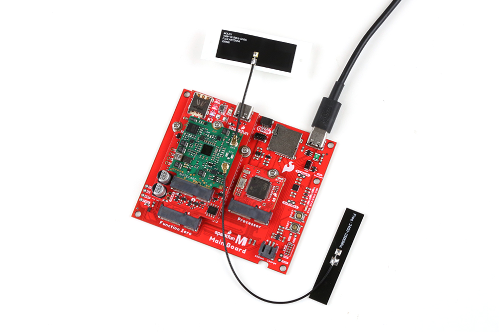
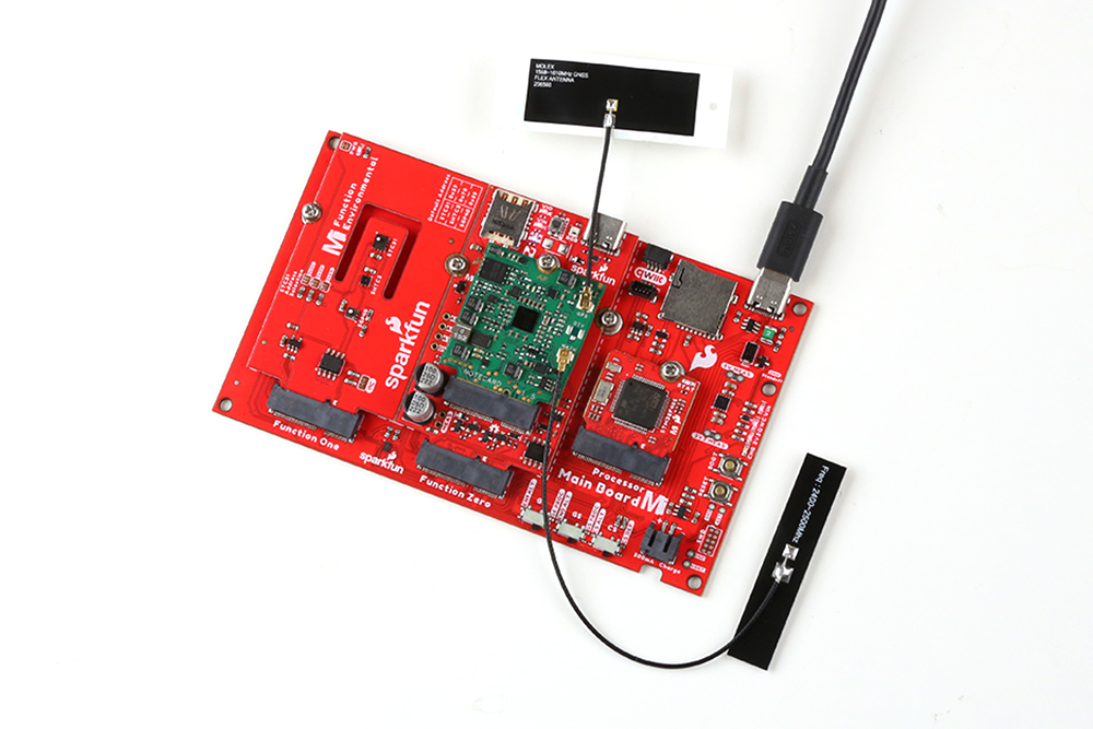
Completed Assembly
Our Arduino example for this Function Board demonstrates how to send environmental data from an Environmental Function Board mounted on the Double Main Board with the Cellular Function Board. The photo below shows a completed MicroMod assembly for that example:
Software Setup
Using the Cellular Function Board in the MicroMod ecosystem requires a few software setup steps before getting started.
Blues Wireless Software
Blues Wireless has several software support packages to help communicate between the Notecard and connected Processor and to communicate between the Notecard and the cloud.
Notehub
Blues Wireless' Notehub.io is a service that routes data from a Notecard to the cloud. Notehub works with a wide range of cloud options like AWS, Azure, Google Cloud. In addition, Notehub can route data to an IoT messaging platform like MQTT or a custom HTTP/HTTPS endpoint. Notehub requires an account tied to your Notecard so make sure to register if you do not have one already.
Once your account is created and verified, click the "Create Project" button in the top right of the page to start a new Project for your Notecard. This opens a pop-up on the page where you enter a Project Name, unique ID and select the billing account tied to the Project. By default, this selects the billing acount tied to your Notehub account but you can select other options in the drop-down menu. Once you have everything selected, select "Create Project".
Blues Wireless Documentation
This tutorial only does a cursory dive into using Notehub with the Function Board. For all the information you'll ever need for Notehub, Blues has written a host of tutorials covering the basics of Notehub as well as how to route data to a wide variety of platforms so be sure to check them out here:
Blues Note Arduino Library
The Blues Note Arduino Library allows users to communicate with a Notecard using the Arduino IDE over serial and I2C. To install the library using the Arduino Library Manager tool, navigate to the Tools menu and click "Manage Libraries" (you can also use the keyboard shortcut of Ctrl + Shift + I) and search for "note-arduino". Users who prefer to manually install the library can find it here on GitHub or you can click the button below to download a ZIP of the library:
Notecard CLI
Blues also offers two options for getting right to work with the Notecard with their in-browser terminal Notecard Playground (Note: the in-browser terminal only runs on Chrome, Opera or Edge browsers). The CLI is also available as a traditional application for download here.
Using the CLI only requires a USB-C cable connecting the Cellular Function Board to your computer. The CLI should automatically detect the Notecard and appear as a selectable device in the drop-down menu in the CLI.
Environmental Function Board Libraries
The Arduino Example in the following section requires the SparkFun Arduino libraries for the SGP40, SHTC3 and STC3X sensors on the Environmental Function Board. Install them with the Arduino Library manager tool by opening it and searching "SparkFun SGP40", "SHTC3" and "STC3X". If you prefer to manually install them you can download them from their GitHub repositories (SGP40, SHTC3, STC3X) or click the buttons below to download a ZIP of the libraries:
SparkFun SHTC3 Arduino Library (ZIP)
SparkFun STC3X Arduino Library (ZIP)
Processor Arduino Board Definitions and Driver
Make sure you go through the Hookup Guide for your chosen Processor Board to install the latest Arduino board definitions and any necessary drivers:
MicroMod Artemis Processor Board Hookup Guide
MicroMod STM32 Processor Hookup Guide
Pin Connection Table
The table below helps show which pins the Function Board connects to depending on the slot it is connected to on a Main Board (Note: The Single Main Board connection is Slot 0):
| AUDIO | UART | GPIO/BUS | I2C | SDIO | SPI0 | Dedicated |
|
Function Board
Pin Name |
Main Board's
Processor Pin |
Slot 0 | Slot 1 |
|---|---|---|
| VCC | - | |
| 3.3V | - | |
| GND | - | |
| PWR_EN | SDIO_DATA2/PWR_EN0_ALT | SDIO_DATA1/PWR_EN1_ALT |
| DFU_RST | RESET | |
| DFU_BOOT | BOOT | |
| DFU_FC_TX | RX1-DFU_TX-FC0-PLEX1 | RX1-DFU_TX-FC1-PLEX1 |
| DFU_FC_RX | TX1-DFU_RX-FC0-PLEX1 | TX1-DFU_RX-FC1-PLEX1 |
| RX | TX1-PROCESSOR-PLEX1 | TX2-PROCESSOR |
| TX | RX1-PROCESSOR-PLEX1 | RX2-PROCESSOR |
| F3 | G0 | G5 |
| F4 | G1 | G6 |
| F5 | G2 | G7 |
Arduino Example
In this section we'll use the MicroMod assembly built in the Hardware Assembly section to use the Notecard to send temperature, pressure, air quality and CO2 data recorded by the Environmental Function Board to notehub.io.
Arduino Code
The example configures the Notecard to receive data over I2C sent to the Processor from the Environmental Fucntion Board. The main loop retrieves data from all three sensors and every fifteen seconds creates a tells the Notecard send the data to notehub.io every fifteen seconds to be recorded as events in the Notehub Project created in the Software Setup section.
Copy the code below into a new sketch in Arduino. Select your board (the example assumes a MicroMod STM32 Processor Board is used) and port and click the Upload button:
language:c
/**
 * @file
 * @brief This example collects sensor data and posts it to NoteHub.
 * @copyright SPDX-License-Identifier: MIT
 * @author Alex Brudner, SparkFun Electronics
 * @date 2022-11-02
 * @note Based on Example01 from the MicroMod Environmental Function Board by
 * Ho Yun "Bobby" Chan. This example code combines example codes from the
 * SHTC3, STC31, and SGP40 libraries. Most of the steps to obtain the
 * measurements are the same as the example code. Generic object names were
 * renamed (e.g. mySensor => mySGP40 and mySTC3x).
 *
 *    Example 1: Basic Relative Humidity and Temperature Readings  w/ SHTC3
 *       Written by Owen Lyke
 *    Example 2: PHT (SHTC3) Compensated CO2 Readings w/ STC31
 *       Written by Paul Clark and based on earlier code by Nathan Seidle
 *    Example 1: Basic VOC Index w/ SGP40
 *       Written by Paul Clark
 *
 * Open a Serial Monitor at 115200 baud to view the readings too!
 *
 * Note: You may need to wait about ~5 minutes after starting up the code
 * before VOC index
 * has any values.
 *
 * ========== HARDWARE CONNECTIONS ==========
 * MicroMod STM32 Processor Board => MicroMod Main Board => MicroMod
 *  Environmental Function Board (with SHTC3, STC31, and SGP40)
 * MicroMod STM32 Processor Board => MicroMod Main Board => MicroMod
 *  Function Board Blues Wireless Notecarrier
 *
 * Feel like supporting open source hardware?
 * Buy a board from SparkFun!
 *      MicroMod Function Board Blues Wireless Notecarrier
 *        | https://www.sparkfun.com/products/20409
 *      MicroMod STM32 Processor
 *        | https://www.sparkfun.com/products/16401
 *      MicroMod Main Board - Double
 *        | https://www.sparkfun.com/products/18575
 *      MicroMod Environmental Function Board
 *        | https://www.sparkfun.com/products/18632
 *
 * You can also get the sensors individually.
 *
 *      Qwiic SHTC3 | https://www.sparkfun.com/products/16467
 *      Qwiic STC31 | https://www.sparkfun.com/products/18385
 *      Qwiic SGP40 | https://www.sparkfun.com/products/17729
 */

/* Notecard Includes */
#include <Arduino.h>
#include <Wire.h>
#include <Notecard.h>

/* Sensor Includes */
#include <SparkFun_SHTC3.h>
#include <SparkFun_STC3x_Arduino_Library.h>
#include <SparkFun_SGP40_Arduino_Library.h>

#define PRODUCT_UID "com.your-company.your-name:your_product"

/* Instantiate Notecard class */
Notecard notecard;
int ncUpdateCtr = 0;

/* Instantiate sensor interface classes */
SHTC3 mySHTC3;
STC3x mySTC3x;
SGP40 mySGP40;

float rh = 0.0;           // Relative Humidity from the SHTC3
float temperature = 0.0;  // Temperature from the SHTC3
float co2 = 0.0;          // %CO2 from STC3
int32_t voc = 0;          // VOC index from SGP40

void setup() {
  /* Begin Serial communications */
  delay(2500);
  Serial.begin(115200);
  Serial.println(F("Begin - MicroMod Notecarrier Example 01: Sensor Data."));
  notecard.setDebugOutputStream(Serial);

  /* Begin I2C communications */
  Wire.begin();

  /* Initialize Notecard */
  notecard.begin();

  /* Configure Notecard */
  J *req = notecard.newRequest("hub.set");
  JAddStringToObject(req, "product", PRODUCT_UID);
  JAddStringToObject(req, "mode", "continuous");
  notecard.sendRequest(req);

  /* Find and initialize sensors */
  if (mySHTC3.begin() != SHTC3_Status_Nominal)
  {
    Serial.println(F("SHTC3 not detected. Please check wiring. Freezing..."));
    while (1)
      ; // Do nothing more
  }

  if (!mySTC3x.begin())
  {
    Serial.println(F("STC3x not detected. Please check wiring. Freezing..."));
    while (1)
      ; // Do nothing more
  }

  if (!mySGP40.begin())
  {
    Serial.println(F("SGP40 not detected. Check connections. Freezing..."));
    while (1)
      ; // Do nothing more
  }

  /**
   * We need to tell the STC3x what binary gas and full range we are using
   * Possible values are:
   * STC3X_BINARY_GAS_CO2_N2_100   : Set binary gas to CO2 in N2.
   *    Range: 0 to 100 vol%
   * STC3X_BINARY_GAS_CO2_AIR_100  : Set binary gas to CO2 in Air.
   *    Range: 0 to 100 vol%
   * STC3X_BINARY_GAS_CO2_N2_25    : Set binary gas to CO2 in N2.
   *    Range: 0 to 25 vol%
   * STC3X_BINARY_GAS_CO2_AIR_25   : Set binary gas to CO2 in Air.
   *    Range: 0 to 25 vol%
   */
  if (!mySTC3x.setBinaryGas(STC3X_BINARY_GAS_CO2_AIR_25))
  {
    Serial.println(F("ST3x - Could not set the binary gas! Freezing..."));
    while (1)
      ; // Do nothing more
  }

  /**
   * Get an initial measurement so we can compensate for temperature and
   * relative humidity using the readings from the SHTC3
   */
  if (mySHTC3.update() != SHTC3_Status_Nominal) // Request a measurement
  {
    Serial.println(F("Could not read the RH and T from the SHTC3! \\
Freezing..."));
    while (1)
      ; // Do nothing more
  }

  /**
   * Configure STC31 temperature compensation based on previous measurement.
   * In case the ‘Set temperature command’ has been used prior to the above
   * measurement command, this will set a new temperature compensation point.
   */
  temperature = mySHTC3.toDegC();
  Serial.print(F("Setting STC3x temperature to "));
  Serial.print(temperature, 2);
  Serial.print(F("C was "));
  if (!mySTC3x.setTemperature(temperature))
    Serial.print(F("not "));
  Serial.println(F("successful"));

  /**
   * Configure STC31 humidity compensation based on previous measurement.
   * In case the ‘Set humidity command’ has been used prior to the above
   * measurement command, this will set a new humidity compensation point.
   */
  rh = mySHTC3.toPercent();
  Serial.print(F("Setting STC3x RH to "));
  Serial.print(rh, 2);
  Serial.print(F("% was "));
  if (!mySTC3x.setRelativeHumidity(rh))
    Serial.print(F("not "));
  Serial.println(F("successful"));

  /**
   * If we have a pressure sensor available, we can compensate for ambient
   * pressure too.
   * As an example, let's set the pressure to 840 mbar (== SF Headquarters)
   */
  uint16_t pressure = 840;
  Serial.print(F("Setting STC3x pressure to "));
  Serial.print(pressure);
  Serial.print(F("mbar was "));
  if (mySTC3x.setPressure(pressure) == false)
    Serial.print(F("not "));
  Serial.println(F("successful"));

  Serial.println(F("Note: Relative humidity and temperature compensation for the STC31 will be updated frequently in the main loop() function."));

}

void loop() {

  //================================
  //==========READ SHTC3============
  //================================
  /* minimum update rate = ~100Hz */

  SHTC3_Status_TypeDef result = mySHTC3.update();           // Call "update()" to command a measurement, wait for measurement to complete, and update the RH and T members of the object

  rh = mySHTC3.toPercent();                                 // "toPercent" returns the percent humidity as a floating point number
  Serial.print(F("RelH: "));
  Serial.print(rh);
  Serial.println(F("%"));

  temperature = mySHTC3.toDegC();
  Serial.print(F("T: "));
  Serial.print(temperature);
  Serial.print(F(" deg C"));

  if (mySHTC3.lastStatus == SHTC3_Status_Nominal)           // You can also assess the status of the last command by checking the ".lastStatus" member of the object
  {
    Serial.println("");                                         //Sample data good, no need to output a message
  }
  else {
    Serial.print(F(",     Update failed, error: "));        //notify user if there is an error
    errorDecoder(mySHTC3.lastStatus);
    Serial.println("");
  }


  //==============================
  //==========READ STC31==========
  //==============================
  /* minimum update rate = 1Hz */


  if (!mySTC3x.setRelativeHumidity(rh))
    Serial.print(F("Unable to set STC31 Relative Humidity with SHTC3."));

  if (!mySTC3x.setTemperature(temperature))
    Serial.println(F("Unable to set STC31 Temperature with SHTC3."));


  Serial.print(F("CO2(%): "));

  if (mySTC3x.measureGasConcentration())                   // measureGasConcentration will return true when fresh data is available
  {
    co2 = mySTC3x.getCO2();
    Serial.println(co2, 2);
  }
  else
  {
    co2 = mySTC3x.getCO2();
    Serial.print(co2, 2);
    Serial.println(F(",     (old STC3 sample reading, STC31 was not able to get fresh data yet)"));  //output this note to indicate  when we are not able to obtain a new measurement
  }


  //==============================
  //==========READ SGP40==========
  //==============================
  /* minimum update rate = 1Hz */
  Serial.print(F("VOC: "));
  voc = mySGP40.getVOCindex(rh, temperature);
  Serial.println(voc);

  /* Update the notecard about every 15s.*/
  if(++ncUpdateCtr >= 14)
  {
    ncUpdateCtr = 0;
    //==============================
    //=========UPLOAD DATA==========
    //==============================
    J *req = notecard.newRequest("note.add");
    if (req != NULL) {
      JAddStringToObject(req, "file", "sensors.qo");
      JAddBoolToObject(req, "sync", true);

      J *body = JCreateObject();
      if (body != NULL) {
        JAddNumberToObject(body, "temperature", temperature);
        JAddNumberToObject(body, "humidity", rh);
        JAddNumberToObject(body, "CO2%", co2);
        JAddNumberToObject(body, "VOC", voc);
        JAddItemToObject(req, "body", body);
      }

      notecard.sendRequest(req);
    }
  }

  //================================
  //=========SPACE & DELAY==========
  //================================
  Serial.println("");// Uncomment this line to add some space between readings for the Serial Monitor
  delay(1000); //Wait 1 second - the Sensirion VOC and CO2 algorithms expects a sample rate of 1Hz

}

void errorDecoder(SHTC3_Status_TypeDef message)                             // The errorDecoder function prints "SHTC3_Status_TypeDef" results in a human-friendly way
{
  switch (message)
  {
    case SHTC3_Status_Nominal : Serial.print("Nominal"); break;
    case SHTC3_Status_Error : Serial.print("Error"); break;
    case SHTC3_Status_CRC_Fail : Serial.print("CRC Fail"); break;
    default : Serial.print("Unknown return code"); break;
  }
}
Notehub Project
First we'll return to the Notehub project created in the Software Setup section. If you haven't already, open notehub.io and open your Project. Your Notecard should appear in the devices listed.
Now open the Events tab and you should see a list of events printed out in the window assuming your Notes have synced.
This is just a basic example of transmitting data with the Notecard. From here you can route data to any of the supported cloud platforms. Head over to Blues Wireless' routing tutorials for detailed instructions on how to do that.
Outboard Device Firmware Update
Now that we're familiar with routing data through the Notecard to notehub.io, we'll demo one of the Notecard's most unique features; outboard device firmware updates (DFU). Outboard DFU's allow the Notecard to upload firmware to a connected Processor Board remotely from any location with a cellular signal. In this section we'll use notehub and Arduino to upload a new sketch to an STM32 Processor v20.
Configure Notecard for Outboard DFU
The Outboard DFU setting should be enabled on your Notecard by default but if you want to make sure send the following request to it through the Notecard CLI: {"req":"dfu.status","on":true}.
Next, enable the Notecard to flash the STM32 Processor with the binary we'll create later with the card.dfu request. Since we're flashing the STM32 Processor, the request should look something like this: {"req":"card.dfu","name":"stm32","on":true}.
Generate the Firmware Binary
With Outboard DFU enabled, we need to generate and locate the binary file created by Arduino for the firmware to be uploaded to the STM32 Processor. Open the Arduino IDE and copy the code below into a blank sketch. Alternatively, you can find it in the examples folder of the Function Board's Hardware Github Repo.
language:c
/**
 * @file Example02_Outboard_DFU.ino
 * @brief This example performs an Outboard Device Firmware Update.
 * @copyright SPDX-License-Identifier: MIT
 * @author Alex Brudner, SparkFun Electronics
 * @date 2022-11-02
 * @note Based on the DFU example from Blues Wireless. See
 * https://github.com/blues/note-outboard-dfu
 *
 * ========== HARDWARE CONNECTIONS ==========
 * MicroMod STM32 Processor Board => MicroMod Main Board => MicroMod
 *  Function Board Blues Wireless Notecarrier
 *
 * Feel like supporting open source hardware?
 * Buy a board from SparkFun!
 *      MicroMod Function Board Blues Wireless Notecarrier
 *        | https://www.sparkfun.com/products/20409
 *      MicroMod STM32 Processor
 *        | https://www.sparkfun.com/products/16401
 *      MicroMod Main Board - Double
 *        | https://www.sparkfun.com/products/18575
 */

#include <Arduino.h>
#include <Notecard.h>

#define PRODUCT_UID "com.your-company.your-name:your_product"

int ledPin = LED_BUILTIN;

Notecard notecard;

void setup()
{
    pinMode(ledPin, OUTPUT);

    /* Begin Serial communications */
    Serial.begin(115200);
    Serial.println(F("Begin - MicroMod Notecarrier Example 02: Outboard DFU"));
    notecard.setDebugOutputStream(Serial);

    /* Begin Serial communications */
    Wire.begin();
    notecard.begin();

    /* Configure Notecard */
    J *req = notecard.newRequest("hub.set");
    JAddStringToObject(req, "product", PRODUCT_UID);
    JAddStringToObject(req, "mode", "continuous");
    JAddStringToObject(req, "sn", "stm32-micromod-v20-SN0001");
    notecard.sendRequest(req);

    /* Configure DFU settings */
    req = notecard.newRequest("card.dfu");
    JAddStringToObject(req, "name", "stm32-bi"); /* bi == boot inversion */
    JAddBoolToObject(req, "on", true);
    notecard.sendRequest(req);
}

void loop()
{
    /* Fast Blink LED while waiting for DFU. */
    Serial.println("Hello, world!");
    digitalWrite(ledPin, HIGH);
    delay(100);
    digitalWrite(ledPin, LOW);
    delay(400);
}
During verification, Arduino creates a temporary folder with this binary file along with other necessary metadata. On Windows, this is commonly in a filepath similar to: Users/"Your Username"/AppData/Local/Temp. When you open the Temp folder, you may have several folders titled arduino_build_######. If you can't find it there or use another operating system, Arduino prints the file location in the output data during the compilation step with "Verbose Output" enabled.
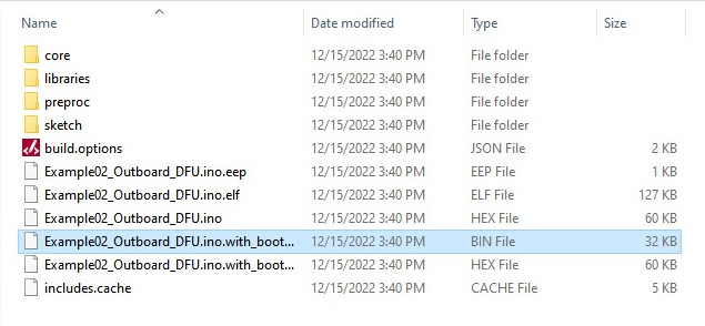
Open the folder containing the binary file, we'll need file location later. Alternatively, you can copy/paste it into a more easily accessible location.
Upload Binary to Notehub
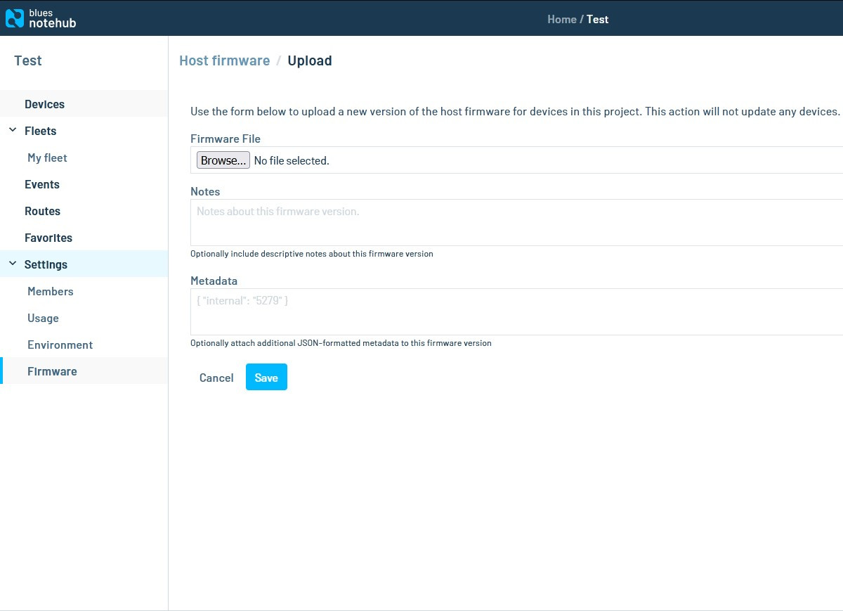
Now we need to upload the binary file of the firmware to Notehub.io. Log in to your Notehub account if you have not already and navigate to the "Firmware" option below "Settings". Click the Firmware File field and navigate to the firmware binary location and click "Open". This page also includes the ability to add any notes regarding the firmware update as well as any metadata you wish to include with it. We'll skip both of those for now in this demo.
With the firmware saved to Notehub, go back to the Devices page.
Update Device Firmware
Select your Notecard and select to the "Host Firmware" tab. Next, click the "Update" button on the far right of the screen and it should open a prompt asking you to confirm you want to update the firmware. Click "Proceed", select the firmware from the list (in our case it will only include the "Example02_Outboard_DFU" binary) and click "Apply".

Your Notecard should automatically start to try and update the new firmware. You can watch the status of the firmware update in the "Host Firmware" tab.
Now that you're familiar with how to perform Outboard DFU's, you can upload your own custom firmware to your Processor.
Troubleshooting
Notecard CLI Helpful Commands
The Notecard CLI has a lot of helpful commands for debugging and troubleshooting all sorts of issues with the Notecard. Below is a list of just a few commands we find particularly helpful as starting points for troubleshooting but for a complete list as well as tutorials on how to use them, head over to Blues Wireless' Developers Page.
Simply connect the Cellular Function Board - Blues Wireless Notecarrier to your computer via the USB-C connector on the Function Board and open the Notecard CLI either in a browser or on your computer to start troubleshooting your board directly:
- '{"req": "card.version"}' - Request returns information on the Notecard version including the hardware version, device ID, name and firmware version.
- '{"req": "card.wireless"}' - Returns cellular connection data such as RSRP/RSRQ, RSSI, modem and band type and much more. Very helpful for diagnosing cellular activity issues.
- '{"req:" "hub.sync"}' - Manually sync the Notecard with Notehub. Pair this with the following request to view the synchronization status of the Notecard with Notehub.
- '{"req": "hub.sync.status"} - Returns helpful information about the status of communication between the Notecard and Notehub.
Notecard Firmware Version and Updating
If you run into any issues with features on notehub.io such as Outboard DFU the first thing we recommend checking is your Notecard firmware version. Verify the firmware version on the Notecard supports the features you are attempting to use and if needed, update the firmware on Notehub. You can find a step-by-step tutorial for updating Notecard firmware here.
Outboard DFU Hardware Limitations
As mentioned previously, Outboard DFU with the Cellular Function Board - Blues Wireless Notecarrier only works with specific MicroMod hardware:
- SparkFun MicroMod Main Board - Single v21 or SparkFun MicroMod Main Board - Double v22
- STM32 v20 Processor
This feature may work on other Processors in the future and we will update this guide when and if those Processors are added. Note, the previous versions of both MicroMod Main Boards do not support Outboard DFU with the Cellular Function Board - Blues Wireless Notecarrier.
General Troubleshooting
If you need technical assistance and more information on a product that is not working as you expected, we recommend heading on over to the SparkFun Technical Assistance page for some initial troubleshooting.
If you don't find what you need there, the SparkFun Forums are a great place to find and ask for help. If this is your first visit, you'll need to create a Forum Account to search product forums and post questions.
Resources and Going Further
That's all for this tutorial. For more information on the MicroMod Cellular Function Board - Blues Wirless Notecard, take a look at the resources below:
Cellular Function Board Resources:
Blues Wireless Resources:
- Notecard NOTE-NBGL-500 Datasheet
- Notecard CLI
- Notehub Walkthrough
- Blues Note Arduino Library
- Blues Note Python Library
MicroMod Resources: