CC3000 Hookup Guide
This Tutorial is Retired!
This tutorial covers concepts or technologies that are no longer current. It's still here for you to read and enjoy, but may not be as useful as our newest tutorials.
Board Overview
CC3000 Shield
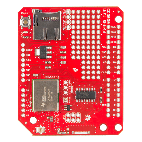
The CC3000 Shield has a standard Arduino shield layout with 2 rows of pins on either side. The right-side headers have been broken out on the shield if you want to solder headers or wires for easy prototyping.
On the top-left, there is a microSD card which will work with Arduino's SD library (note that you will need to change the chipSelect variable to pin 8 for the CC3000 Shield). To the left of the microSD slot is a RESET button, should you need to reset the Arduino. To the right of the microSD slot, you will find a prototyping area filled with 0.100 inch holes and the following voltages broken out: GND, 3.3V, 5V, and Vin (the input voltage to the Arduino).
Below the microSD slot is a 3.3V regulator and the CC3000 module, which is connected to the antenna section at the bottom of the board. By default the CC3000 is connected to the chip antenna, but you can move the Antenna Select capacitor if you want to Bring Your Own Antenna. To the right of the CC3000 module is a level shifter that allows the 3.3V logic of the CC3000 to communicate with the 5V logic normally found on the Arduino.
The pins used by the shield are as follows:
2 (INT) is the interrupt pin that the CC3000 uses to notify the Arduino that it has data.
7 (EN) is the enable pin that the Arduino uses to turn the CC3000 off and on.
8 (SDCS) is the chip select for the SD card.
10 (CS) is the chip select for the CC3000.
11 (MOSI) is the SPI communication line from the Arduino to the CC3000.
12 (MISO) is the SPI communication line from the CC3000 to the Arduino.
13 (SCK) is the SPI clock line.
CC3000 Breakout Board
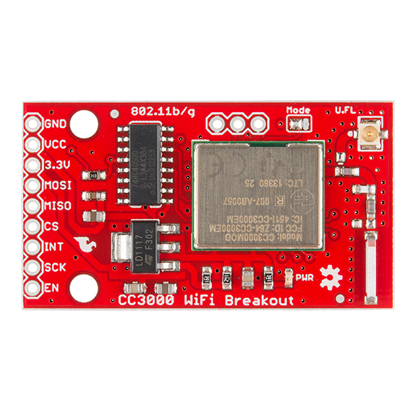
As opposed to the Shield, the CC3000 Breakout Board contains just the CC3000 module, an antenna section, a voltage regulator, and a level shifter. It can work with any 3.3V or 5V logic microcontroller that can communicate via SPI.
GND should be connected to the host circuit's ground.
VCC is the supply voltage and should be connected to 4.3V - 15V if you are unable to provide 3.3V to the board.
3.3V should be connected to a 3.3V power source if one is available. IMPORTANT: only one of VCC or 3.3V should be connected.
MOSI should be connected to the SPI MOSI pin of the host microcontroller.
MISO should be connected to the SPI MISO pin of the host microcontroller.
CS should be connected to a SPI chip select pin of the host microcontroller.
INT should be connected to a pin capable of external interruptrs on the microcontroller.
SCK should be connected to the SPI clock line of the host microcontroller.
EN should be connected to any GPIO pin on the microcontroller.

