CC3000 Hookup Guide
This Tutorial is Retired!
This tutorial covers concepts or technologies that are no longer current. It's still here for you to read and enjoy, but may not be as useful as our newest tutorials.
Introduction
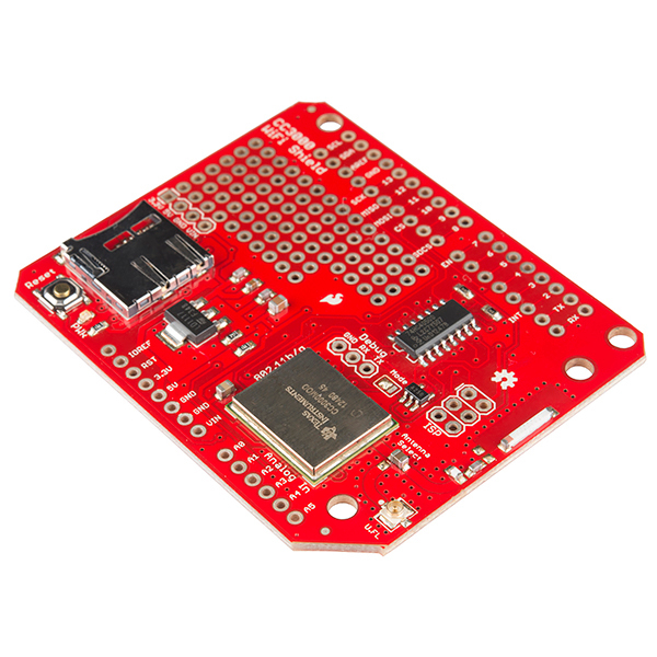
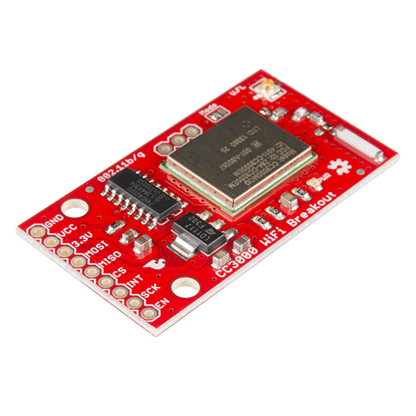
If you need to add wireless networking (WiFi) to a project, then the CC3000 could be your ticket. Two flavors are available: the CC3000 WiFi Arduino Shield, and the CC3000 WiFi Breakout Board. What sets the CC3000 apart from others (such as the WiFly Shield) is its ability to associate to a WiFi access point (AP) using a cell phone app in a process TI calls SmartConfig.
This guide will walk you through the getting started process with the CC3000 Shield and Breakout Board.
Required Materials
- CC3000 Shield or CC3000 Breakout Board
- Arduino, RedBoard or any Arduino-compatible board
- Male PTH headers or Arduino Stackable Headers
If you are using the breakout board (as opposed to the shield), you will also need:
- Jumper wires to connect from breadboard to Arduino
- Breadboard to tie everything together
If you want to connect an external antenna, you need:
Suggested Reading
Board Overview
CC3000 Shield
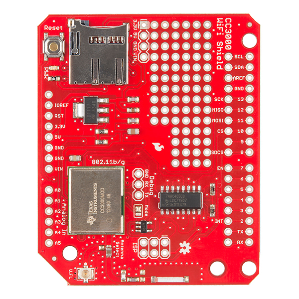
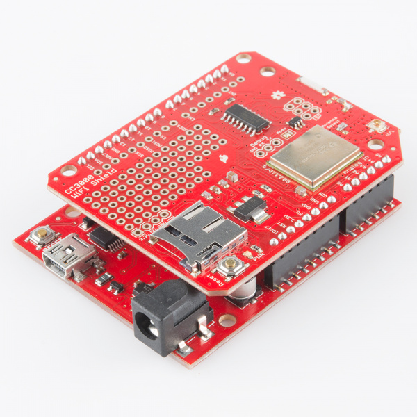
The CC3000 Shield has a standard Arduino shield layout with 2 rows of pins on either side. The right-side headers have been broken out on the shield if you want to solder headers or wires for easy prototyping.
On the top-left, there is a microSD card which will work with Arduino's SD library (note that you will need to change the chipSelect variable to pin 8 for the CC3000 Shield). To the left of the microSD slot is a RESET button, should you need to reset the Arduino. To the right of the microSD slot, you will find a prototyping area filled with 0.100 inch holes and the following voltages broken out: GND, 3.3V, 5V, and Vin (the input voltage to the Arduino).
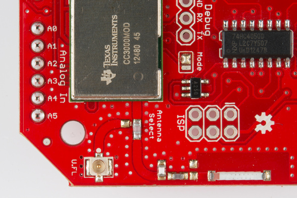
Below the microSD slot is a 3.3V regulator and the CC3000 module, which is connected to the antenna section at the bottom of the board. By default the CC3000 is connected to the chip antenna, but you can move the Antenna Select capacitor if you want to Bring Your Own Antenna. To the right of the CC3000 module is a level shifter that allows the 3.3V logic of the CC3000 to communicate with the 5V logic normally found on the Arduino.
The pins used by the shield are as follows:
2 (INT) is the interrupt pin that the CC3000 uses to notify the Arduino that it has data.
7 (EN) is the enable pin that the Arduino uses to turn the CC3000 off and on.
8 (SDCS) is the chip select for the SD card.
10 (CS) is the chip select for the CC3000.
11 (MOSI) is the SPI communication line from the Arduino to the CC3000.
12 (MISO) is the SPI communication line from the CC3000 to the Arduino.
13 (SCK) is the SPI clock line.
CC3000 Breakout Board
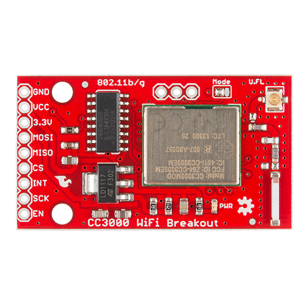
As opposed to the Shield, the CC3000 Breakout Board contains just the CC3000 module, an antenna section, a voltage regulator, and a level shifter. It can work with any 3.3V or 5V logic microcontroller that can communicate via SPI.
GND should be connected to the host circuit's ground.
VCC is the supply voltage and should be connected to 4.3V - 15V if you are unable to provide 3.3V to the board.
3.3V should be connected to a 3.3V power source if one is available. IMPORTANT: only one of VCC or 3.3V should be connected.
MOSI should be connected to the SPI MOSI pin of the host microcontroller.
MISO should be connected to the SPI MISO pin of the host microcontroller.
CS should be connected to a SPI chip select pin of the host microcontroller.
INT should be connected to a pin capable of external interruptrs on the microcontroller.
SCK should be connected to the SPI clock line of the host microcontroller.
EN should be connected to any GPIO pin on the microcontroller.
Hardware Hookup
You can use either the CC3000 Shield or the CC3000 Breakout for the examples in this tutorial.
CC3000 Shield
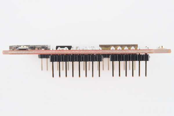
Solder Arduino stackable headers or break away headers to the shield.
Attach the shield to the Arduino.
CC3000 Breakout
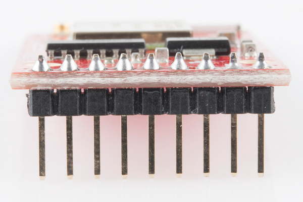
Solder break away headers to the 9 header holes on the board.
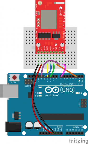
Connect the breakout board to the following Arduino pins:
(CC3000 Breakout Board → Arduino)
- GND → GND
- VCC → 5V
- MOSI → 11
- MISO → 12
- CS → 10
- INT → 2
- SCK → 13
- EN → 7
Connecting an External Antenna
IMPORTANT: This step is optional! You don't need to add an external antenna to get the CC3000 to work (the chip antenna on the shield and breakout board works well enough). Only do this if you need to add an external antenna.
Both the CC3000 Shield and Breakout Board offer the ability to attach an external antenna. This is a handy feature if you want to route an antenna to the outside of an enclosure or to increase your WiFi gain.
Shield
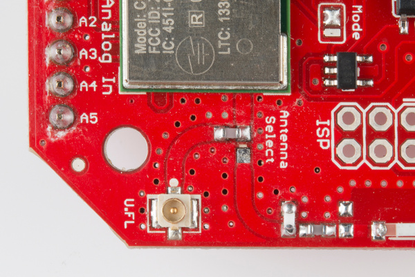
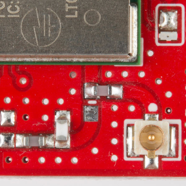
Desolder the capacitor labeled "Antenna Select."
Rotate the capacitor at a 90° angle so that it is connecting the trace coming out of the CC3000 and the trace going to the U.FL connector.
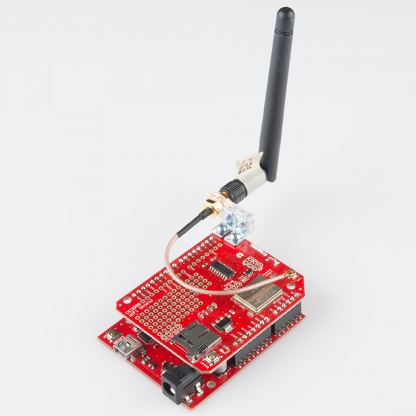
Attach the RP-SMA to U.FL cable to the U.FL connector. Connect the 2.4GHz antenna (or 2.4GHz large antenna) to the cable.
Note that you can use some Angle Brackets, 4-40 Screws, 4-40 Nuts, and a piece of drilled (or laser-cut) plastic to hold the antenna onto the CC3000 Shield.
Breakout Board
For the CC3000 Breakout Board, you will need to perform the same operation as on the shield to rotate the Antenna Select capacitor by 90°.
You may then connect an antenna to the U.FL connector.
CC3000 Library Installation
If you have the Arduino program open, close it now.
Download the SFE CC3000 Library from the GitHub repository here: SFE_CC3000_Library-master
Right-click on the .zip file and select "Extract All..." to unzip the library.
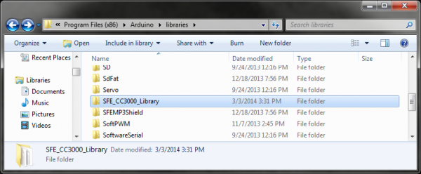
Copy the newly extracted folder into your (Arduino isntallation directory)\libraries (e.g. C:\Program Files (x86)\Arduino\libraries) folder.
WebClient Example
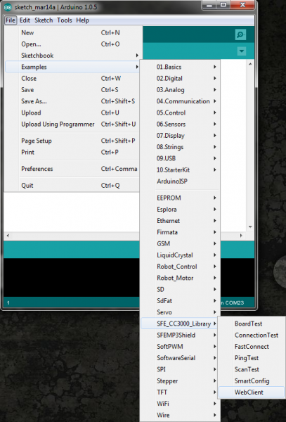
Open up the Arduino program and select File → Examples → SFE_CC3000_Library → WebClient.
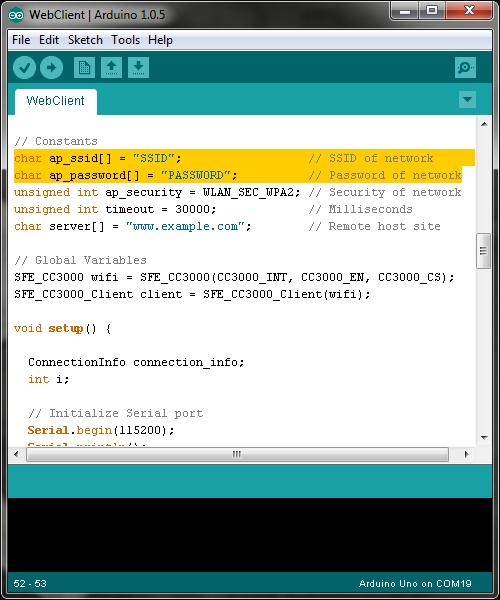
Scroll down to the Constants section and change the ap_ssid[] and ap_password[] variables to match the SSID (network name) and password of your wireless network. If you are using a security protocol other than WPA2, make sure you change ap_security to one of
- WLAN_SEC_UNSEC for unsecured networks
- WLAN_SEC_WEP for networks using WEP
- WLAN_SEC_WPA for networks using WPA
- WLAN_SEC_WPA2 for networks using WPA2
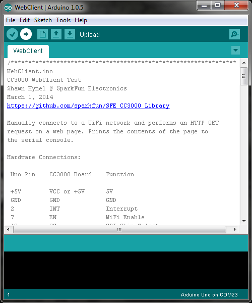
Plug in your Arduino board via USB cable, and select the correct COM port and Board type that corresponds to your Arduino. Click the "Upload" button.
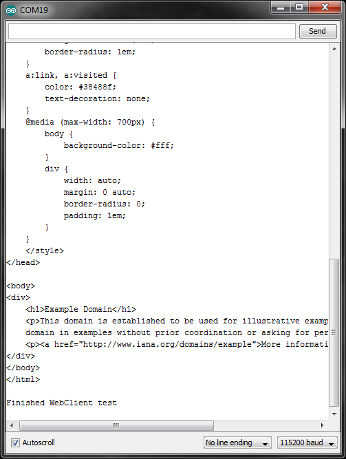
Go to Tools → Serial Monitor and change the baud rate to 115200 baud. Wait while the program tries to connect to the specified access point and perform a GET request of www.example.com. If the test succeeds, you should see HTML print out on the Serial Monitor.
Install SmartConfig App
One of the most appealing features of the CC3000 is its ability to receive AP connection information from a smartphone app. If you are working on a final product or a project that might be changing WiFi networks often, having a way to connect to a new network without re-programming the microcontroller is extremely handy.
iPhone Installation
For iPhone users, download the free app from the iTunes store: TI WiFi SmartConfig
Android Installation
If you have an Andoid phone, the installation process is more involved:
Download the Android SmartConfig Application here. Note: if the download link does not work, go to TI's CC3000 Wi-Fi Downloads page and navigate to the "CC3000 SmartConfig" section to download the "Android SmartConfig Application."
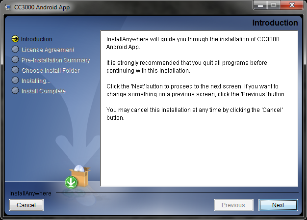
Run the self-extracting .exe and accept the defaults. The program will unzip a series of folders to C:\TI\CC3000AndroidApp.
Using a USB cable, plug your phone into your computer.
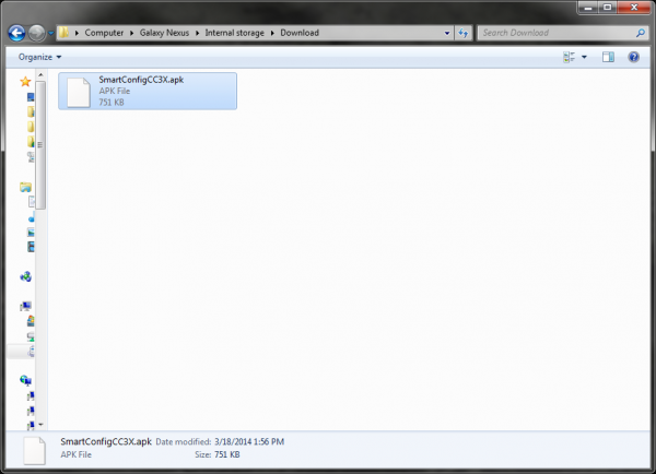
Navigate to C:\TI\CC3000AndroidApp\SmartConfigCC3X\bin and copy SmartConfigCCX.apk to the Internal Storage of your Android phone (e.g. Galaxy Nexus\Internal storage\Download).
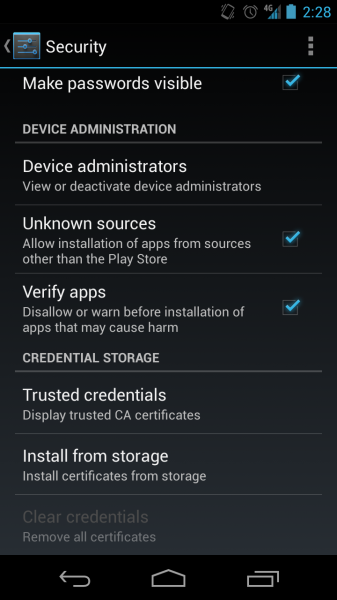
On your phone, go to Settings → Security, and check "Unknown sources" to allow the installation of the .apk file.
Using the Google Play store, install a file browser, such as File Manager.
Open up the File Manager app and navigate to /storage/emulated/0/Download. Click on the SmartConfigCC3X.apk.
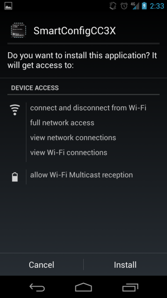
After reviewing the installation page, click "Install."
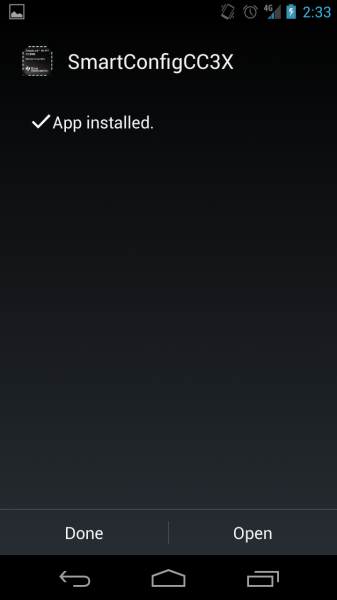
Once the app has installed, click "Done."
SmartConfig and FastConnect
This example requires two different Arduino programs but illustrates the steps necessary to use TI's SmartConfig procedure. You could create a program that combines SmartConfig and FastConnect to allow users the option of selecting which method to connect to a network.
When the SmartConfig procedure is run, the CC3000 creates a connection profile in non-volatile memory (note that all previous connection profiles are deleted). The connection profile can be recalled later (even if the CC3000 and Arduino lose power!) to perform the FastConnect procedure, which allows the CC3000 to connect to the last access point stored in memory.
IMPORTANT: You must run the SmartConfig example before you run FastConnect!
SmartConfig
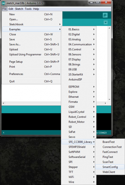
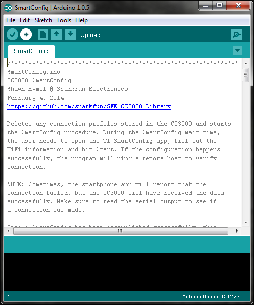
Connect the CC3000 Shield or Breakout Board to an Arduino. Open the Arduino program and select File → Examples → SFE_CC3000_Library → SmartConfig.
Plug in your Arduino board via USB cable, and select the correct COM port and Board type that corresponds to your Arduino. Click the “Upload” button.
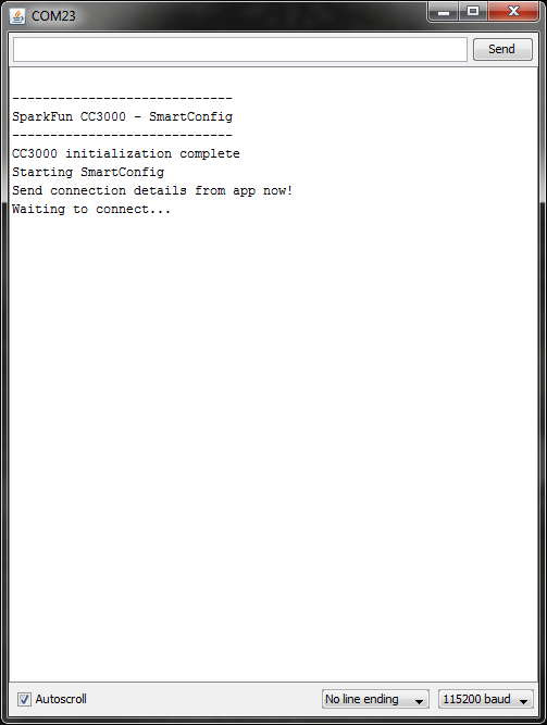
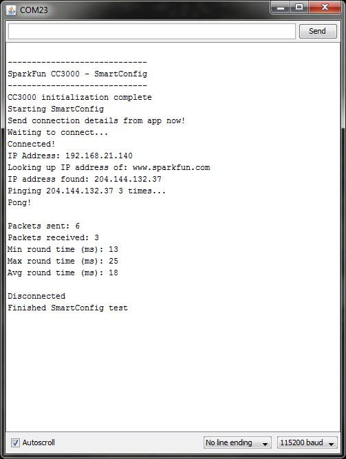
Go to Tools → Serial Monitor and change the baud rate to 115200 baud. The program will print "Send connection details from app now!" and you will have 30 seconds to send connection info from the SmartConfig phone app.
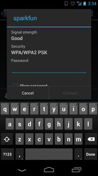
On your phone, go to Settings → WiFi (on either iPhone and Android) and connect to a wireless access point (enter your network's password if asked).
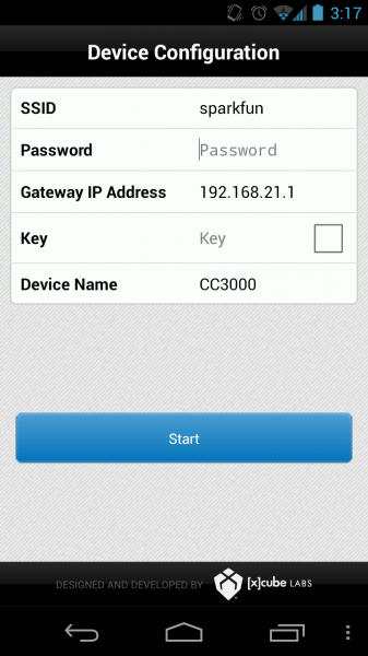
Open the SmartConfig app and enter your network's password. Click "Start."
IMPORTANT: You need to click "Start" while the SmartConfig Arduino program is running and is "Waiting to connect..." If the Arduino program times out (you will see Errors printed in the Serial Monitor), reset the Arduino and try clicking "Start" in the phone app again.
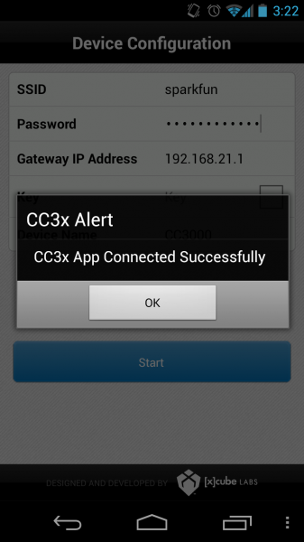
If the CC3000 successfully received the connection packet from the SmartConfig app, you should see a "Connected Successfully" message appear in the app window (note: sometimes this message does not appear, but the CC3000 connects anyway. If this happens, just click "Stop" in the app).
If everything worked, the CC3000 will connect to an access point and ping www.sparkfun.com, which will be reported in the Serial Monitor.
FastConnect
Once you have successfully run the SmartConfig procedure, a connection profile will be stored on the CC3000. We can use that profile to reconnect to an AP by calling fastConnect() in the CC3000 Library. This example illustrates how to use FastConnect.
IMPORTANT: Do not reset the Arduino after running SmartConfig! Leave the Serial Monitor up after a successful SmartConfig and proceed directly to uploading the FastConnect example. If the Arduino is reset, startSmartConfig() will be called, which automatically deletes any connection profiles in memory.
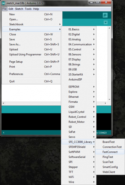
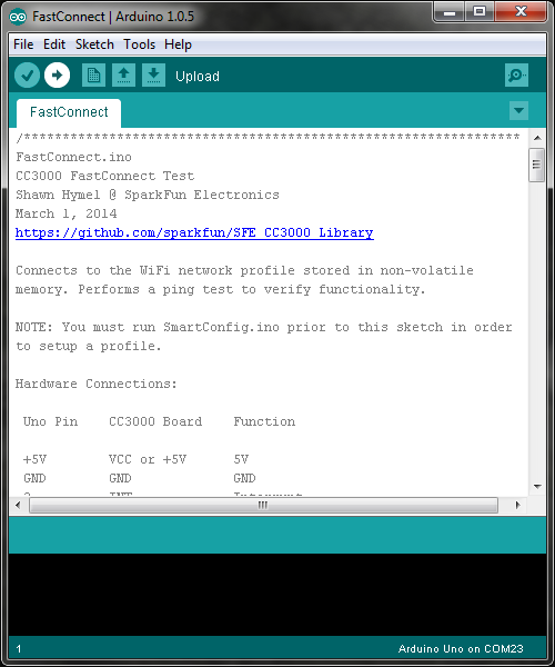
Open the Arduino program and select File → Examples → SFE_CC3000_Library → FastConnect.
Make sure that the correct COM port and correct Arduino board are still selected unded Tools. Click the "Upload" button.
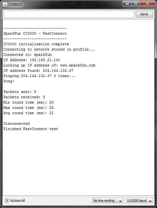
Go to Tools → Serial Monitor and ensure that the baude rate is 115200 baud. If the FastConnect is successful, it should connect to the network setup by the SmartConfig example and ping www.sparkfun.com.
If you would like to see how the connection profiles work using non-volatile memory, unplug the Arduino's USB cable for a few seconds and then plug it back in before running the FastConnect sketch again. You will see how FastConnect can connect to a stored profile even if the Arduino and CC3000 lose power!
Resources and Going Further
The CC3000 provides an easy-to-use WiFi client to any project that contains a SPI bus and a few GPIO lines. The example library was written for Arduino, but the CC3000 can be used with almost any microcontroller. To read more about the CC3000, refer to the following sites:
- TI's CC3000 Main Page
- TI's CC3000 Wiki
- Updating the CC3000's Firmware (Note: this requires an MSP430 Launchpad)
- Understanding the CC3000 library
- Writing your own CC3000 library
- TI's Basic WiFi Application example for the MSP430
