Button Pad Hookup Guide
Contributors:
 Byron J.
Byron J. 
Exercise #3: RGB LEDs and Buttons
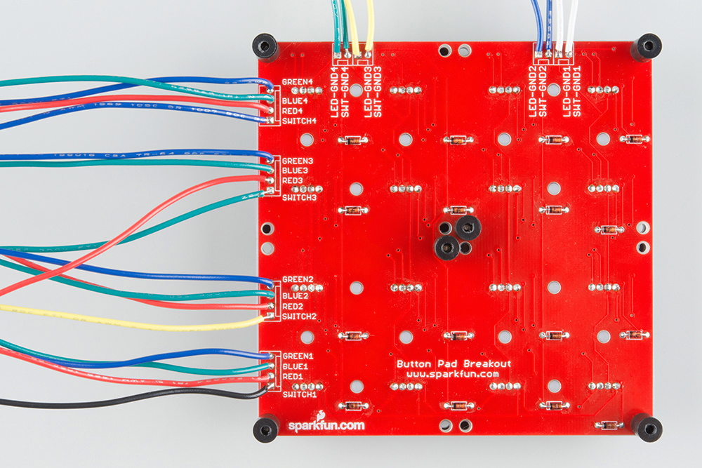
Wiring
Hang in there, only 8 more wires to go!
With the red LEDs and buttons working, let's finish up by adding the blue and green LEDs to the mix.
| Function | Wire Color | Button Pad Connection | Mega Connection |
| Green Row 1 | Green | Blue1* | 24 |
| Blue Row 1 | Blue | Green1* | 26 |
| Green Row 2 | Green | Blue2* | 31 |
| Blue Row 2 | Blue | Green2* | 32 |
| Green Row 3 | Green | Blue3* | 34 |
| Blue Row 3 | Blue | Green3* | 35 |
| Green Row 4 | Green | Blue4* | 37 |
| Blue Row 4 | Blue | Green4* | 38 |
* Keep in mind that the LEDs we've used have their green and blue legs transposed when referencing the PCB markings. Yes, we are intentionally swapping green and blue in the wiring!
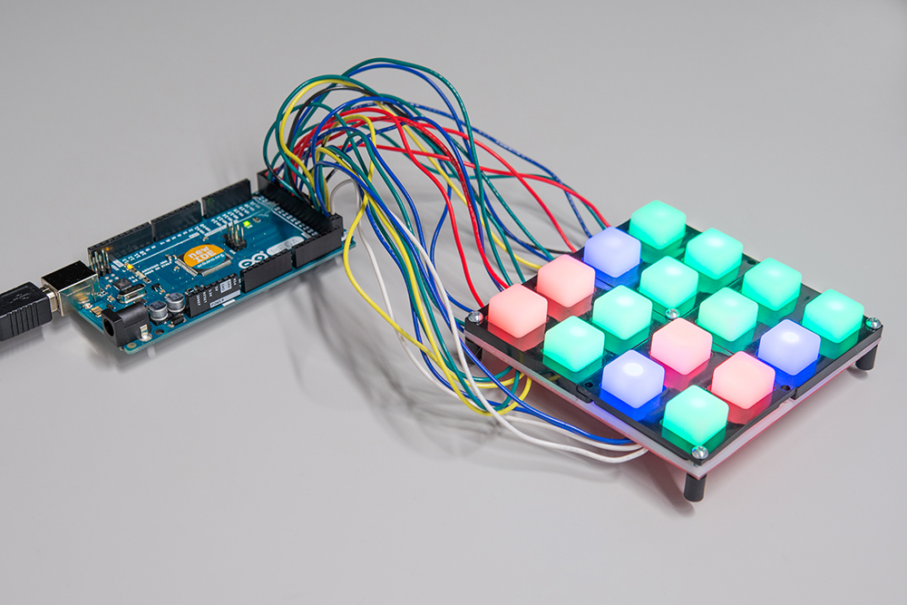
With all of these wires, it's starting to look like a bird's nest!
Code
The final sketch builds on the previous two.
language:c

/******************************************************************************
rgb-plus-buttons.ino
Byron Jacquot @ SparkFun Electronics
1/6/2015

Example to drive the RGB LEDs and scan the buttons of the RGB button pad.

Exercise 3 in a series of 3.
https://learn.sparkfun.com/tutorials/button-pad-hookup-guide/exercise-3-rgb-leds-and-buttons

Development environment specifics:
Developed in Arduino 1.6.5
For an Arduino Mega 2560

This code is released under the [MIT License](http://opensource.org/licenses/MIT).

Distributed as-is; no warranty is given.
******************************************************************************/
//config variables
#define NUM_LED_COLUMNS (4)
#define NUM_LED_ROWS (4)
#define NUM_BTN_COLUMNS (4)
#define NUM_BTN_ROWS (4)
#define NUM_COLORS (3)

#define MAX_DEBOUNCE (3)

// Global variables
static uint8_t LED_outputs[NUM_LED_COLUMNS][NUM_LED_ROWS];
static int32_t next_scan;

static const uint8_t btnselpins[4]   = {50,51,52,53};
static const uint8_t btnreadpins[4] = {46,47,48,49};
static const uint8_t ledselpins[4]   = {42,43,44,45};

// RGB pins for each of 4 rows
static const uint8_t colorpins[4][3] = {{22,24,26}, {30,31,32},{33,34,35},{36,37,38}};


static int8_t debounce_count[NUM_BTN_COLUMNS][NUM_BTN_ROWS];

static void setuppins()
{
    uint8_t i;

    // initialize
    // select lines
    for(i = 0; i < NUM_LED_COLUMNS; i++)
    {
        pinMode(ledselpins[i], OUTPUT);

        // with nothing selected by default
        digitalWrite(ledselpins[i], HIGH);
    }

    for(i = 0; i < NUM_BTN_COLUMNS; i++)
    {
        pinMode(btnselpins[i], OUTPUT);

        // with nothing selected by default
        digitalWrite(btnselpins[i], HIGH);
    }

    // key return lines
    for(i = 0; i < 4; i++)
    {
        pinMode(btnreadpins[i], INPUT_PULLUP);
    }

    // LED drive lines
    for(i = 0; i < NUM_LED_ROWS; i++)
    {
        for(uint8_t j = 0; j < NUM_COLORS; j++)
        {
            pinMode(colorpins[i][j], OUTPUT);
            digitalWrite(colorpins[i][j], LOW);
        }
    }

    for(uint8_t i = 0; i < NUM_BTN_COLUMNS; i++)
    {
        for(uint8_t j = 0; j < NUM_BTN_ROWS; j++)
        {
            debounce_count[i][j] = 0;
        }
    }
}

static void scan()
{
  static uint8_t current = 0;
  uint8_t val;
  uint8_t i, j;

    //run
    digitalWrite(btnselpins[current], LOW);
    digitalWrite(ledselpins[current], LOW);

    for(i = 0; i < NUM_LED_ROWS; i++)
    {
        uint8_t val = (LED_outputs[current][i] & 0x03);

        if(val)
        {
            digitalWrite(colorpins[i][val-1], HIGH);
        }
  }


  delay(1);

  for( j = 0; j < NUM_BTN_ROWS; j++)
  {
    val = digitalRead(btnreadpins[j]);

    if(val == LOW)
    {
      // active low: val is low when btn is pressed
      if( debounce_count[current][j] < MAX_DEBOUNCE)
      {
        debounce_count[current][j]++;
        if( debounce_count[current][j] == MAX_DEBOUNCE )
        {
          Serial.print("Key Down ");
          Serial.println((current * NUM_BTN_ROWS) + j);

          LED_outputs[current][j]++;
        }
      }
    }
    else
    {
      // otherwise, button is released
      if( debounce_count[current][j] > 0)
      {
        debounce_count[current][j]--;
        if( debounce_count[current][j] == 0 )
        {
          Serial.print("Key Up ");
          Serial.println((current * NUM_BTN_ROWS) + j);
        }
      }
    }
  }// for j = 0 to 3;

  delay(1);

  digitalWrite(btnselpins[current], HIGH);
  digitalWrite(ledselpins[current], HIGH);

  for(i = 0; i < NUM_LED_ROWS; i++)
  {
    for(j = 0; j < NUM_COLORS; j++)
    {
      digitalWrite(colorpins[i][j], LOW);
    }
  }

  current++;
  if (current >= NUM_BTN_COLUMNS)
  {
    current = 0;
  }
}

void setup()
{
  // put your setup code here, to run once:
  Serial.begin(115200);

  Serial.print("Starting Setup...");

  // setup hardware
  setuppins();

  // init global variables
  next_scan = millis() + 1;

  for(uint8_t i = 0; i < NUM_LED_ROWS; i++)
  {
    for(uint8_t j = 0; j < NUM_LED_COLUMNS; j++)
    {
      LED_outputs[i][j] = 0;
    }
  }

  Serial.println("Setup Complete.");
}

void loop() {
  // put your main code here, to run repeatedly:

  if(millis() >= next_scan)
  {
    next_scan = millis()+1;
    scan();
  }
}
Now, instead of toggling the red LEDs between on and off, pressing a button cycles between the different colors. The cycle is off, then red, then green, then blue, then off again.
If you've been following the code changes between each exercise, you can probably anticipate what has been added.
- The array that defines the color output pins has been expanded to be two-dimensional. The second dimension adds pins for the green and blue LEDs.
- When the button scan detects a button press, it increments the corresponding value in the
LED_outputsarray. - When the LED scan sets the LED outputs, it uses some bitwise operations to convert the button counter into a color bit, and apply it to the LED row outputs.
- This version doesn't allow for color mixing -- we'll explore why below.
The Limits of I/O Pins
If you've worked with modern microcontrollers, you're probably used to hanging LEDs off digital output pins, as we've been doing in these examples.
We're actually being a little sloppy by doing this - we're taking advantage of the fact that the Atmel ATMega2560 microcontroller has very robust digital inputs and outputs. They are specified to an absolute maximum of 40 mA, and they behave reasonably well when this limit is exceeded, limiting the current.
Similarly, the overall maximum rated current for the entire processor is 200 mA.
The reason that this example constrains each LED to only red, green or blue is to stay safely within these limits. If we were to light an entire column of LEDs (that's twelve LEDs total, each at roughly 20 mA), they'd add up to 240 mA!
Older microcontrollers allowed much less current per port pin, often in the range of 1 mA. If that range was exceeded, the pin could be fatally damaged. Designing with such controllers meant considering the current consumption per pin more carefully - refer back to the TR-808 schematic, and you'll notice that the pins that drive the LEDs use discrete transistors to increase the current drive capabilities.
For added safety, we should put a resistor inline with each LED scan line. The appropriate values can be calculated using the formula in our resistor applications tutorial.