Button Pad Hookup Guide
 Byron J.
Assembly
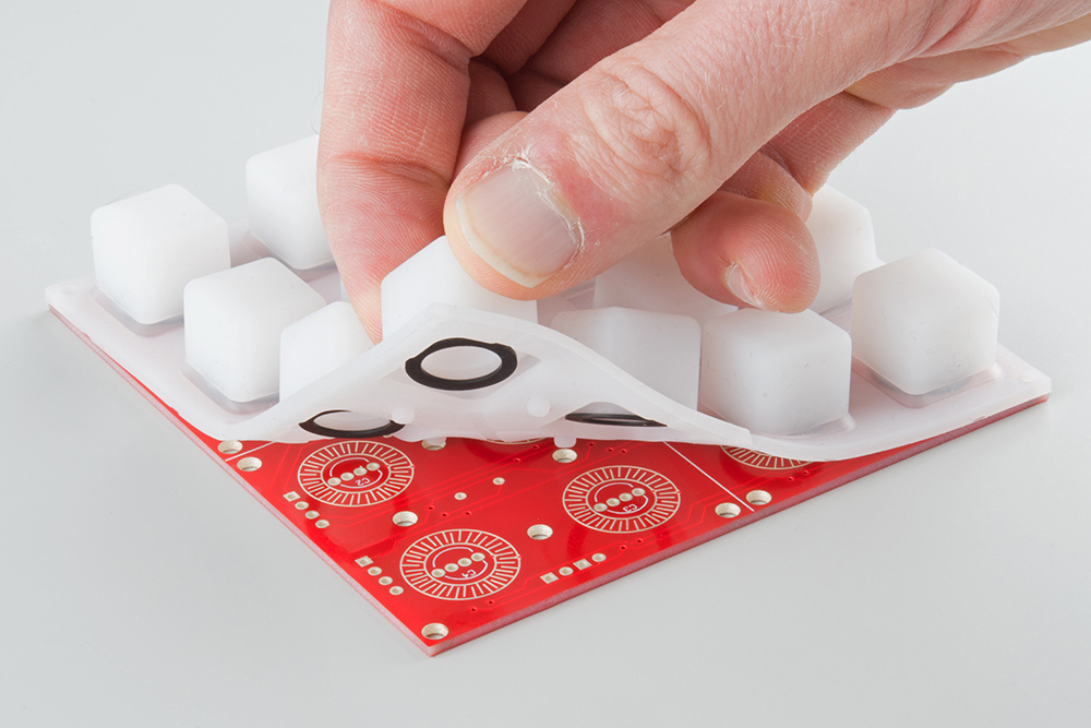
As we saw in the last section, the rubber button pad needs to sit on the PCB to work properly. If anything sticks up too far, the pad won't sit properly, and the buttons will be hard to press.
To keep the components appropriately short, we'll take a little extra care as we install them.
Diodes
The 1n4148 diodes are installed on the back of the PCB, and would usually be soldered on the back of the board. However, since the resulting solder fillets would stick up too far, we'll actually trim them short, and then solder them from the back side of the PCB. It's a bit more work, but the end result is worth the effort.
There are 16 diodes. The diode locations on the PCB are simply marked with a rectangular outline, with a extra stripe at the cathode end.
To install the diodes, first, bend the leads of the diode to fit the holes in the PCB.
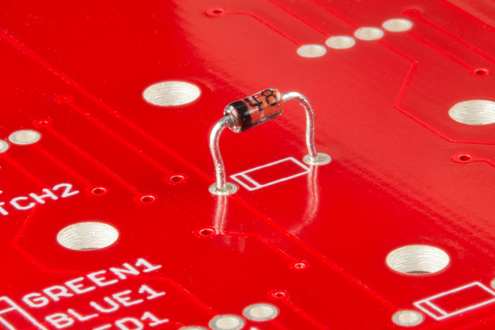
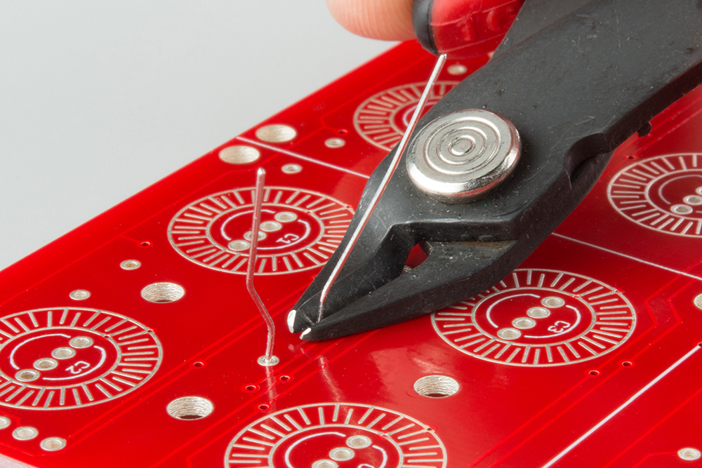
Push the diode down until the body touches the PCB, but don't solder it in. Instead, flip the board over and trim the leads flush.
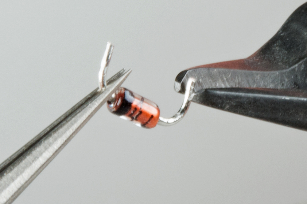
Then remove the trimmed diode, and snip a tiny bit more off the leads. We want to have enough lead left to fit into the hole on the PCB, but not so much that it protrudes.
Finally, put the diode back in the footprint, taking care to keep the cathode stripe pointed the correct direction, matching the silkscreen. Solder it in by tacking the remaining lead, adjacent to the diode body.
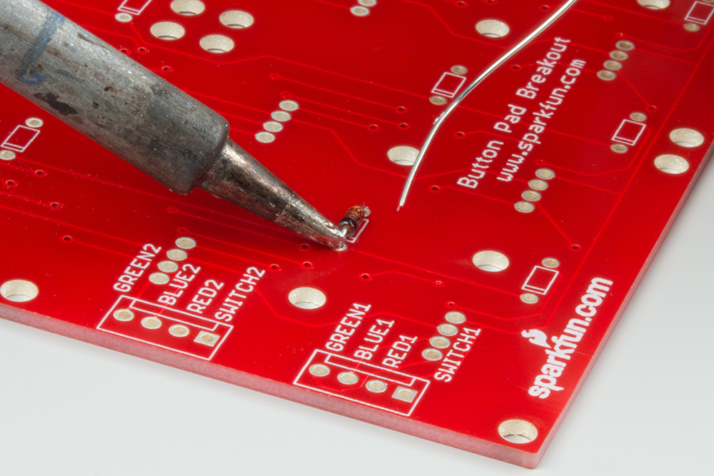
Before moving on, double-check that solder hasn't flowed through the hole, making a bump on the top of the PCB. If it has, you can cut it away with your flush cutters, or remove the bump with a bit of solder wick.
LEDs
Each RGB LED has four leads. The anode of each color has its own pin, and they share a common cathode. The cathode is the longest pin of the bunch.
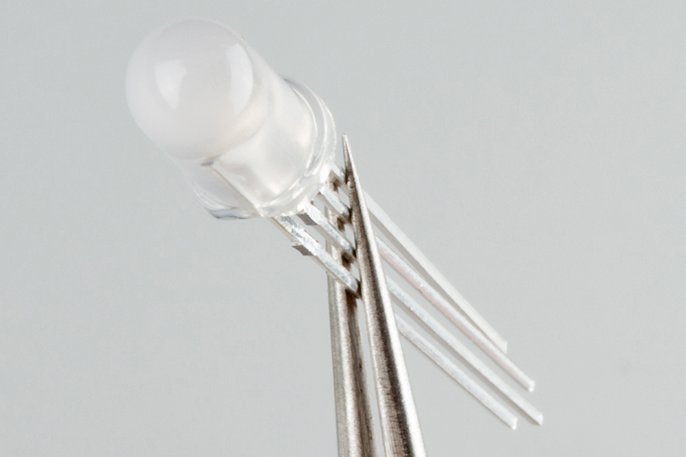
The LEDs are polarized. The body has a small flat edge at the base, that corresponds to the flat on the PCB silkscreen
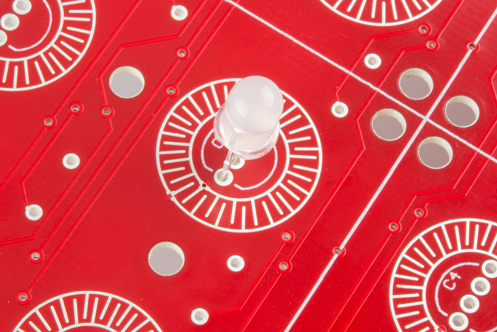
To put the LED on the PCB, insert the diode into the footprint. The longest lead is the second hole in from the flat, the other leads are each a bit shorter. With practice, you can insert the LED by "walking" it from side to side, and each lead will fall into place.
We need to cinch the LED up close to the PCB, to ensure that it will fit inside the recess in the button. If you're unsure about how tall it can be, you can test the fit with the keypad over the LED.
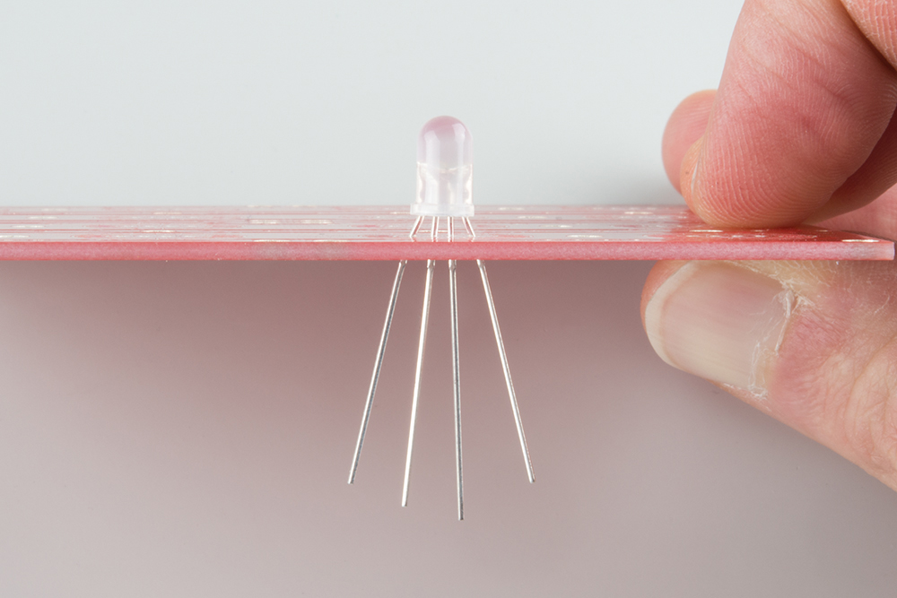
Before soldering, doublecheck the alignment of the flat side of the LED. When you're sure it's the right way around, solder it down, and snip the leads.
Wires
For the following exercises, we'll simply be using solid-core wire to connect the keypad to the Arduino Mega. If you've got a different application in mind, removable connectors or snappable headers might be more suitable. However you chose to connect the button pad, the goal should be to keep the connectors from protruding through the PCB, interfering with the rubber buttons
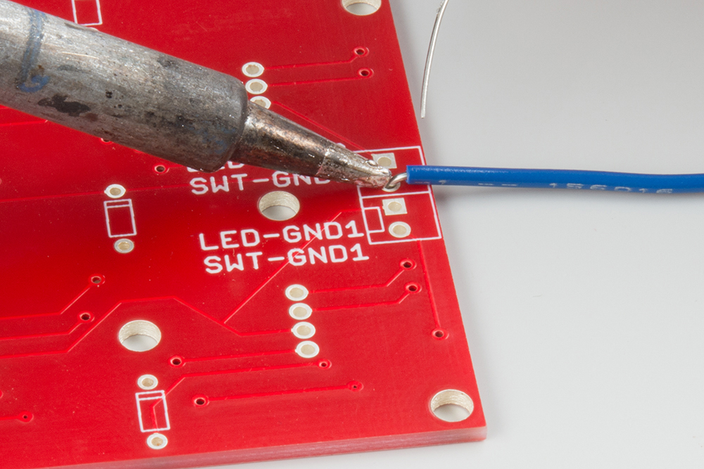
A fully populated 4x4 RGB button pad requires 24 wires to connect it to the microcontroller. We'll install the wires incrementally in the following sections, but each one will be installed using the same basic method. Like the 1N4148 diodes, we'll be soldering them from the back of the PCB, so they don't protrude and create bumps under the keypad.
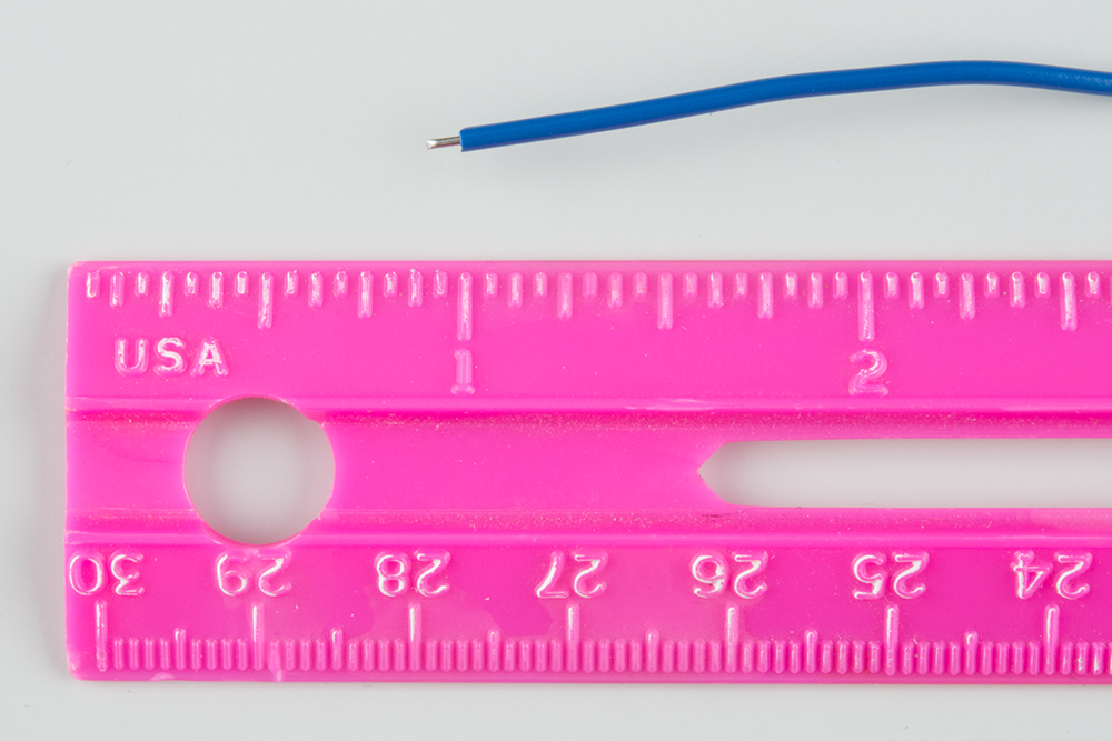
The exercises in this guide were done on a workbench, with the button pad sitting adjacent to the Mega. For that application, each wire was about 6" (15 cm) long.
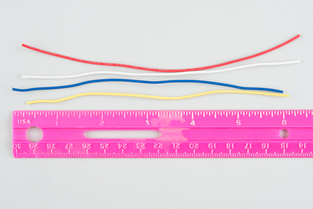
The PCB end of the wire was stripped to reveal about 0.1" of copper.
That end was bent into a gentle curve, and soldered to the PCB. Like the diodes, it was soldered from the back, and anything protruding on the button-side on the board was trimmed flush.
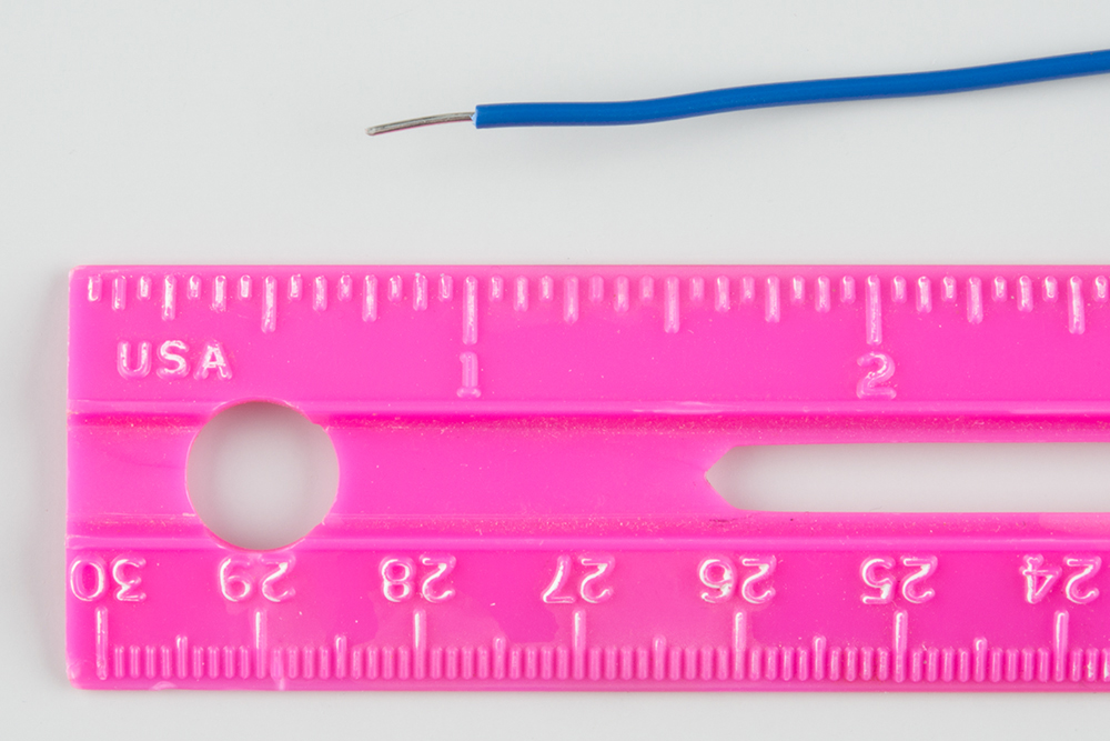
The other end was stripped about 0.25", so it could be inserted into the headers on the Mega.
Final Assembly
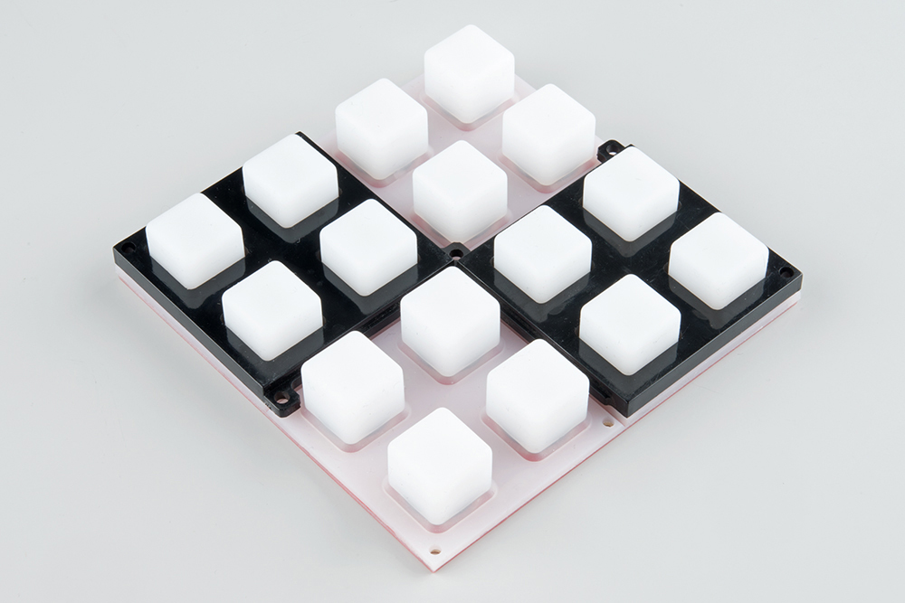
The last assembly step is to place the buttonpad over the PCB...
...and secure it with the plastic bezels. Start with the "bottom" bezels (the ones with the protruding tabs), on opposite corners.
Then add the "top" bezels on the remaining corners.

Finally, insert the Philips screws, and thread them into the standoffs.

Take care to not overtighten the screws. We want to hold the button pad in place, but not tighten it so much that it gets damaged.