Button Pad Hookup Guide
Contributors:
 Byron J.
Byron J. 
The 4x4 RGB Button Pad
With the basics of matrix scanning established, let's look at how they work out in the SparkFun 4x4 RGB Button Pad.
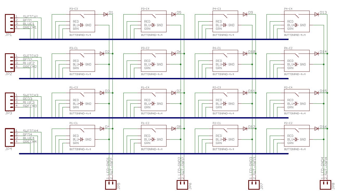
From what we explored in the previous section, we recognize the columns and rows. Each junction in the matrix consists of a pushbutton switch and RGB LED. The LEDs are a single envelope containing separate red, green and blue LEDs, which share a common cathode. The LEDs are set up as three overlapping 4x4 matrices, one for each color.
Errata
The Button pad PCB design dates from around 2008, relatively early in SFE history. As such, it's not completely up to our modern standards for labeling marking and labeling. Let's clarify a few points.
- First, the RGB LED that the PCB was designed for is no longer available. We stock a nearly-equivalent one, but there's one catch -- the Green and Blue pins have traded places.
- The PCB silkscreen has component designators for the LEDs printed on top, but they are marked as C1 to C4. The C (usually used for capacitors) should actually be a D (for diode).
- The row signals are combined into busses (the horizontal dark blue lines). This is a schematic shorthand that results in a simpler schematic, but can make it harder to follow individual wires around the page. In this case, four signals enter the bus on the left and are pulled out at each junction in the matrix.
- The connections at the bottom are marked "ground". These would more accurately be labeled "column".
- For the buttons, they could be marked column select.
- For the LEDs, they are the LED cathodes.
- Rows and columns are both labeled numerically (1 through 4), while it might be easier to understand if one axis were alphabetical, A through D.
Let's assemble our keypad, and start working with it.