Button Pad Hookup Guide
 Byron J.
Background
Even if you're just getting into the world of microcontrollers and embedded programming, you've probably hooked some buttons and LEDs up to your system, and written programs that let you turn the LEDs on and off using the buttons. It's fun to make an LED light up, and even more fun to have a switch that turns it on and off.
Exercises #3, #4, and #5 in the SIK Experiment Guide are versions of exactly that. In those experiments, a variety of LEDs and buttons are attached to a RedBoard, usually with one pin attached to a single button or LED.
If a couple switches and LEDs are fun, then heaps of LEDs and buttons are even better, right?
It naturally leads to questions about the limits of button and LED attachment. If a RedBoard allows 20 pins for digital I/O (digital pins 0-13, and repurposing A0 through A5 as digital), that allows a mix of buttons and LEDs totaling 20 units to be connected. This device-directly-to-pin connection strategy also assumes that we don't need to use pins for other purposes, such as serial communication.
That's a pretty serious constraint for many applications.
A Classic Example
Let's look at a classic microcontroller system with a stylish "buttons & LEDs" user interface, the Roland TR-808 drum machine.
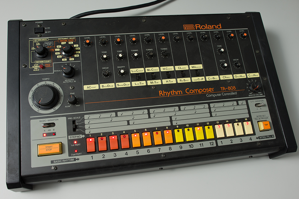
Across the lower edge of the control panel are 16 pushbutton switches, each with a captive red LED. The machine uses the LEDs to indicate its current status, and pressing a button causes the associated LED to toggle on and off.
The 808 was introduced in 1980. The NEC μPD650C microprocessor inside was state of the art for its day, running at 500 KHz (a screaming half megahertz!). It had nine 4-bit wide ports for I/O, but a number of those ports were consumed by the external memory bus (accessing the four KB of external RAM), leaving 20 pins for I/O.
But, the designers of the TR-808 connected all 32 of those components using only twelve I/O pins.
How did they do it? Let's look at that section of the schematic.
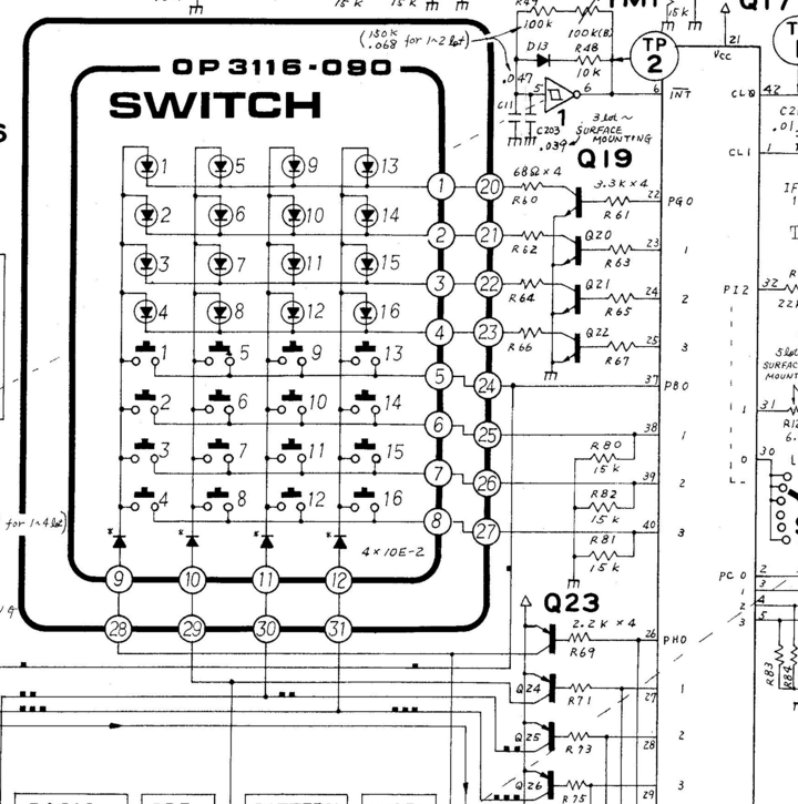
Here you see the LEDs near the top, the buttons below that, and the microcontroller along the left. The LEDs and buttons are in a scan matrix arrangement.
An Introduction To Matrix Scanning.
Matrix scanning is a common technique used to expand the number of inputs or outputs beyond the number of available pins. Matrix scanning requires some cleverness on both the hardware and software sides of the system -- there are some subtle factors at play.
To create a scan matrix, instead of using n pins directly as input or outputs, we allocate them as the axes of a Cartesian coordinate system -- think of them like lines of latitude and longitude. Matrices are usually described using the terms row for an X-axis group, and column for a Y-axis group. Any intersection in the matrix can be described using its X,Y or row, column coordinates.
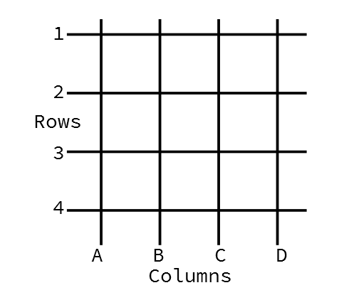
Also keep in mind that the physical layout of a matrix circuit may not correspond to the conceptual axes used in the design. We could lay LEDs out in a circle, but still use X,Y based scanning to address each of them.
The scan matrix circuit places electronic components at the row, column intersections. By selecting a single row and column at a time, each component can be addressed uniquely.
A Simple Example
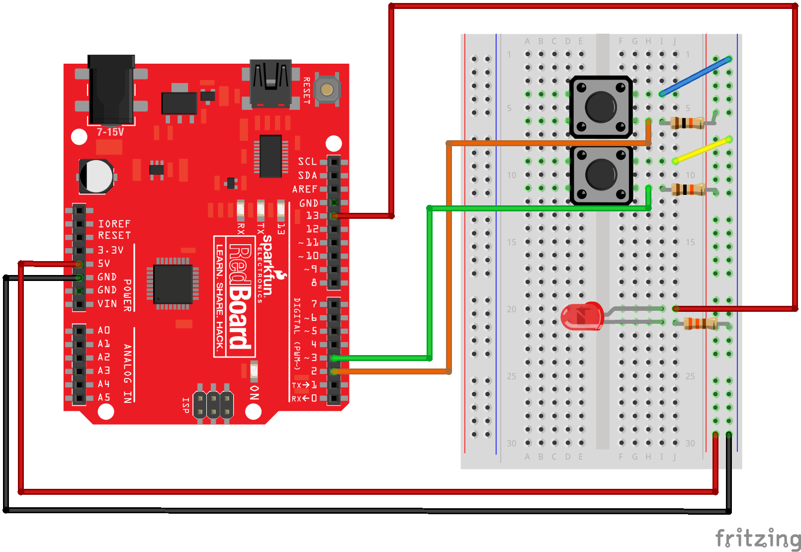
Let's explore a simple example. Using four pins, we'll use two of them as row selectors, and the other two as column selectors. At each intersection in the matrix, we'll install a pushbutton switch that shorts the row to the column.
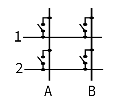
- The row pins are configured as inputs, with pull-up resistors. We'll refer to them as 1 and 2.
- The column pins are configured as outputs. We'll call them A and B.
- At the intersection of each pair of pins, we'll place a momentary-contact switch that bridges the row to the column when it is pressed.
To use this matrix, we drive a single output at a time to select a column. While it's driven, we read the inputs. If we see the drive signal coming back on the input pins, we know that the switch at that X,Y position is closed.
Practical scan matrices often invert the voltages on the pins for a couple of clever reasons. Using inverted logic is called an active low system.
To take advantage of those internal pull-up resistors, scan matrices often use inverted logic. The selected row is set to a low level, and the others are set high. Reading the columns, we look for a logic low to indicate that a button is closed, allowing the selection signal through. This is also why we'll use the relative terms "selected" or "driven," rather than the absolute terms "high" and "low."
The scan consists of walking a logic low around the output pins, and looking for that low on the input pins.
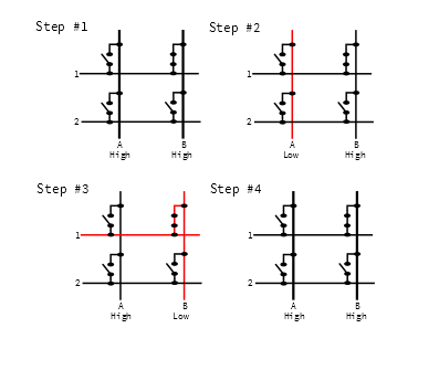
Above, the button at B1 is held. As the scan progresses, it does the following:
- Nothing is selected. Outputs A and B are both high, and we don't worry about inputs 1 and 2.
- Column A is selected with a logical low.
- The system reads inputs 1 and 2. Both are open, so the pull-up resistors cause the inputs to be pulled high. Since this is an active low matrix, the high inputs indicate nothing is pressed.
- The system deselects column A by driving it high and selects column B is by driving it low.
- The system reads inputs 1 and 2. Since switch B1 is held, the low level from the column selection shows up at input 1.
- By pairing the column output (B) with the detected switch (1), the system knows that switch B1 is pressed.
- Finally, everything is deselected by driving both outputs high.
The Problem With Simple
The process described above works well when a single button is held, but it can be problematic when more than one button is held at a time. Let's look at what happens when we press buttons A1 and B1 together.
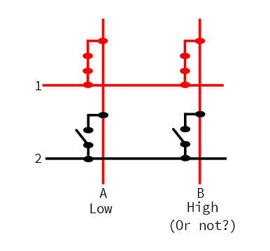
When the scanning sets column output A low, button A1 puts that low voltage onto row 1. Because B1 is also held, the low selection voltage from A is put onto column B, even though B is not selected, and putting a high level on the output pin.
This is a problem!
We have inadvertently connected two outputs together, and driven them to different logic levels. It's hard to predict what the voltage read by input 1 will be. Outputs A and B are contending, and the results depend on the specific architecture of the input and output pins.
- In a perfect universe, the two outputs would balance each other, and the row would sit halfway between the voltages (IE: at 2.5V on a 5V system).
- The universe isn't usually so perfect. It's more likely that one pin can drive harder than the other, and row 1 will be either high or low.
- Sometimes the universe is downright malevolent. By shorting two outputs together, it's possible that the circuitry inside one or both pins could be damaged, and possibly burned out.
Regardless of the actual result, connecting port pins together like this is considered poor practice. Ultimately, the circuit is too simple to be very useful.
A Step Above Simple
To fix the above situation, diodes are put in series with each button, as shown below. The diodes isolate the scan columns from each other, even when multiple buttons are held simultaneously.
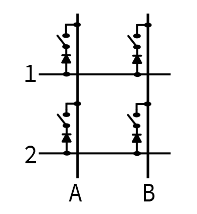
With the diodes in place, and we hold A1 and B1 at the same time, the diode on B1 won't conduct the row voltage back to column B. The short circuit no longer exists, and we can individually detect that A1 and B1 are pressed at the same time.
This circuit is commonly found in MIDI keyboards, where the microcontroller needs to be able to correctly detect that multiple keys are held simultaneously, in order to play chords.
This is also the sort of circuit used in high-quality PC keyboards. Being able to correctly detect arbitrary key combinations is known as N-Key Rollover. While it's not especially useful for everyday touch-typing, it can be very important for gaming, and alternate typing systems, such as braille, and chord typing.
Turning Things Around
We've seen how to scan a 2x2 key matrix for registering input. Now let's turn things around, and use a 2x2 LED matrix for output. The matrix places LEDs at the junctions of the matrix.
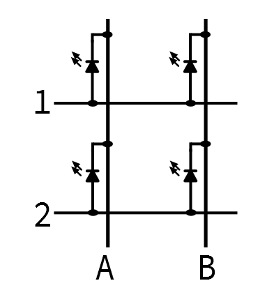
The LED matrix takes advantage of what we discussed in the switch matrix analysis, above -- diodes (or, more specifically, Light Emitting Diodes) only conduct in one direction, when the anode is at a higher voltage than the cathode. If both ends are at the same voltage (both high, or both low), or the diode is reverse biased (anode lower than cathode), then current doesn't flow, and the LED doesn't light up.
Differing from the button examples above, the driving pins are all configured as outputs. By carefully steering voltage onto the columns and rows, we control the voltage across the LEDs, allowing us to address each LED individually.
Let's look at how an active low scan would proceed if we want to light up B1, while leaving the other diodes dark.
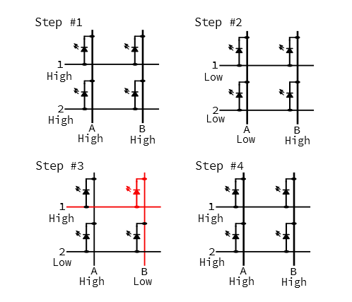
- At the start of the scan, all pins are high.
- The first column is selected by driving pin A low. We don't want the LEDs in column A to light, so we also drive pins 1 and 2 low. There is no voltage across the LEDs, which are therefore dark.
- Column A is deselected be driving it high, and Column B is selected by driving it low. To get LED B1 to light, we also drive row 1 high. B1 is forward biased, and illuminates.
- At the end of the scan, column B is deselected, and rows 1 and 2 are also driven high.
The LED is only illuminated while column B is being scanned. This takes advantage of how our eyes perceive the world around us -- when an LED flashes on and off quickly enough, we see it as being solidly illuminated (although it may appear to be less bright than a continuously lit LED.). This is one example of the phenomenon of persistence of vision.
Growing larger
To address more buttons or LEDs, we simply add columns and rows. For instance, if we wanted 16 buttons , we could add two rows and two columns, making a 4x4 matrix.
A 4x4 matrix almost brings us full circle, back to the Roland TR-808, with its 16 buttons and 16 LEDs. By including both buttons and LEDs, the 808 hits one last design optimization: the scan outputs for the switches are shared with the LEDs.
If we look a little more closely at the schematic, we see (from top to bottom)
- Port G pins 0 through 3 are the LED row select inputs.
- Port B pins 0 through 3 are the switch row inputs.
- Port H pins 0 through 3 are the column outputs, common to both the switches and LEDs.
The output pins in ports G and H are buffered using discrete transistors, since the port pins of the μPD650C aren't capable of sourcing or sinking the current required to get the LEDs to light up.
Port B has discrete pull-down resistors, an indication that this is an active-high scan matrix. The μPD650C doesn't have internal pull-ups, so there's no reason to invert the scan just to take advantage of them.
You'll also notice that instead of a diode per button, the column select lines each have a single diode -- this isolates the column selection outputs, but doesn't prevent misleading behavior if multiple switches are held simultaneously (although such presses can be detected and ignored in software).
A Few More Details
We mentioned above that the scan matrix requires cleverness in both the hardware and software. Our discussion above has covered some of the clever hardware design issues, such as installing diodes to prevent contention, using active-low logic to take advantage of the internal pull-ups on port pins, and sharing select lines between the button and LED matrices.
There are a handful of other issues that a scanned matrix need to take into account, often handled by the associated software.
- The rate at which the scan progresses is a key parameter. When the scan is too slow, the LEDs will visibly flicker, and the buttons will seem unresponsive.
- A faster scan smooths out the LEDs, but becomes susceptible to detecting small glitches in the button actuation. We'll explore software techniques for removing button glitches when we hook up the buttons.
With the basic concepts of matrix scanning covered, lets look at how they're implemented in the 4x4 RGB Button Pad!