Button Pad Hookup Guide
 Byron J.
Exercise #1: Monochrome LEDs
Our first exercise is to get the red LED scan working.
Wiring
To start out, we need to wire up the parts of the matrix that hit the red LEDs -- the LED columns and the red LED row pins.
To make it easier to think about, set the button pad so that the button side is facing you, and connectors are on the left and bottom edges.
This keeps the rows and columns in a fairly sensible order and orientation. The columns are the connections across the bottom, and the rows are the connections up the left edge.
For 16 LEDs in a 4x4 matrix, that makes 4 rows + 4 columns = 8 connections total. These 8 connections are detailed in the following table.
| Function | Color | Button Pad Connection | Mega Connection |
| Red LED Row 1 | Red | Red1 | 22 |
| Red LED Row 2 | Red | Red2 | 30 |
| Red LED Row 3 | Red | Red3 | 33 |
| Red LED Row 4 | Red | Red4 | 36 |
| LED Column A | Green | LED-GND-4 | 42 |
| LED Column B | Yellow | LED-GND-3 | 43 |
| LED Column C | Blue | LED-GND-2 | 44 |
| LED Column D | White | LED-GND-1 | 45 |
You'll notice that the column selects are on adjacent pins, but the red LED rows are spaced apart -- this leaves the interceding pins for the corresponding green and blue connections.
With the wires attached to the PCB, it will look like this:
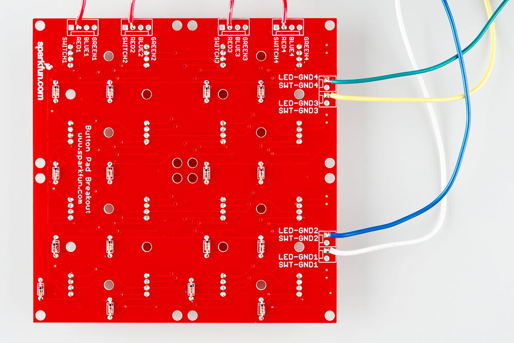
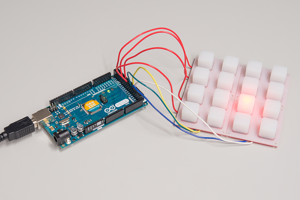
Each wire was prepared and soldered as described in the assembly section, and the end was stuck into the header on the Mega.
Code
The following sketch illuminates a single red LED at a time. The illuminated LED walks around the matrix.
language:c

/******************************************************************************
red-only.ino
Byron Jacquot @ SparkFun Electronics
1/6/2015

Example to drive the red LEDs in the RGB button pad.

Exercise 1 in a series of 3.
https://learn.sparkfun.com/tutorials/button-pad-hookup-guide/exercise-1-monochrome-leds

Development environment specifics:
Developed in Arduino 1.6.5
For an Arduino Mega 2560

This code is released under the [MIT License](http://opensource.org/licenses/MIT).

Distributed as-is; no warranty is given.
******************************************************************************/
//config variables
#define NUM_LED_COLUMNS (4)
#define NUM_LED_ROWS (4)
#define NUM_COLORS (1)

// Global variables
static bool LED_buffer[NUM_LED_COLUMNS][NUM_LED_ROWS];
static int32_t next_advance;
static uint8_t led_index;

static const uint8_t ledcolumnpins[NUM_LED_COLUMNS]   = {42,43,44,45};
static const uint8_t colorpins[NUM_LED_ROWS] = {22,30,33,36};

static void setuppins()
{
  uint8_t i;

  // initialize all of the output pins

  // LED column lines
  for(i = 0; i < NUM_LED_COLUMNS; i++)
  {
    pinMode(ledcolumnpins[i], OUTPUT);

    // with nothing selected by default
    digitalWrite(ledcolumnpins[i], HIGH);
  }

  // LED row lines
  for(i = 0; i < NUM_LED_ROWS; i++)
  {
    pinMode(colorpins[i], OUTPUT);

    // with nothing driven by default
    digitalWrite(colorpins[i], LOW);
  }

}

static void scan()
{
  static uint8_t current = 0;
  uint8_t val;
  uint8_t i, j;

  // Select a column
  digitalWrite(ledcolumnpins[current], LOW);

  // write the row pins
  for(i = 0; i < NUM_LED_ROWS; i++)
  {
    if(LED_buffer[current][i])
    {
      digitalWrite(colorpins[i], HIGH);
    }
  }

  delay(1);

  digitalWrite(ledcolumnpins[current], HIGH);

  for(i = 0; i < NUM_LED_ROWS; i++)
  {
    digitalWrite(colorpins[i], LOW);
  }

  // Move on to the next column
  current++;
  if (current >= NUM_LED_COLUMNS)
  {
    current = 0;
  }

}

void setup()
{
  // put your setup code here, to run once:
  Serial.begin(115200);
  Serial.print("Starting Setup...");

  // setup hardware
  setuppins();

  // init global variables
  next_advance = millis() + 1000;
  led_index = 0;

  // Initialize the LED display array
  for(uint8_t i = 0; i < NUM_LED_COLUMNS; i++)
  {
    for(uint8_t j = 0; j < NUM_LED_ROWS; j++)
    {
      LED_buffer[i][j] = false;
    }
  }
  // Set the first LED in the buffer on
  LED_buffer[0][0] = true;

  Serial.println("Setup Complete.");

}

void loop()
{
  // put your main code here, to run repeatedly:

  scan();

  if(millis() >= next_advance)
  {
    next_advance = millis()+1000;

    LED_buffer[led_index/NUM_LED_COLUMNS][led_index%NUM_LED_COLUMNS] = false;
    led_index++;
    led_index %= (NUM_LED_COLUMNS * NUM_LED_ROWS);
    LED_buffer[led_index/NUM_LED_COLUMNS][led_index%NUM_LED_COLUMNS] = true;
  }
}
The code is an implementation if what we described in the background section. A column is selected, and the corresponding row pins are driven to get the LEDs to light.
Let's look at a few of the finer points in the code.
- In an effort to make the code more portable and configurable, the basic parameters are defined in a set of definitions at the top of the sketch.
- The image displayed by the LEDs is declared as a two-dimensional array of
bool. The array dimensions match the rows and columns. - The pins themselves are defined as constant one-dimensional arrays. This makes it easy to:
- Reassign the pins, by simply editing the array initialization values.
- Walk from pin to pin, by incrementally indexing the array.
- The matrix scan is performed by the
scan()function.- On each invocation, the scan selects the next column, then writes the corresponding row pins with the values from the LED array.
- It pauses for a millisecond, which allows the LED to glow for a moment.
- If you're curious, remove this
delay(1), and you'll find that the LEDs get significantly dimmer.
- If you're curious, remove this
- Then it deselects the column and stops driving the rows.
loop()calls the scan function every time it is invoked. Because it contains thedelay(1)mentioned above, the scan updates at most once every millisecond.- Every second (or 1000
millis()), the loop walks the illuminated LED to the next position.
The next exercise is to add button inputs to this, allowing you to turn each LED on or off by pressing the corresponding button.