Button Pad Hookup Guide
Materials
The following exercises use the items on the following wishlist.
Tools
You'll also need to following tools.
Before we assemble the button pad, let's take a closer look at some of the parts.
The PCB
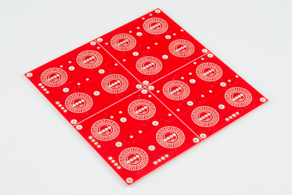
The PCB is designed with geometric features that interface with the button pad. The most obvious are the circular traces printed on top, with interlocking fingers that are bridged by the rings in the keypad, completing the button circuit.
Inside each set of circles is the footprint for a common-cathode RGB LED.
The Button Pad
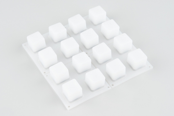
The 4x4 Rubber Keypad is molded from Dow Corning Silastictm Silicone rubber. It's similar to the keypads used by television remote controls.
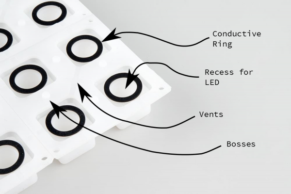
If we flip it over, we'll see a some particular details molded into the rubber.
There are several features on the back of the button pad worth noting.
- Contact rings -- The most important feature is probably the conductive ring molded into the back of each button. It makes contact with fingers on the printed circuit board.
- Recesses -- Each button also has a hollow cavity in it, leaving room for a 3mm or 5mm PTH LED.
- Vents -- There are little troughs in the rubber that allow air to escape when the button is pressed. This make it easier to press the buttons, and prevents them from suctioning onto the PCB.
- Bosses -- These are little pegs that interface with holes in the PCB, to keep the keypad from sliding around.
The Bezels
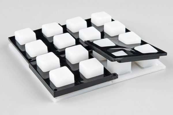
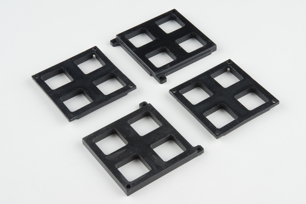
When the keypad is placed on the PCB, it is held in place by a set of brackets known as the "bezel."
There are actually four bezels in the wish list, two marked "bottom," and two marked "top." These designators indicate the positions the the bezels get installed in. The bottom bezels have tabs that stick out, and the top bezels have recesses those tabs fit into.
