Button Pad Hookup Guide
 Byron J.
Exercise #2: Monochrome plus Buttons
Our Second exercise is to add the buttons to the scan matrix. We'll use them as inputs, to toggle the corresponding LEDs on and off.
We're going to assume that you're following this guide in order, and have just completed exercise #1. This exercise will describe the additions needed to add the button matrix, building incrementally on top of exercise #1.
Wiring
We're going to add another 8 wires to interface the button matrix. This breaks down as four button columns and four button rows, and described in the following table.
| Function | Wire Color | Button Pad Connection | Mega Connection |
| Button Row 1 | Black | Switch1 | 46 |
| Button Row 2 | Yellow | Switch2 | 47 |
| Button Row 3 | Green | Switch3 | 48 |
| Button Row 4 | Blue | Switch4 | 49 |
| Button Column A | Green | SWT-GND-4 | 50 |
| Button Column B | Yellow | SWT-GND-3 | 51 |
| Button Column C | Blue | SWT-GND-2 | 52 |
| Button Column D | White | SWT-GND-1 | 53 |
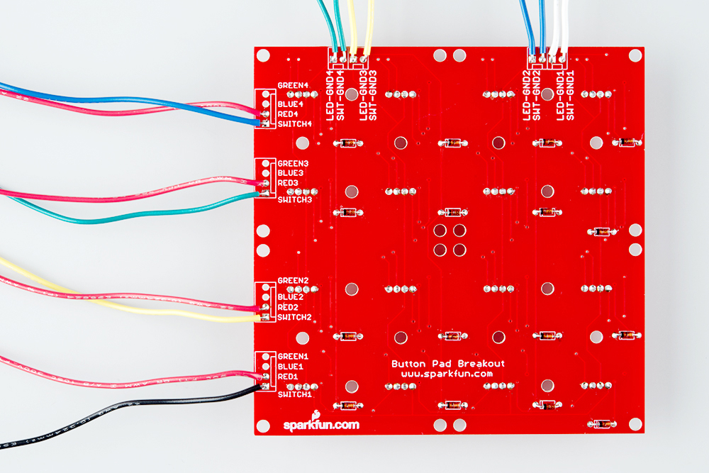
Again, the wires are prepared and soldered as described in the assembly section, and the other end is stuck into the header on the Mega. With these wires, we're adding column and row connections for the buttons. When they're in place, the connections to the PCB look like this.
Code
The following sketch adds button support to the previous sketch.
language:c
/******************************************************************************
red-plus-buttons.ino
Byron Jacquot @ SparkFun Electronics
1/6/2015

Example to drive the red LEDs and scan the buttons of the RGB button pad.

Exercise 2 in a series of 3.
https://learn.sparkfun.com/tutorials/button-pad-hookup-guide/exercise-2-monochrome-plus-buttons

Development environment specifics:
Developed in Arduino 1.6.5
For an Arduino Mega 2560

This code is released under the [MIT License](http://opensource.org/licenses/MIT).

Distributed as-is; no warranty is given.
******************************************************************************/
//config variables
#define NUM_LED_COLUMNS (4)
#define NUM_LED_ROWS (4)
#define NUM_BTN_COLUMNS (4)
#define NUM_BTN_ROWS (4)
#define NUM_COLORS (1)

#define MAX_DEBOUNCE (3)

// Global variables
static bool LED_buffer[NUM_LED_COLUMNS][NUM_LED_ROWS];

static const uint8_t btncolumnpins[NUM_BTN_COLUMNS] = {50, 51, 52, 53};
static const uint8_t btnrowpins[NUM_BTN_ROWS]       = {46, 47, 48, 49};
static const uint8_t ledcolumnpins[NUM_LED_COLUMNS] = {42, 43, 44, 45};
static const uint8_t colorpins[NUM_LED_ROWS]        = {22, 30, 33, 36};

static int8_t debounce_count[NUM_BTN_COLUMNS][NUM_BTN_ROWS];

static void setuppins()
{
  uint8_t i;

  // initialize
  // select lines
  // LED columns
  for (i = 0; i < NUM_LED_COLUMNS; i++)
  {
    pinMode(ledcolumnpins[i], OUTPUT);

    // with nothing selected by default
    digitalWrite(ledcolumnpins[i], HIGH);
  }

  // button columns
  for (i = 0; i < NUM_BTN_COLUMNS; i++)
  {
    pinMode(btncolumnpins[i], OUTPUT);

    // with nothing selected by default
    digitalWrite(btncolumnpins[i], HIGH);
  }

  // button row input lines
  for (i = 0; i < NUM_BTN_ROWS; i++)
  {
    pinMode(btnrowpins[i], INPUT_PULLUP);
  }

  // LED drive lines
  for (i = 0; i < NUM_LED_ROWS; i++)
  {
    pinMode(colorpins[i], OUTPUT);
    digitalWrite(colorpins[i], LOW);
  }

  // Initialize the debounce counter array
  for (uint8_t i = 0; i < NUM_BTN_COLUMNS; i++)
  {
    for (uint8_t j = 0; j < NUM_BTN_ROWS; j++)
    {
      debounce_count[i][j] = 0;
    }
  }
}

static void scan()
{
  static uint8_t current = 0;
  uint8_t val;
  uint8_t i, j;

  // Select current columns
  digitalWrite(btncolumnpins[current], LOW);
  digitalWrite(ledcolumnpins[current], LOW);

  // output LED row values
  for (i = 0; i < NUM_LED_ROWS; i++)
  {
    if (LED_buffer[current][i])
    {
      digitalWrite(colorpins[i], HIGH);
    }
  }

  // pause a moment
  delay(1);

  // Read the button inputs
  for ( j = 0; j < NUM_BTN_ROWS; j++)
  {
    val = digitalRead(btnrowpins[j]);

    if (val == LOW)
    {
      // active low: val is low when btn is pressed
      if ( debounce_count[current][j] < MAX_DEBOUNCE)
      {
        debounce_count[current][j]++;
        if ( debounce_count[current][j] == MAX_DEBOUNCE )
        {
          Serial.print("Key Down ");
          Serial.println((current * NUM_BTN_ROWS) + j);

          // Do whatever you want to with the button press here:
          // toggle the current LED state
          LED_buffer[current][j] = !LED_buffer[current][j];
        }
      }
    }
    else
    {
      // otherwise, button is released
      if ( debounce_count[current][j] > 0)
      {
        debounce_count[current][j]--;
        if ( debounce_count[current][j] == 0 )
        {
          Serial.print("Key Up ");
          Serial.println((current * NUM_BTN_ROWS) + j);

          // If you want to do something when a key is released, do it here:

        }
      }
    }
  }// for j = 0 to 3;

  delay(1);

  digitalWrite(btncolumnpins[current], HIGH);
  digitalWrite(ledcolumnpins[current], HIGH);

  for (i = 0; i < NUM_LED_ROWS; i++)
  {
    digitalWrite(colorpins[i], LOW);
  }

  current++;
  if (current >= NUM_LED_COLUMNS)
  {
    current = 0;
  }

}

void setup()
{
  // put your setup code here, to run once:
  Serial.begin(115200);

  Serial.print("Starting Setup...");

  // setup hardware
  setuppins();

  // init global variables
  for (uint8_t i = 0; i < NUM_LED_COLUMNS; i++)
  {
    for (uint8_t j = 0; j < NUM_LED_ROWS; j++)
    {
      LED_buffer[i][j] = 0;
    }
  }

  Serial.println("Setup Complete.");

}

void loop() {
  // put your main code here, to run repeatedly:

  scan();

}
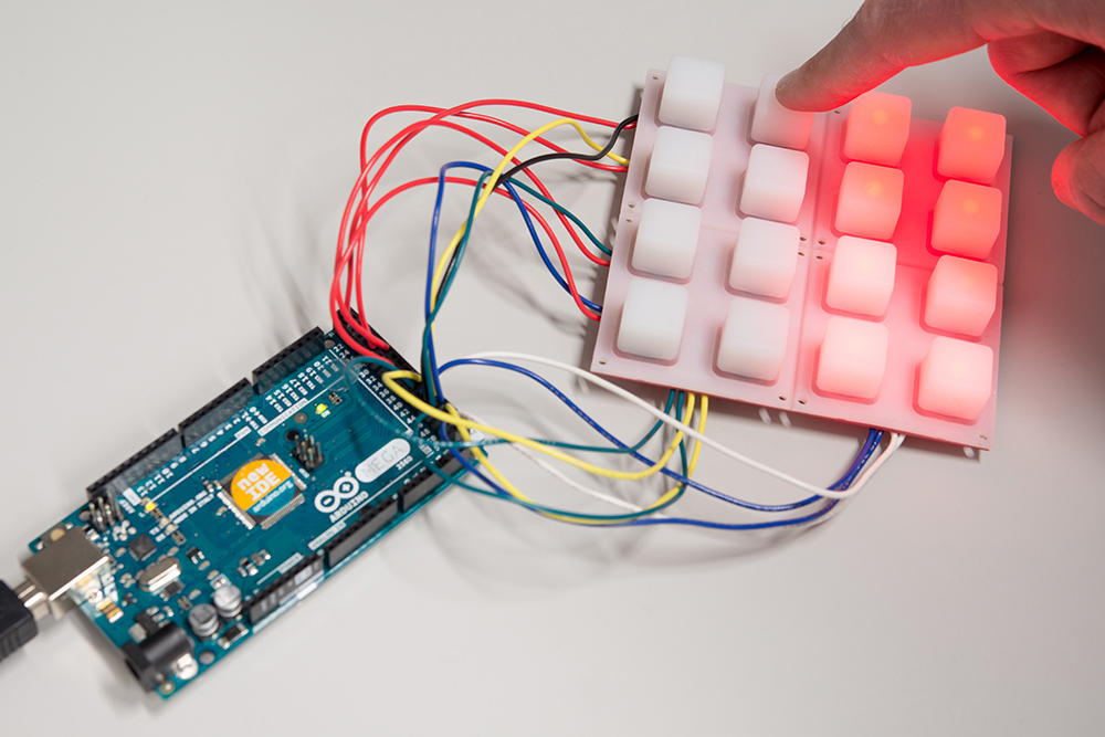
Once the code is loadeed, the keypad doesn't do anything on its own, but when you press a button, the corresponding LED toggles on and off.
The button scan is added in parallel to the LED scan. A column is selected, and a row is read. Some new definitions have been added to dimension the button matrix, plus some new data tables to define the pins for those functions.
The most complex part of this code is the button press detection, which involves a little extra work. When the buttons open or close, sometimes the change isn't especially clean -- the contacts might chatter or bounce when they close. The waveforms below show a couple of different switch actuations, captures from this button pad.
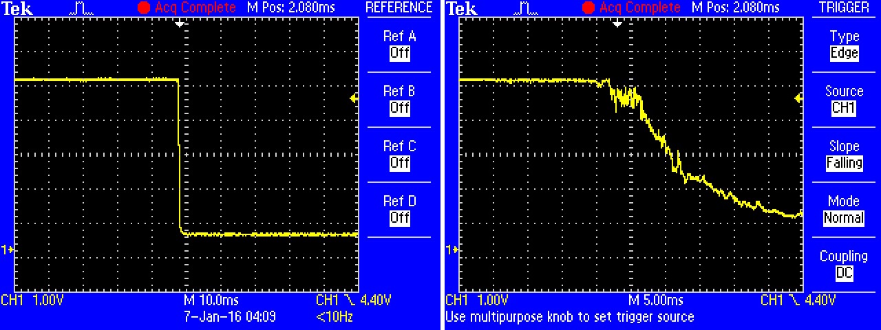
The nice closure on the left was the result of pressing the button quickly and decisively, straight down. The closure on the right is the result of pushing the button slowly, at an oblique angle. The ring inside twisted down onto the fingers of the PCB contacts. In this instance it takes roughly 20 milliseconds for the button to close solidly.
The glitchiness can cause the scanning system to misinterpret the chatter as multiple keypresses, when in fact the button was only actuated once.
To prevent this, the software uses some logic to perform debouncing. The scan system has to find a switch closed for several scans in a row before it decides that the switch is actually closed. It uses the two-dimensional array debounce_count to keep track of the number of successive scans. When a switch is found closed, the counter is incremented. When the counter reaches the constant MAX_DEBOUNCE, it decides that the switch has been solidly and cleanly closed, and acts on the keypress.
When a key is released, the counter counts back down to zero. This example prints a message when it detects a release. Some applications don't take any action on key releases (like the keypad on an ATM), but it's necessary in others (such as MIDI keyboards).
For the rubber button pad, a MAX_DEBOUNCE of 2 or 3 seems to work fairly well. Other types of buttons might require different debounce values.
With the red LEDs and buttons working, the final step is to get the green and blue LEDs working.