Building a Safe Cracking Robot
Contributors:
 Nate
Nate
Nate 
Brains
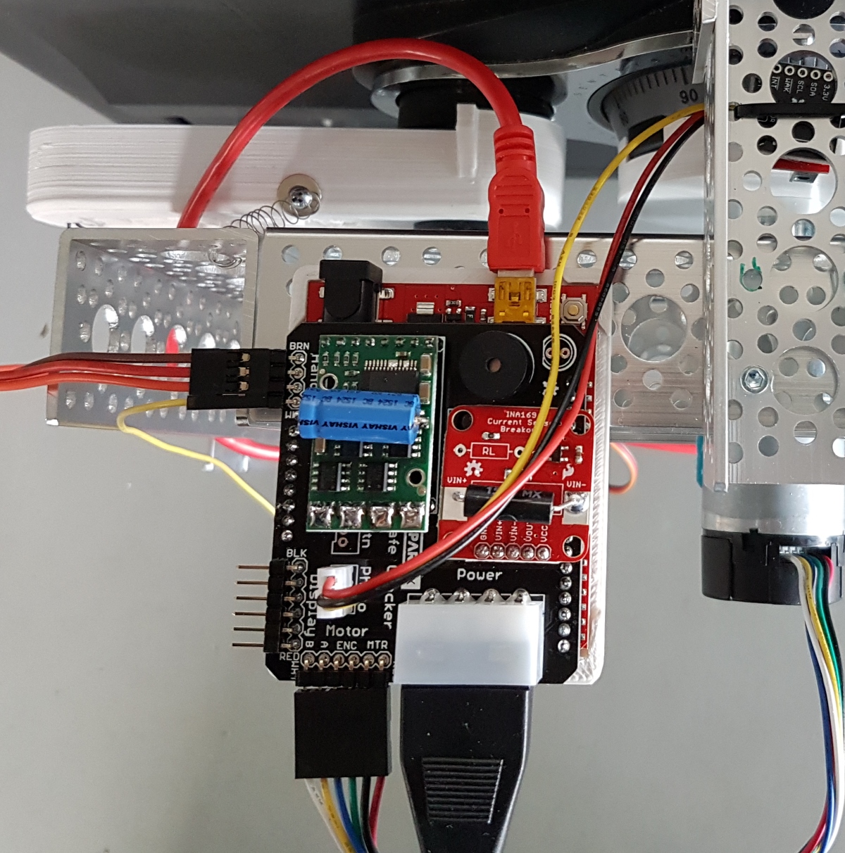
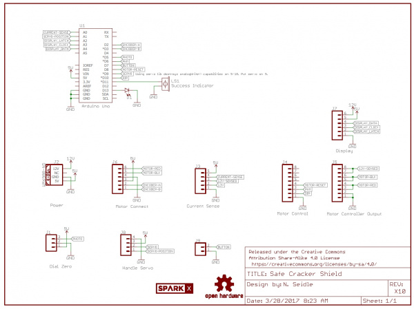
We used the trusty RedBoard to control everything. The Safe Cracker shield is a simple two layer PCB.
Bits on the shield:
- The 12V/5V power supply provides the power to the current sensor and motor controller.
- Current sensor: We originally planned on using the current sensor to detect motor stall when the edge of an indent in disc C was hit. It turned out being much faster and more accurate to detect the indent edge with the encoder; if the encoder had not changed in 5 milliseconds then the motor was stopped and we had hit the edge of the indent.
- Motor controller: 15A was more than enough to handle the motor’s 5A stall current
- Servo connector with feedback
- Photogate connector
- Display connector for the large 6.5” 7-segment display (needed only for our live stream event)
- Buzzer to announce when we’ve cracked it
- ‘GO’ button connector if we wanted to make the apparatus headless
Code
You can find the firmware here. While the code to control the SparkFun Safe Cracker got a bit large, it’s fairly straight forward. In essence, we go to a given dial location, pull on the handle, see if the handle moved far enough that we’re open, repeat. Additionally, we created functions to allow us to measure, as precisely as possible, the widths of the indents on disc C.