Building a Safe Cracking Robot
 Nate
Nate 
Introduction
My wife is amazing; for Christmas this year, she gave me a fire safe she purchased off of Craigslist. It was super cheap because the seller didn’t have the combination. Best present ever.
Step 1) Get a safe that hasn’t been opened.
Step 2) Deploy robot army.
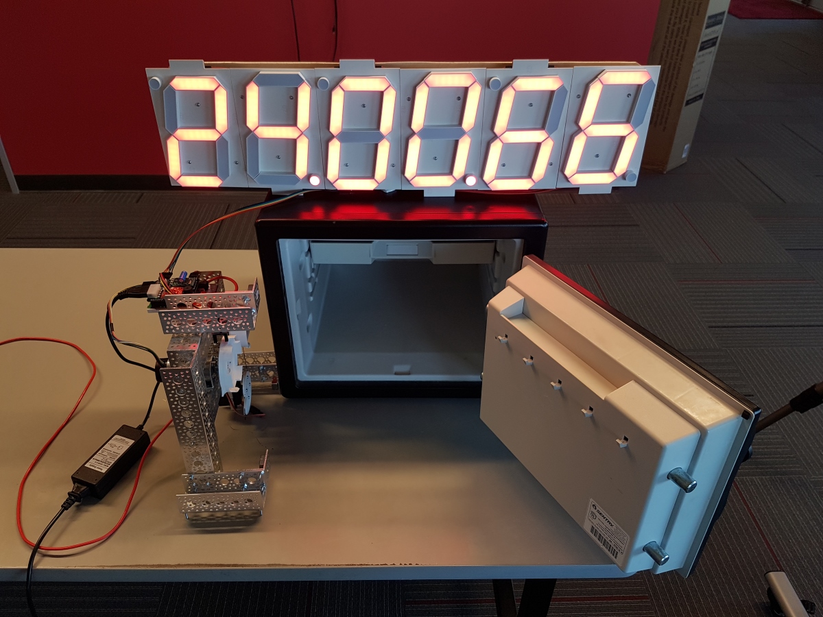
We were able to crack our Craigslist safe in 40 minutes and 42 seconds! You can re-watch the live cracking, if you'd like. The magic moment occurs at 45:20, but start around 44:30 to get the full scope of what's happening.
Brute force robots for combination safes are not new. They are sometimes called an "Autodialer". And, the robots that use audio feedback are sometimes called “SoftDrill”. The SparkFun Safe Cracker is a variant of the Autodialer. Instead of attempting every combination in the solution domain (called brute forcing), we use some tricks to reduce the domain and shortcuts to speed up the testing process. In addition, the SparkFun Safe Cracker is cheap (~$200), magnetically adheres to the safe, and is non-destructive; when we’re done you'll never know we were there.
Isn't this a bad idea?
We believe knowledge and education is the best protection against fear and tyranny. The SparkFun Safe Cracker is designed to open very low security combination fire safes. There are high-end, secure, expensive combination safes available that have the ability to detect and thwart this type of dialer attack. Or, you could use a keypad safe.
Build Your Own!
We’ve documented and shared all the lessons we’ve learned in hopes that you can possibly build your own. You’ll need a 3D printer, soldering iron, and the ability to write code and modify 3D files to fit the type of safe you’re trying to open.
This is a complex build so here’s a list of documents:
- Eagle files for the PCB
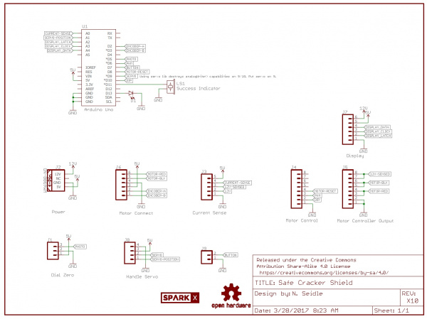
- Schematic
- Arduino based firmware
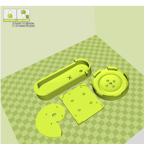
- 3D files for the dial coupler and handle puller
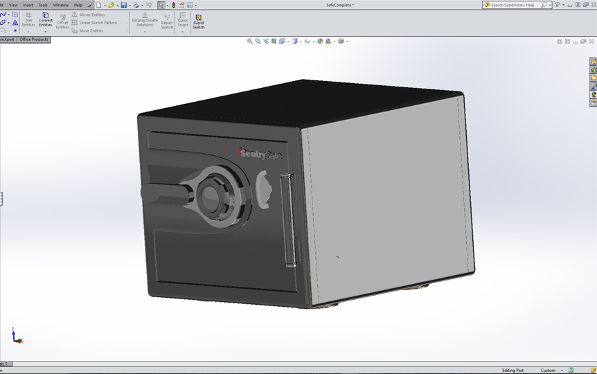
- 3D model of the safe
- SparkFun parts list
- Additional Parts:
- $40 DC gearhead motor
- Three BCA6 magnets worked very well
- Custom PCB (order from your favorite fab house)
All in all, we've spent about $200 on our safe cracker, which is a fraction of what professional devices cost.
For the latest files, check out the repo here.
Dial and Coupler
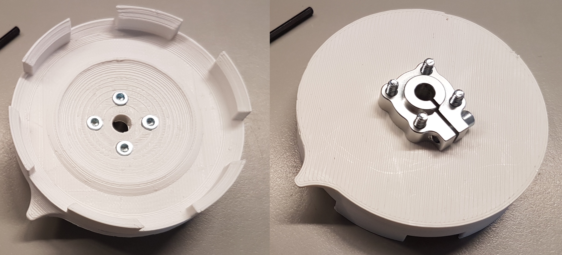
The dial on our safe was modeled, and a coupler was 3D printed. This was attached to our motor with a 6mm clamping hub. We found that hubs with set screws would loosen quickly and wreak havoc with our control algorithms. Use a clamping hub!
We used a motor from Pololu for $40 that has the following specs
- 12V motor
- 350mA Free Run
- 5A stall
- 80RPM
- 8400 counts per revolution
The counts per revolution was most important. We wanted a lower cost motor that had LOTS of resolution to measure the internal indents in disc C (covered in a later section). 12V was good because we had used a similar power supply and display for our Speed Trap project.
The encoder uses two interrupt pins connected to the interrupt pins on the Arduino. Once we zero the dial, the step count is used to determine on which digit the dial is.
Quick example:
100 / 8400 = 84 ticks per digit 3226 steps = dial number 34
It’s worth noting that the tolerances of the coupler to dial and the rigidness of the hub and motor mounts are important. Any slack in the system will cause problems later.
Home Calibration
We tried a few different methods to calibrate the dial. Originally, we tried a reed switch with a magnet built into the 3D printed coupler. This was a horrible idea: reed switches detect relative proximity but are bad at detecting exact location. I had a few instances where the reed switch would open when the magnet was directly under the switch and close again when the magnet moved a few millimeters away. Don’t use a reed switch.
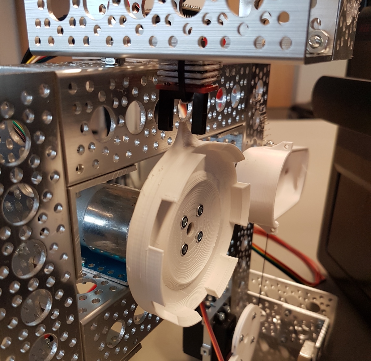
We ended up using a photogate with a small flag designed into the coupler. It’s straightforward to detect when the gate is broken by the flag. When the robot is magnetically attached to the safe, the dial is in an unknown position. There’s an offset variable that can be set so that when you say, "go home", the robot figures out that the flag is at dial position 43, and it needs to travel 57 more to arrive at home.
Once calibrated (and after lots of code revisions), we found that the control of the dial was very reliable. During cracking, we recalibrate every time we adjust disc A just to be safe.
Handle Puller

We tried a few different methods to non-permanently attach to the handle. First, we had to model the safe handle then design and print a connector. It’s basically a shroud with an idler pin to rotate around with a 40 lbs cord attached to the end of the shroud. A small spring is used to bring the shroud and handle back to return position when the servo returns to the rest position. You don’t want to let the handle rest under its own weight or it might fall onto the dials and get caught in the indents on disc C.
We really wanted to use an off-the-shelf servo for cost and ease of use. A basic 83 oz-in servo worked ok, but it didn’t have enough throw to guarantee that it could pull the handle down far enough to the open position. Rob had the breakthrough: using a nautilus design we can apply increasing torque to the handle as the servo head pulls on the string. It works extremely well.
Additionally, we modified our servo to give us analog feedback (there are good tutorials 1 and 2 on how to do this). Analog feedback is important; when you tell the servo head to go to position 175, did it actually get there? Doing an analogRead() lets us know if we’ve arrived.
To detect if the safe is opened, we tell the servo to pull on the handle by going to PWM value 80. If we've dialed in the right combination, the the servo is free to fully pull down and move to this PWM value. The analog value when the handle is pulled down is approximately 273. If the servo gets blocked (wrong combination) the servo’s analog feedback will be less than 250. The tryHandle() function does all this for us and returns true if the analog feedback goes above 260. The PWM and analog values will be different for each robot setup, so we've written a few functions to manually adjust the servo to get the opening conditions.
Brains
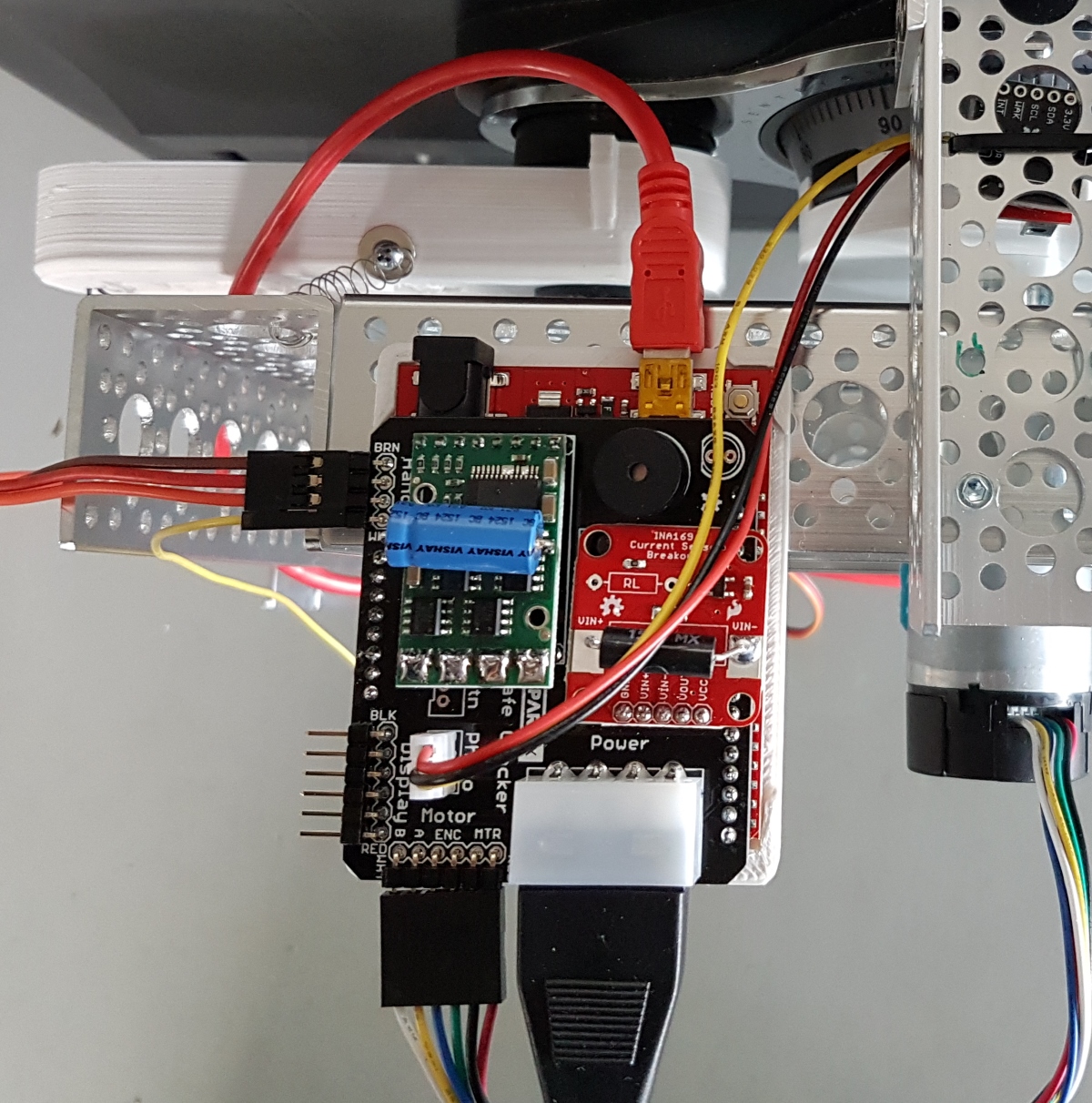
We used the trusty RedBoard to control everything. The Safe Cracker shield is a simple two layer PCB.
Bits on the shield:
- The 12V/5V power supply provides the power to the current sensor and motor controller.
- Current sensor: We originally planned on using the current sensor to detect motor stall when the edge of an indent in disc C was hit. It turned out being much faster and more accurate to detect the indent edge with the encoder; if the encoder had not changed in 5 milliseconds then the motor was stopped and we had hit the edge of the indent.
- Motor controller: 15A was more than enough to handle the motor’s 5A stall current
- Servo connector with feedback
- Photogate connector
- Display connector for the large 6.5” 7-segment display (needed only for our live stream event)
- Buzzer to announce when we’ve cracked it
- ‘GO’ button connector if we wanted to make the apparatus headless
Code
You can find the firmware here. While the code to control the SparkFun Safe Cracker got a bit large, it’s fairly straight forward. In essence, we go to a given dial location, pull on the handle, see if the handle moved far enough that we’re open, repeat. Additionally, we created functions to allow us to measure, as precisely as possible, the widths of the indents on disc C.
Frame
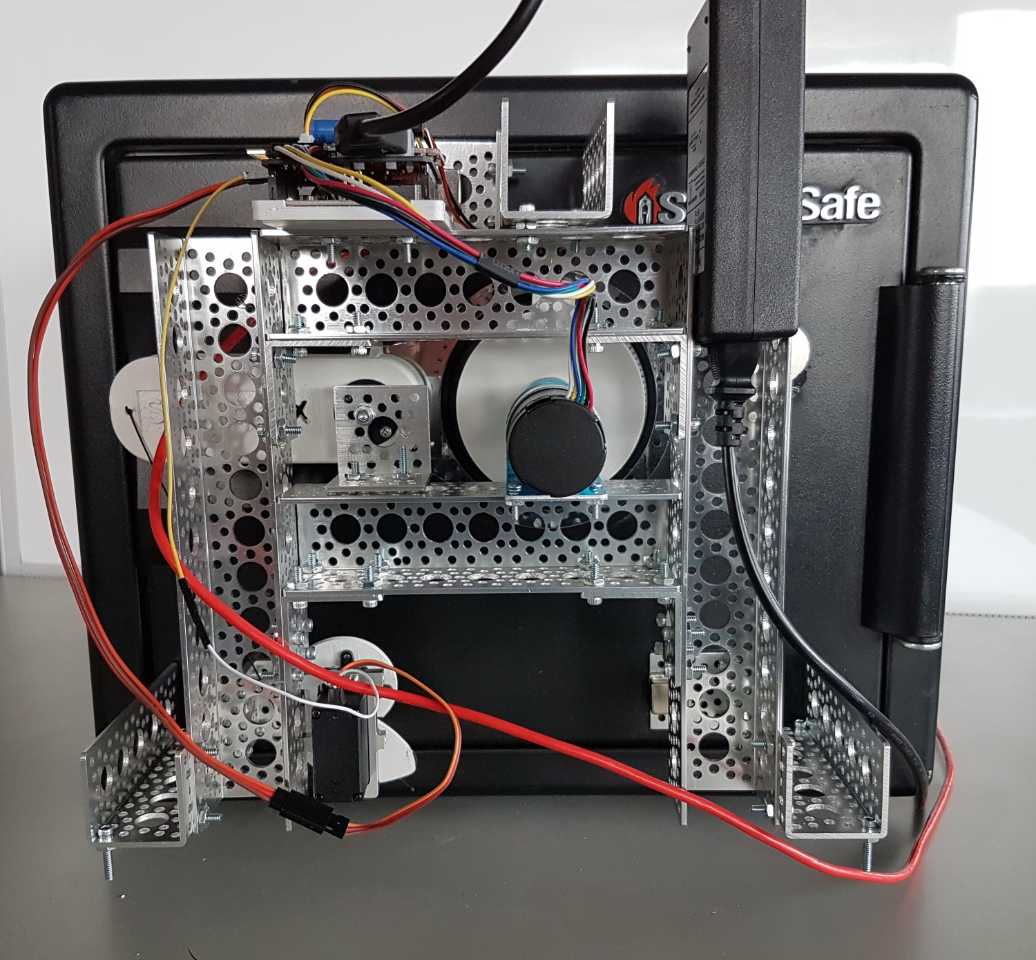
To build an apparatus that could be easily and quickly attached to our safe, we first modeled the safe in 3D.
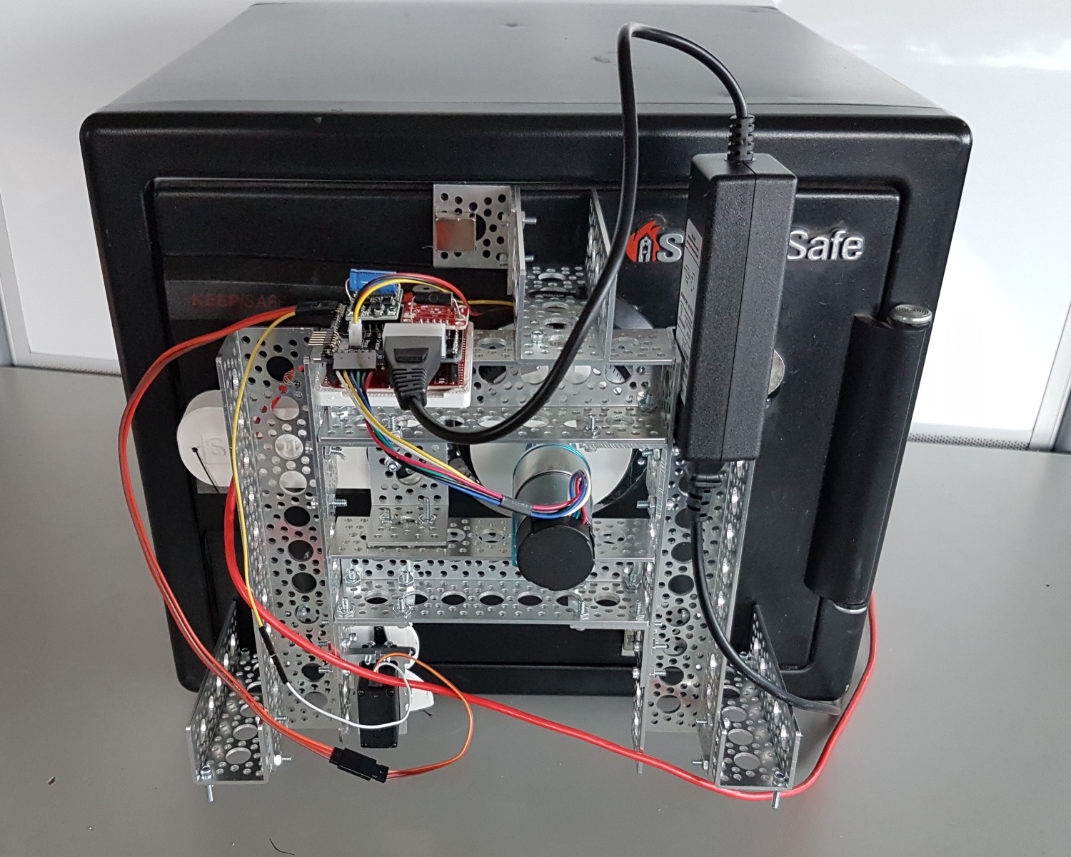
The frame is built with Actobotics parts with magnets hot glued to the three feet. The magnets provide excellent adhesive strength while still being able to attach and detach the robot.
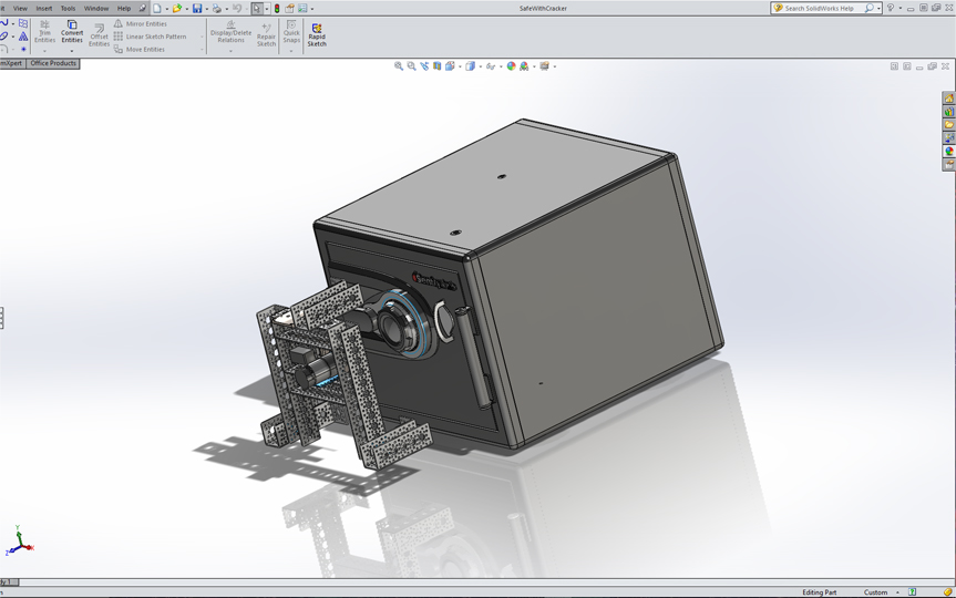
The handle cover, coupler, base plate to hold the electronics, and nautilus gear were printed on our trusty Taz 6 printer.
This frame is specifically designed for our model safe, but the variety of Actobotics parts and the ability to print custom parts means the SparkFun Safe Cracker could be modified to fit any particular model of safe.
How Combination Safes Work
In order to understand some of the shortcuts we took, you’ll need to know how the discs inside a combination lock operate. Here’s a quick primer!
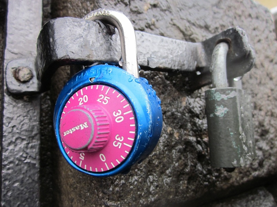
If you’ve ever used a combination padlock you know the basics:
- Spin the dial a few times to reset everything
- Turn the dial in a certain direction until you get to the first combination number. Let’s call that AA.
- Turn the dial in the opposite direction one full turn, then continue until you get to the second number - BB
- Turn the dial in the opposite direction until get you get to the third number - CC
- Pull on the handle to open lock
The most common padlocks have a dial from 0 to 39 with a combination AA/BB/CC. Combination safes work exactly the same but with larger dials, usually 0 to 99. Some safes have additional combination numbers (for example: AA/BB/CC/DD/EE), but the general home-store fire safe is 3 numbers.
But, how do the internals of a combination safe actually work?
Here’s a video to show you the basics:
There are three discs, let’s call them discs A, B and C. Each disc has a notch in it called a gate. When you pull down on the handle, a rod (sometimes called the fence) hits the three dials. If the three gates are lined up correctly, the rod slides into the notches. This allows the handle to travel far enough to disengage the lock on the door, and the safe can be opened.
Turning the dial on the outside of the lock directly controls disc C (sometimes called the drive wheel). Twist it clockwise (CW) or counterclockwise (CCW), and you directly manipulating the C disc. But, how do you move the other two discs?
Each disc has a raised plastic tab. When the discs are next to each other, a disc can move freely for about 350 degrees until its raised tab hits the tab on the next disc and begins moving it.
If you turn disc C a full turn, the tab hits the tab on disc B and begins to turn it. Similarly, disc B has a tab on the opposite side of the disc that will hit disc A’s tab. Turn the dial far enough, and C will pick up and start turning B, which will then pick up and start turning A.
Clear as mud? Check out Woodgears. They have a great breakdown of the pieces and a video showing how the discs are manipulated.
The Problem Domain
The dial on our SafeSentry safe is 100 digits. If there are three discs, our domain is 100 * 100 * 100 or 1 million possible combinations. Testing on a safe at the store, we found it took about ten seconds on average to reset the dial then dial in the three solution numbers. So, worst case, it will take 115.74 days to try every combination. And 10 seconds is pretty fast; humans get tired and less precise over time. Luckily, there are some tricks we can do.
On some high-end, secure safes, if you turn the dial to 81.5 and the combination is 81, it won’t open. With these lower cost home-brand safes the manufacturing tolerances are much larger. On the safe we tried at the store if one of the numbers in the combination is 53 then 52 and 54 will also work.
The first part of this video will show you the tolerances on the combination dial are +/-1 digit.
This quickly reduces the domain to 33 * 33 * 33 = 35,937 combinations. That’s still over 4 days of trying.
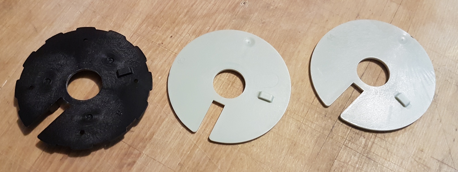
One of the ways to pick a safe is by feel. Manufacturers know this, so, to prevent it, the last disc (we’ll call it disc C) has a series of indents. If you press down on the handle and spin the dial, the thing trying to push down into the notches on the dials, called the fence, will fall into these false indents and lock up the dials. Bummer. But, you quickly figure out that there are 12 indents. And, one of these ‘indents’ must be the correct slot when you dial in the combination.
The problem domain is now 33 * 33 * 12 = 13,068 combinations or 1.51 days. About the speed of paint drying.
The locations of these indents are found easily by hand. 100 / 24 (12 indents, 12 raised bits) = 4.17 dial positions per indent. It’s not super clean, but, if an indent ranges 21 to 25.2, then it’s safe to go to 24 to ‘test’ that indent to see if it’s actually a solution slot.
On our safe we located the indents as follows:
case 0: return (99); //98 to 1 on the wheel
case 1: return (8); //6-9
case 2: return (16); //14-17
case 3: return (24); //23-26
case 4: return (33); //31-34
case 5: return (41); //39-42
case 6: return (50); //48-51
case 7: return (58); //56-59
case 8: return (66); //64-67
case 9: return (74); //73-76
case 10: return (83); //81-84
case 11: return (91); //90-93
Here's what disc C looks like:
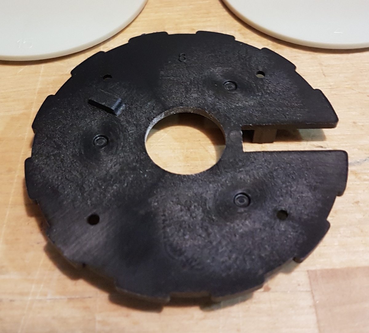
Disc C has the following dimensions:
- Outer diameter: 2.815” (55.5mm)
- Width of solution slot: 0.239”
- Width of 11 indents: 0.249” +/- 0.002”
C = 2πr, so our circumference is 17.69”. Our motor has an 8400 tick encoder. Each encoder tick is therefore approximately 0.0021”. So, we’re looking for a difference of about 5 ticks. Eeek! That's not many.
If we can externally measure the widths of the various slots, we may be able to discern which slot is the skinniest and therefor the solution slot. This would reduce our combination domain to 33 * 33 * 1 = 1,089 and a crack time of 3 hours, worst case.
The function measureDiscC() is designed to take a series of readings and add them together. The motor is a gear head motor and has a tremendous amount of torque, so, if there is any flexing or give in your apparatus, this will show up in the readings as noise. However, if we take many simultaneous readings, any flexion should be replicated to all indent measurements allowing the skinny slot to bubble to the top.
Set screws will not work. A hub that uses a set screw to connect to the D-shaft on a motor will not survive the constant torture of indent measuring. Once we switched to a 6mm clamping hub we had much less noisy readings.
Here’s the output from five measureDiscC() tests on our Craigslist safe with no combination:
Measuring complete
Smallest to largest width [Width]/[Depth]
Indent 8: [1911] / [1130]
Indent 1: [1925] / [1122]
Indent 3: [1953] / [1091]
Indent 0: [1955] / [1099]
Indent 11: [1966] / [1105]
Indent 2: [1992] / [1100]
Indent 9: [1994] / [1126]
Indent 7: [2011] / [1098]
Indent 10: [2036] / [1096]
Indent 4: [2077] / [1109]
Indent 5: [2083] / [1100]
Indent 6: [2114] / [1096]
Indent 8 bubbles to the top on almost all the tests we have run on our safe. We also output the depth measurements (how far does the handle go down), but I am much more suspicious of these readings.
We can’t be sure the smallest indent is the solution ident, or if we’ve even measured the indents correctly so the Safe Cracker firmware allows the user to control which indents are to be tested. Turn them all on, turn on 5, or turn on only one, it’s up to you. We recommend trying to crack your safe with the smallest four indents. If you fail to open the safe then turn these 4 off, turn the other 8 indents to true, and run again.
We are down to 33 * 33 * 4 = 4,356 or a little over 12 hours. Still not great. What other tricks can we do?
Quick Note: When we live streamed the safe cracking, we were conservative and selected four indents to try. The winning indent was indent 8, the skinniest indent. So with two data points, I’d say this vulnerability has potential. You can re-watch the stream if you'd like. The magic moment occurs at 45:20, but start around 44:30 to get the full scope.
Set Testing
If each three combination attempt takes 10 seconds, what can we reduce the time per attempt? We can dial faster of course. But, we can also get sneaky with how we adjust the dials. It takes me 10 seconds because I can’t back up a digit without fouling where the discs are sitting. The robot can be much more precise.
To crack our safe, we set discs A and B, test the indents on disc C, move backwards to adjust disc B, then test the indents again. We call this set testing as opposed to reset testing (where a full reset is done between tests).
The robot attempts combinations this way:
- Reset dials by spinning CCW, past zero, continue until we arrive at zero.
- Continue CCW to 3. This sets disc A to 3.
- Rotate CW to 3. Continue CW to 0. Disc B is now set to 0.
- Rotate CCW to the first allowed indent; ours is 8. Disc C is now set to 8.
- Try the handle. Failed? Continue…
- Rotate CCW to next allowed indent; ours is 24.
- Try the handle. Failed? Continue…
- Rotate CCW to next allowed indent; ours is 66.
- Try the handle. Failed? Continue…
- Rotate CCW to next allowed indent; ours is 74.
- Try the handle. Failed? Continue…
- Rotate CW to 6. Disc B is now set to 6.
- Loop to step 4.
- Rotate CW to 9. Disc B is now set to 9.
- etc...
Here’s a video of set testing, done by hand, to demonstrate what we’re talking about. Jump to 0:41 to see Set Testing in action.
Using this method we can test the AA/BB/xx combinations (set Disc B to 8 then test four indents) in approximately 8 seconds vs. 40 seconds (4 test @ 10s per test). Much faster!
Originally: 33 * 33 * 40s = 12.1 hours
Using Set Testing: 33 * 33 * 8.3s = 2.5 hours worst case!
And, if we’re confident in our single indent the test time comes down to approximately 4 seconds per test (it’s not linear because of the time to move disc B).
Set Testing with one indent: 33 * 33 * 4s = 1.2 hours.
Additional Resources
We hope you enjoyed reading about our safe cracking robot. If you have any questions or discover any other tricks, please let us know!
There are some great videos on how to crack safes, just have a poke around. Eric Schmiedl's talk Safecracking Without a Trace at DEFCON 14 was especially good.